
In order to further improve the product quality of household solar photovoltaic power systems, standardize the market, meet the electricity needs of people in areas without electricity, and better serve the vast number of farmers and herdsmen without electricity, based on our practical experience and research, and taking into account various opinions, the following technical requirements for household solar photovoltaic power systems are proposed for research reference.
1. The meaning and role of technical requirements
A small, independent, and household solar cell power supply device that provides basic household electricity and a small amount of production electricity for farmers and herdsmen in remote and remote areas without electricity is called a household solar photovoltaic power supply system. Its single machine capacity is currently generally below 500W.
In Xizang, Xinjiang, Qinghai, Gansu, Ningxia, Shaanxi, Inner Mongolia and other seven provinces and regions rich in solar energy resources in China, as well as Aba Prefecture and Ganzi Prefecture in Sichuan Province and other places, there are still about 2 million households and more than 10 million farmers and herdsmen who have not yet had access to electricity, living far away from modern civilization, poverty and backwardness. In these areas where the power grid is insufficient, residential areas are scattered, population density is low, electricity load is not large, and solar energy resources are abundant, promoting the application of household solar photovoltaic power supply systems is an important way and approach to solve the basic living electricity and small production electricity needs of non electric farmers and herdsmen. It improves the material and cultural living standards and population quality of farmers and herdsmen, promotes faster local economic and social development, and leads to poverty alleviation and prosperity into a moderately prosperous society, It plays an important role.
2. System classification and composition
According to the different types and methods of power supply, household solar photovoltaic power systems can be divided into three categories: DC type, AC type, and photovoltaic wind complementary type.
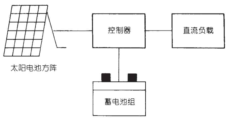
(1) DC type household solar photovoltaic power supply system: mainly composed of a solar cell array, battery pack, and controller, as shown in Figure 1.
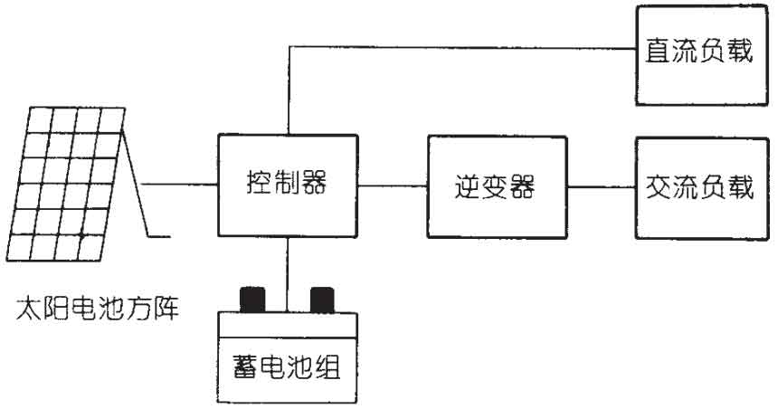
(2) AC type household solar photovoltaic power supply system: mainly composed of a solar cell array, battery pack, controller, and inverter, as shown in Figure 2.
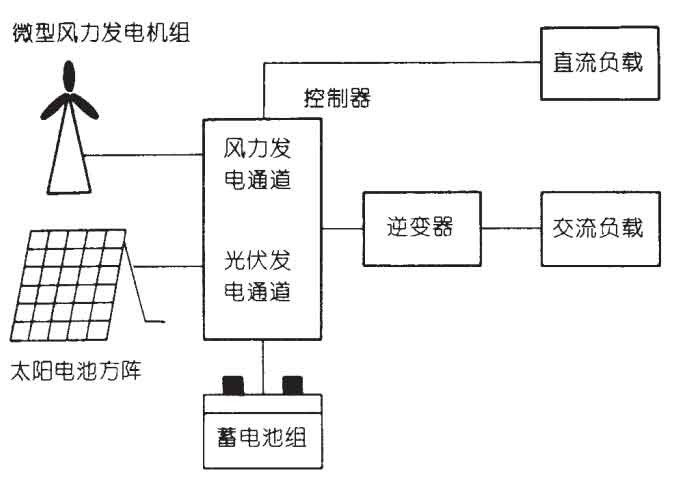
(3) The solar wind complementary household solar photovoltaic power supply system mainly consists of a solar cell array, micro wind turbines, battery packs, controllers, and inverters, as shown in Figure 3.
3. System technical requirements
The overall requirements for household solar photovoltaic power supply systems are: stable power supply, safety and reliability, easy installation, easy use, easy maintenance, durability, long service life, and low price. The specific requirements are as follows:
(1) Usage environment: ① The altitude should not exceed 5000 meters. ② The ambient air temperature around indoor components is -15 ° C to+45 ° C; The ambient air temperature around outdoor components is -40 ° C to+55 ° C. ③ The daily average relative humidity does not exceed 95%, and the monthly average relative humidity does not exceed 90% Except for small portable systems, the maximum wind resistance of solar cell arrays and micro wind turbines should not be less than 120km/h No strong vibration and impact, no strong electromagnetic interference. ⑥ There is no severe dust, explosive hazardous media, harmful gases that corrode metals and damage insulation, conductive particles, or severe mold around.
(2) Technical requirements: ① Solar cell modules shall comply with the provisions of GB/T14007-1992 General Specification for Land Solar Cell Modules and GB/T9535-1998 Design, Identification and Qualification of Ground Crystal Silicon Photovoltaic Modules, as well as GB/T6495.1-1996 Photovoltaic Devices Part #: Measurement of Photovoltaic Current Voltage Characteristics and other national standards. ② Micro wind turbines and their dedicated controllers shall comply with national and industry standards such as GB/T10760.1-1989 Technical Conditions for Small Wind Turbines, GB/T8116-1987 Form and Basic Parameters of Wind Turbines, NJ423-86 Technical Conditions for Low Speed Wind Turbines GB/T13981-1992 General Requirements for Wind Turbine Design, and JB/T6939.1-93 Technical Conditions for Controllers for Small Wind Turbines The maintenance free sealed lead-acid battery pack should comply with the technical requirements and inspection methods of GB1333-1987 fixed acid proof lead-acid batteries, YD/T799-1996 communication valve regulated sealed lead-acid batteries, and JB/T6457.2-92 small valve regulated sealed lead-acid batteries and other national and industry standards The controller should comply with the technical requirements for controllers used in household solar photovoltaic power supply systems. ⑤ Inverters should comply with national and industry standards such as GB7260-1987 Uninterruptible Power Supply Equipment, JB/T7064-93 General Technical Conditions for Semiconductor Inverters, and JB3859.1-1993 Basic Requirements for Semiconductor Converters The system bracket, connecting wires, switches, connectors, etc. should comply with relevant national and industry standards and meet the technical requirements of the system The noise generated by the inverter during operation of components placed indoors should be less than 65dB at a distance of 3m, and the battery pack should be free of lead-acid gas emissions. The warranty period of the entire system should not be less than one year. The design, production, installation, and operation of the entire system should ensure that there are no more than two inspections within one year.
(3) System joint debugging test: The system should undergo joint debugging test before leaving the factory, including: ① Connect the entire system according to the system installation and use manual, and check whether the system can work normally; ② Check whether the installation of solar cell arrays and micro wind turbines (firmness, installation angle, adjustability, and condition of junction boxes, connectors, cables, etc.) meets the requirements; ③ Check if the battery pack (including the connection, box, and leads of the battery for acid mist corrosion and the risk of accidental short circuit) meets the requirements; ④ Check if the working status indicators (meter head, indicator light, etc.) of the controller and inverter are normal; ⑤ Take all the allowed loads of the system and work for 10-20 minutes, observing whether all parts of the system and the loads are working properly.
4. Technical requirements for components
The components that make up a household solar photovoltaic power supply system should meet the following technical requirements.
(1) Solar cell array
① A square array is composed of one or more solar cell components. If the square array is composed of two or more components, it is required that the mismatch loss of component current and voltage should be less than 2%.
② Components should be tested by qualified testing institutions with ISO-25 certification.
③ Requirements for component appearance: a) The frame should be flat and free of corrosion spots; b) The front surface should be clean, without breakage or cracks; c) There should be no scratches, damage or other defects on the back surface; d) Individual solar cells shall not have any breakage or cracks, and shall be arranged neatly; e) The interconnection strips are arranged neatly, without desoldering or breakage; f) There should be no continuous bubbles or delamination in the packaging layer; g) The lead end should be sealed and the polarity markings should be accurate and clear.
④ The requirements for component electrical performance, mechanical performance, and environmental performance should comply with the provisions of various national standards mentioned in the system technical requirements.
⑤ Requirements for square array structure and bracket: a) The design of the square array structure should ensure that the connection between the components and the bracket is firm and reliable, and the replacement of components is convenient. b) The component is installed on a bracket with adjustable tilt angle and should be fixed in multiple places to ensure secure installation. The square array and bracket should be able to withstand a speed of 120km/h without damage. c) The minimum distance between the square array installed on the roof and the roof material should be at least 10cm. The installation bracket must be connected to the main structure of the building and cannot be connected to roof materials. d) The minimum distance between the square array installed on the ground should be 1.2 meters or more. The bottom of the support column must be firmly connected to the support foundation to withstand the weight of the square array and strong winds. e) For portable low-power power supplies, the solar panel should also come with a bracket to allow users to reliably install the solar panel facing south and easily adjust the angle.
⑥ When solar cell modules leave the factory, they must come with: a) or a junction box that can withstand weather effects and ensure wire quality; b) Or connect the weather resistant terminals of the component output cable.
⑦ When solar cell modules leave the factory, they should be marked with: a) manufacturer; b) Component model; c) Production serial number; d) Rated peak power; e) Peak voltage; f) Peak current; g) The standard for testing components.
(2) Micro wind turbine generator set
① The technical performance of micro wind turbines should comply with the provisions of various national and industry standards mentioned in the system technical requirements.
② Towers must be provided randomly. The design of the tower must be able to withstand a wind speed of 120km/h without damage. The tower should be rust proof, preferably electroplated or painted.
③ The foundation of the tower should ensure that it can safely support the tower and withstand the maximum design wind speed.
④ The installation of the unit should comply with the requirements of the ZBF1101-89 low-speed wind turbine installation specification.
⑤ The unit should include a controller. The function of the controller is to protect the system and complete charge and discharge control.
⑥ The installation of the unit must consider the following: a) It should be installed in a location where people and animals do not frequently pass through; b) The propeller blades of the unit should be at least/meter above the ground; c) The unit should be installed in a location where wind power is flowing; d) The unit should be installed as close as possible to the user’s housing to minimize line loss from the unit to the battery; e) The unit and tower should be reliably grounded to prevent lightning strikes.
⑦ In general, the noise level at a distance of 30 meters from the unit should be less than 65dB.
⑧ When the unit leaves the factory, it should clearly indicate the manufacturer, product model, rated voltage, rated power, as well as the production date and serial number.
(3) Battery pack
① A battery pack can be composed of one or more batteries connected in series; The number of parallel batteries shall not exceed 4.
② Due to the use of housing for farmers and herdsmen and the fact that users are farmers and herdsmen, it is recommended to choose valve regulated sealed lead-acid batteries. They are convenient to use, do not require liquid addition, do not discharge acid mist, have a longer lifespan, and are reasonably priced.
③ The technical performance of the battery should comply with the national and industry standards specified in the system technical requirements.
④ The minimum design capacity of the battery pack should ensure a reserve of/day.
⑤ Connect the batteries together using copper plated lead strips or copper strips. The accompanying battery should be equipped with pole posts that are easy to connect with bolts. Anti rust grease should be applied to the electrode end of the battery to protect it from corrosion. The battery should be clearly marked with positive and negative polarity.
⑥ The battery should be placed inside the box. The box should be sealed, ventilated, acid proof, and sturdy.
⑦ At 25 ° C, the maximum self discharge rate of the battery allowed every 3 months is 20% of the discharge capacity at a rate of 10 hours.
⑧ The cycle life of a battery refers to the life of the battery before its residual capacity drops to 80% of its rated capacity. At 25 ° C, the lifespan of shallow cycle batteries must exceed 200 times (average discharge depth 50%), and the lifespan of deep cycle batteries must exceed 600 times (average discharge depth 80%).
⑨ The battery should be labeled with the manufacturer, product model, production serial number, rated voltage, and rated capacity when leaving the factory.
(4) Controller
① The technical performance of the controller should comply with the national and industry standards specified in the system technical requirements.
② The controller can be a standalone device or an integrated machine with an inverter.
③ Requirements for the appearance and structure of the controller: a) The surface coating of the casing should be firm, the paint surface should be uniform, and there should be no peeling, rust, or cracks; b) The shell panel is flat, and the signs, markings, and text meet the requirements. The functional display is clear, correct, and aesthetically pleasing; c) Various switches are easy to operate, flexible and reliable.
④ The controller should have the following protection functions: a) circuit protection to prevent any load short circuit; b) Circuit protection to prevent reverse polarity of loads, solar cell components, or batteries; c) Circuit protection to prevent internal short circuits in controllers, inverters, and other equipment; d) Prevent breakdown protection caused by lightning strikes in thunderstorm prone areas; e) Protection against reverse discharge of batteries through solar cell modules at night.
⑤ For systems with a solar cell array power greater than 20W and systems equipped with micro wind turbines, the controller should have battery fully charged disconnect (HVD) and undervoltage disconnect (LVD) devices and circuit protection.
⑥ The controller should be able to provide users with an indication of the battery’s charging status, including: a) full charge indication, an indication when the battery is fully charged, the charging current of the solar cell array is reduced, or the solar cell array is disconnected; b) Under voltage indication, an indication when the battery voltage is already low and the user needs to save electricity; c) Load disconnection indication, indicating that the load should be disconnected when the battery is under voltage. The indicator is preferably a light-emitting diode (LED), but it can also be an analog or digital meter head.
⑦ The vibration resistance performance of the controller should be able to operate normally even after 30 minutes of vibration in the three axes at 10-55Hz, with an amplitude of 0.35mm.
⑧ The controller should have temperature compensation, and its temperature coefficient should be -3mV/° C~7mV/° C for each battery.
⑨ When the battery voltage drops to the over discharge point (1.8V ± 2.7% per unit), the controller should be able to automatically cut off the load.
⑩ The maximum self power consumption of the controller shall not exceed 1% of its rated charging current.
⑪ The voltage drop through the controller during charging or discharging shall not exceed 5% of the system’s rated voltage.
⑫ When the battery is removed from the circuit, the controller must be able to withstand an impact of 1.25 times higher than the nominal open circuit voltage of the solar cell module within 1 hour.
⑬ The controller must be able to withstand it! Hour higher than the nominal short-circuit current of the solar cell module! $) times the impact. The switching components of the switch type controller must be able to switch this circuit without damaging themselves.
⑭ The controller should clearly indicate the manufacturer, product model, production serial number, rated voltage, rated current, as well as the connection points and polarity of the solar cell components, battery and load when leaving the factory.
(5) Inverter
① The technical performance of the inverter should comply with the national and industry standards specified in the system technical requirements.
② Requirements for appearance and structure: the same as the controller.
③ Main technical parameters: a) Output voltage variation range: not exceeding 10% of the rated value. b) Output frequency 50Hz ± 5%: c) Output voltage waveform distortion ≤ ± 5% (sine wave). d) Efficiency: When the output power is ≥ 75% of the rated power, the efficiency should be ≥ 85%. e) Noise: ≤ 65dB at a distance of 3 meters; f) Load capacity: When the input voltage and output power are at their rated values and the ambient temperature is 25 ° C, the continuous reliable working time should not be less than 4 hours; When the input voltage is at the rated value and the output power is 125% of the rated value, the safe working time should not be less than 1 minute; When the input voltage is at the rated value and the output power is 150% of the rated value, the safe working time should not be less than 2 seconds. g) Static current: After disconnecting the load, the self consumption current value of the inverter should not exceed 3% of the rated input current.
④ It should have protection functions such as undervoltage, overcurrent, short circuit, polarity reversal, and lightning protection.
⑤ The input and output terminals of the inverter should be designed to be inaccessible to the user and installed in a place that children cannot touch.
⑥ When the product leaves the factory, it should indicate the manufacturer, product model, production serial number, input voltage, output voltage, rated power, as well as the connection and polarity between the battery and the load.