
1. Design scope and principles
1.1 Design scope
The design scope of the solar photovoltaic power station system includes system scheme design simulation, electrical primary system design, and electrical secondary system design for the solar photovoltaic plant area. The design scope of the photovoltaic photovoltaic area includes the laying of solar photovoltaic modules, combiner boxes, inverter and boost integrated machine rooms, cable tray layout, cable routing, etc. in the designated area. Specifically, this includes the selection of components and DC equipment, the selection of box inverters, the design of overmatching schemes for solar photovoltaic inverters, the layout design of inverter units, the selection of solar photovoltaic array layout methods, and the estimation of 25 year power generation. Electrical system design mainly includes the selection of cable models, the design of collector line schemes, etc.
1.2 Design Principles
At present, the design technology, equipment, and simulation of solar photovoltaic power stations in China have become relatively mature and commercialized. The design plan should adhere to the principles of reasonable and efficient selection of main equipment, advanced design technology, reasonable project investment plan, unified design standards, and intensive and efficient operation of the power station, while ensuring safety and reliability in advance.
2. Equipment selection
2.1 Selection of solar photovoltaic modules
With the iteration of technology, the power of individual batteries, component power density, conversion efficiency, etc. are gradually increasing.
Due to the current market specifications of monocrystalline silicon modules ranging from 280Wp to 300Wp, and considering factors such as price and technological maturity, this project takes the monocrystalline silicon 290Wp battery module as an example, and its main technical parameters are shown in the table below:
| Peak power (Wp) | 290 |
| Short circuit current (Isc) | 9.47 |
| Open circuit voltage (Voc) | 39.3 |
| Peak voltage (Vmp) | 32.5 |
| Peak current (Imp) | 8.95 |
| Open circuit voltage (Voc) temperature coefficient | -0.30%/K |
| Short circuit current (Isc) temperature coefficient | 0.05%/K |
| Peak power (Pmax) temperature coefficient | -0.39%/K |
| Working temperature | -40 ℃~85 ℃ |
| Size (mm) | 1650×992×35 |
| Weight (kg) | 18.2 |
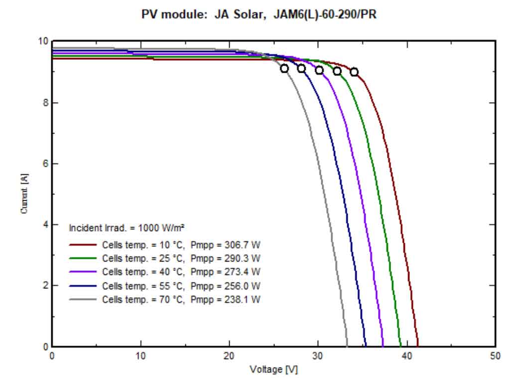
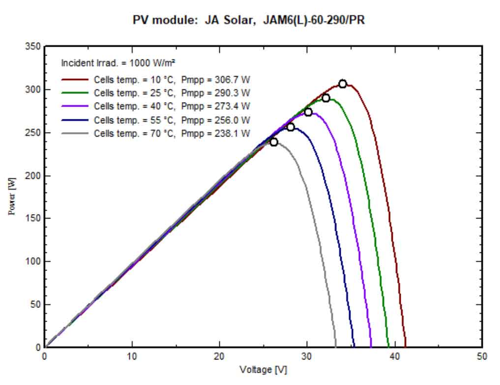
In PVsyst simulation software, taking the 290Wp monocrystalline silicon module with 60 solar cells in JA as an example:
When the irradiance is set to 1000W/m2, the I-V and P-V curves of solar photovoltaic modules under different temperature conditions are shown in the figure:
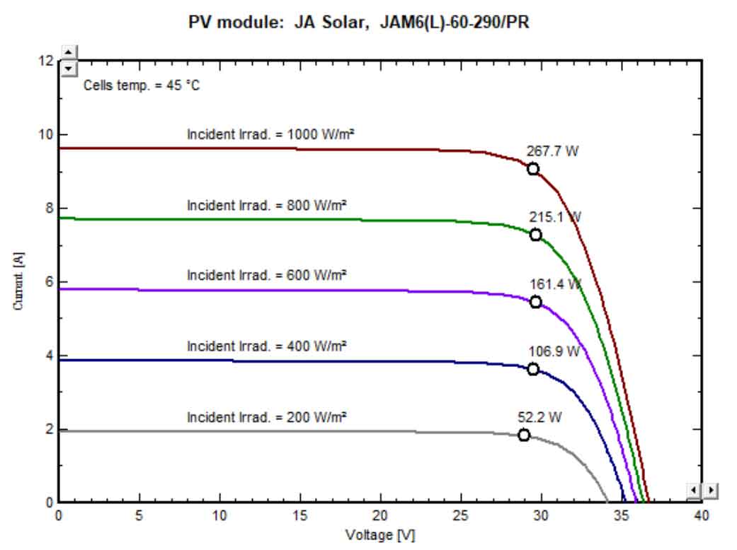
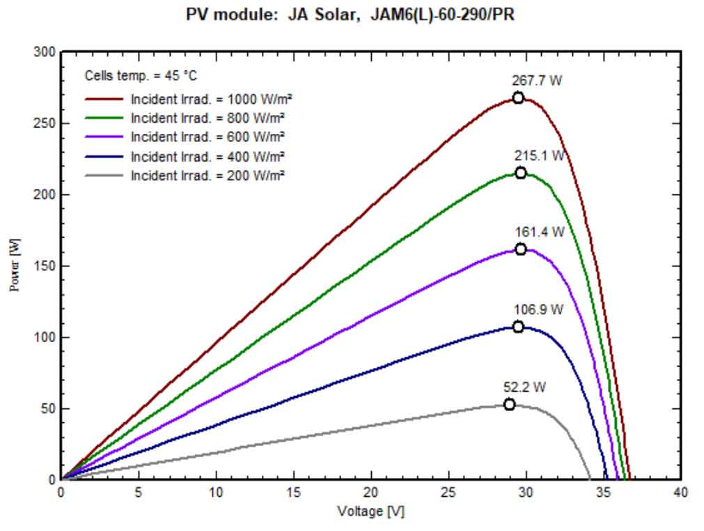
When the temperature is set to 45 ℃, the I-V and P-V curves of solar photovoltaic modules under different irradiance are shown in the figure:
2.2 Selection of inverter boost integrated machine
2.2.1 Model selection of solar photovoltaic inverters
Based on relevant technical specifications, the selection of solar photovoltaic inverters in this project mainly considers the following technical indicators:
| Frequency range | Operational requirements |
| Below 48Hz | Depending on the requirements of the power grid |
| 48Hz~49.5Hz | It is required to run for at least 10 minutes each time below 49.5Hz |
| 49.5Hz~50.2Hz | Continuous operation |
| 50.2Hz~50.5Hz | When the frequency is higher than 50.2Hz each time, the photovoltaic power station should have the ability to continue for 2 minutes, and have the ability to stop supplying power to the grid line within 0.2 seconds. The actual operating time is determined by the grid dispatching agency: photovoltaic power stations that are in a shutdown state are not allowed to be connected to the grid at this time. |
| Above 50.5Hz | Stop supplying power to the grid within 0.2 seconds and do not allow photovoltaic power stations that are in a shutdown state to be connected to the grid. |
(1) High conversion efficiency
(2) Wide voltage range (DC input)
Require that the DC input voltage range of solar photovoltaic inverters is wide enough to increase the power generation when the operating voltage of the battery modules is low.
(3) MPPT tracking
(4) The harmonic content of the AC output of solar photovoltaic inverters should be as low as possible, while the power factor should be as high as possible
(5) Capable of withstanding low voltage
(6) System frequency abnormal response
(7) Reliability and recoverability
(8) Protection function
(9) Monitoring and data collection
2.2.2 Model selection of inverter boost integrated machine
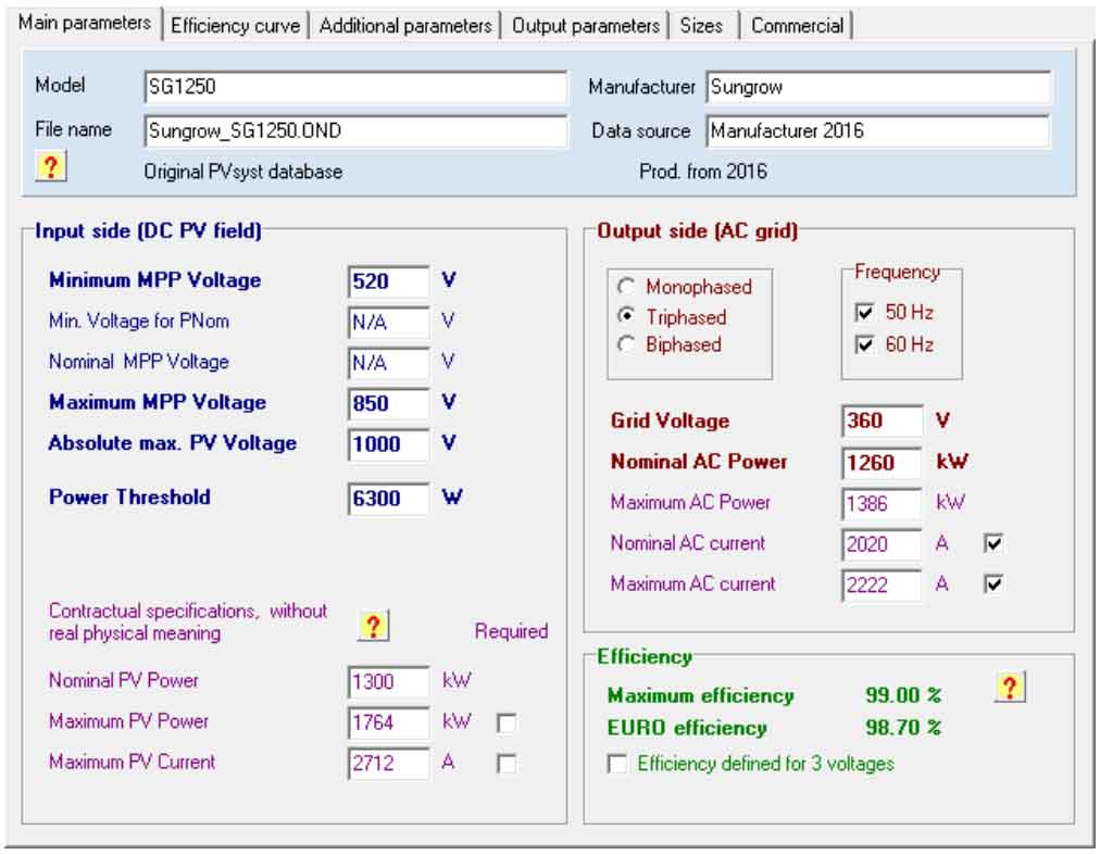
In order to save land and reduce installation and maintenance costs, a 1250kVA inverter and step-up integrated computer room with two 630kW solar photovoltaic inverters and one 1250kVA transformer is selected. The specific parameters are as follows:
| DC output | Recommended maximum photovoltaic array power (kWp) | 708kW |
| DC output | Maximum DC input power (kW) | 708kW |
| DC output | Maximum square array open circuit voltage (V) | 1000 |
| DC output | Maximum input current of square array (A) | 1500 |
| DC output | DC input voltage range (V) | 0-1000 |
| DC output | MPP tracking range (V) | 520-850 |
| DC output | MPP comprehensive tracking efficiency guarantee value (%) | >98% |
| AC output | Rated AC output power (kW) | 630 |
| AC output | Maximum AC output power (kW) | 693 |
| AC output | Normal operating voltage range (V) | 324-396 |
| AC output | Rated grid voltage (V) | 360 |
| AC output | Permissible frequency range (Hz) | 47~51.5 |
| AC output | European efficiency (%) tested according to technical specifications | 98.7% |
| AC output | Comprehensive efficiency guarantee value of complete equipment (%) | 98.5% |
| AC output | Night self consumption (W) | <50 |
| Project | Parameter values |
| Name | Dry type transformer |
| Product model | SCB10-1250/38.5 |
| Operating environment temperature | -40 ℃~50 ℃ |
| Rated voltage ratio | 38.5 kV/0.36kV |
| Maximum working voltage (kV) | 40.5/0.4/0.4 |
| Rated capacity | 1250KVA |
| Tapping range | ± 2 × 2.5% |
| Rated frequency | 50Hz |
| Connection group | Dy11 |
| Impedance voltage | 6% |
| No load current | ≤ 0.75% |
| No load loss | ≤ 2.83kW |
| Load loss (at 120 ℃) | ≤ 12.7kW |
| Cooling method | AN/AF |
| Noise level | ≤ 55dB |
| DC component | The low-voltage winding can withstand a DC component of 1% rated current |
| Short circuit withstand capacity (maximum value) | ≥ 40.5KA |
| Temperature sensor | PT100 |
2.3 DC combiner box
The DC lightning protection combiner box should have the following characteristics:
1) At the same time, it can connect 16 sets of strings, with a maximum current of 15A per set;
2) The fuse withstand voltage value shall not be less than DC1000V;
3) The lightning protection combiner box is equipped with a measurement and control system, which can collect corresponding signals, such as the current, voltage, and power calculation of 16 series parallel groups; And it has arc control alarm and real-time monitoring function for ground insulation.
The selected DC combiner box for this project should be able to operate normally within the range of -25 ℃ to+60 ℃, with a maximum working voltage of 1000V, a rated current of 200A for the circuit breaker, a normal working voltage range of 300V to 1000V, and an insulation strength of 1 minute at AC3500V.
A total of 8 1250kVA inverter boost integrated machines are installed in the station with a capacity of 10.9736MW.
The integrated centralized inverter system with inverter boost adopts a dry-type transformer as the boost transformer, with a double winding type and a connection group type of Dy11, with a voltage level of 38.5 ± 2 × 2.5%/0.36kV, each solar photovoltaic inverter is designed with 8 DC inputs, and each 1.25MW inverter boost container has a total of 16 DC inputs.