
A large domestic power equipment manufacturing enterprise has multiple product divisions under its jurisdiction. With the steady promotion of carbon neutrality, energy conservation and emission reduction, and new energy policies in recent years, its photovoltaic division has consistently ranked among the top in terms of revenue among various departments; Especially in early 2022, due to the company obtaining German TUV technology certification and ISO9001 certification, the solar inverter series products further opened up the European market. In the uncertain situation of the Russia Ukraine conflict, the prices of fossil fuels such as oil, coal, and natural gas, which are highly dependent on Europe, have risen sharply and are facing the possibility of shortages or even supply disruptions. However, in the short term, the consumption level of various energy sources in Europe cannot decrease. Therefore, after May 2022, the order volume of European shipping channels experienced an explosive growth.
To meet the requirements of export orders, the company has increased production capacity and temporarily transferred technical workers from other business units to support the photovoltaic business unit; On the other hand, adopting a three shift work mode further stimulates the potential of the production line. After taking the above measures, the orders in the past three months have basically achieved the expected goals, but some problems have also been exposed. Firstly, shipping still faces enormous pressure. After entering mid to late August, the demand from European customers further increased; A considerable proportion of customers not only offer discounted prices beyond expectations during the business negotiation stage, but also double the demand for subsequent orders. At the same time, delivery time is urgent in order to cope with the energy crisis in autumn and winter. This requires the company to further optimize its production process, connect key nodes to release production capacity. Secondly, unlike previous export customers, European customers have higher requirements for their products. The first party generally hopes that the company will adopt a process management throughout the entire product lifecycle, which can trace and query the data of solar inverters from parts procurement, assembly production, packaging testing, logistics transportation, installation and operation, and other stages. Finally, the management realized that the past few months have been a rare strategic opportunity period, and the company will take this as an opportunity to further integrate various internal subsystems of the enterprise, such as OA/ERP/MES/SCADA, while meeting the shipment requirements of solar inverter orders; At the same time, optimize and upgrade administrative operations, process control, etc., laying the foundation for the next stage of enterprise development.
In order to achieve the above objectives, the company organized business backbone and third-party organizations to conduct research and draw the following conclusion: Firstly, in the early stages of parts procurement, complete machine production, etc., due to the relatively mature application of the company’s existing ERP/MES system, no links that can significantly improve production efficiency were found. Secondly, in the aging testing stage before the solar inverter leaves the factory, except for the aging testing program that has been written into the solar inverter control logic, this part belongs to automated control. In other aspects such as batch control, historical data recording, and process control, the business unit currently adopts manual spot checks and paper records, and has not yet formed an automated process mechanism. In this situation, on the one hand, efficiency is low, switching between multiple batches of aging tests wastes a lot of time, and human recording errors are high; On the other hand, electronic data records of all equipment in the entire batch have not been formed. Thirdly, the existing SCADA system of the Photovoltaic Business Unit, namely the Photovoltaic Operation and Maintenance Intelligent Management Platform of XX Company (hereinafter referred to as the “Photovoltaic Platform”), has relatively complete functions, with reserved interfaces for secondary development during the platform development stage. The aging testing and control logic for a single solar inverter is basically ready. However, due to outsourced development, the OA/ERP/MES system lacks scalability and is difficult to integrate with each other in the short term. After considering the development cost and implementation difficulty, the company urgently needs to develop a solar inverter aging system (hereinafter referred to as the “aging system”) to achieve automated processing of the solar inverter aging testing process, and integrate it with the original SCADA system to electronically record the data during the aging stage throughout the entire cycle.
1. System development requirements
The overall principle of system development is to develop an automated control system that can achieve batch aging testing, integrate with existing SCADA systems, and record test data with minimal workload using existing platforms in a short period of time.
The specific requirements are as follows:
(1) The development and debugging cycle should be as short as possible, and it is required to be completed within one week;
(2) The interface is beautiful, and the test data should be presented in a graphical form as much as possible;
(3) Try to utilize the existing software and hardware conditions of the business unit to reduce development costs;
(4) The control process of solar inverters can be achieved using existing photovoltaic platforms without the need for repeated development in new systems.
(5) Considering the relatively insufficient computer skills of production line workers, the operation of aging systems must be simple and convenient for training and application. One operator can complete the overall aging testing process.
(6) The aging system has a strong anti misoperation mechanism. After the aging test starts, the operator can only view the historical data recorded in the current experiment and cannot terminate the experiment without authorization.
(7) Automatically control the process of aging testing for a certain batch. When the device’s online rate reaches over 95%, start aging testing; If the offline rate of the equipment exceeds 50%, terminate this batch of experiments. After the start of a certain batch of testing, the operator does not need to perform any other operations.
(8) Record the voltage, current, and alarm information of the solar inverters during the aging test process of this batch of solar inverters throughout the entire cycle, and store them in the local database. After the batch is completed, the test data report can be exported, confirmed and signed by the technical leader, and archived. At the same time, photovoltaic platform development can access sub modules of the aging system database and record test data into the entire lifecycle data of product equipment.
2. System architecture and hardware design
The design of an aging system is divided into multiple parts, including process design, software design, database and table structure design. This chapter provides a detailed description of the system architecture and hardware design. Due to the requirement of system development to apply the existing hardware environment as much as possible without increasing development costs, the aging system plan will continue to use the existing aging test bench, communication network, and workstation computer within the business unit, only involving software and process development. The schematic diagram of the existing solar inverter aging test bench in the photovoltaic business unit is shown in Figure 1. This part of the device is uniformly installed in the pre-sales product testing area of the business unit, and the power supply adopts independent dual circuit 380V power supply to ensure power supply stability. The testing site covers an area of about 300 square meters, with a square layout and isolation barriers and warning signs set up outside the site. Each test bench has 5 layers, with a single capacity of 40 solar inverters per set, totaling 10 rows of benches. On a single operation workstation, a two-phase/three-phase power interface is reserved; At the same time, there is an RS 232 communication line installed that supports ModBus communication. The power line interface is installed in the card slot on the left side of the workstation, and the communication line interface is installed in the card slot at the bottom of the workstation; In the cable laying of the test stand, an electromagnetic shielding device is designed between the power line and the communication line to avoid interference between strong and weak electrical signals. The solar inverter is integrated with an IoT communication module, and its IoT antenna is generally installed above the chassis during the testing phase. Wireless signal amplifiers are installed in the four corners and center of the testing area to enhance signal strength.
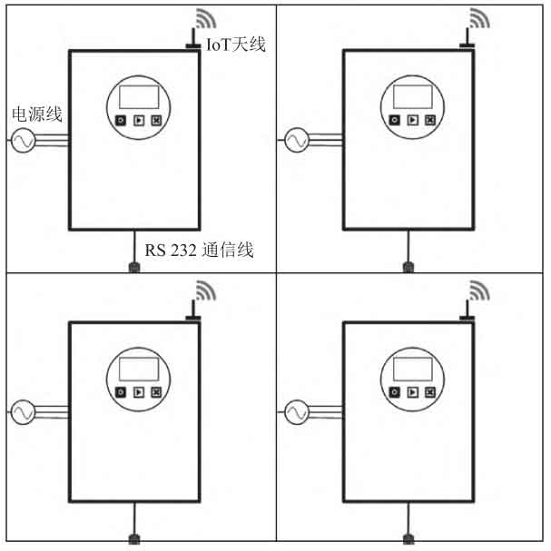
Figure 2 is a schematic diagram of the overall system architecture.
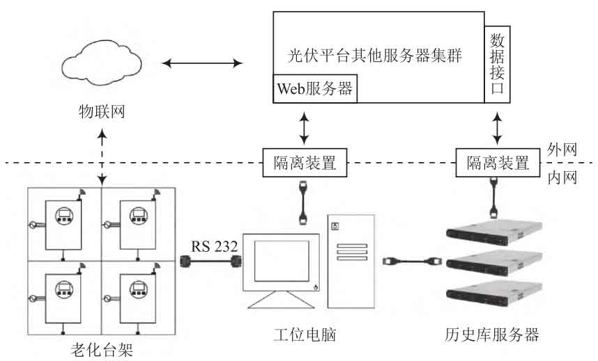
Firstly, provide a brief explanation of the operating environment in which the overall system architecture is located. Due to considerations of data security and factory power supply reliability, the photovoltaic platform was not installed inside the factory area where the business unit is located. The photovoltaic platform system is relatively complex, consisting of a cluster of multiple servers such as web servers, communication front-end servers, data processing servers, alarm servers, database servers, etc., deployed on Alibaba Cloud. The daily maintenance of the server is provided by Alibaba Cloud, and the technical personnel of the business unit only focus on the operation of the platform. The external network where this server is located can be accessed through data isolation devices to access the internal network of the factory area where the business unit is located.
Secondly, the solar inverter is equipped with an IoT communication module, which can communicate with the photovoltaic platform through the IoT module and data services provided by the three major telecommunications operators. The communication protocol and strategy have been deployed separately in solar inverters and photovoltaic platforms, without the need for redevelopment. After the start of a certain batch of aging tests, each solar inverter installed on the aging test bench communicates with the aging system deployed on the workstation computer through RS 232 cable.
Once again, the aging system is deployed on workstation computers and communicates with the historical database servers in the factory area through the company’s intranet. External customers can access a batch of aging test data stored in the historical database through the newly developed data interface of the photovoltaic platform.
Finally, in the aging test, the task of controlling each step of the aging test is mainly completed through communication between a single solar inverter and the photovoltaic platform. The main task of the aging system deployed on the workstation computer is to passively receive test data returned by various solar inverters through the photovoltaic platform and store it in the database. At the same time, overall control should be exercised over the testing batches. On the one hand, this can utilize the complete communication and control process of the existing solar inverters on the photovoltaic platform, reducing the workload of new system development; On the other hand, it can enable R&D personnel to focus on the overall control process and production automation requirements of the new system.
3. System software design
The software design is the focus of this system development, which is divided into four sub modules: process design for aging a single solar inverter, design of photovoltaic platform terminal modules, design of workstation computer end aging system, and database design. The following are detailed explanations.
3.1 Design of aging process for a single solar inverter
The aging process of a single solar inverter involves information exchange among the aging system, photovoltaic platform, and solar inverter. The specific process is shown in Figure 3.
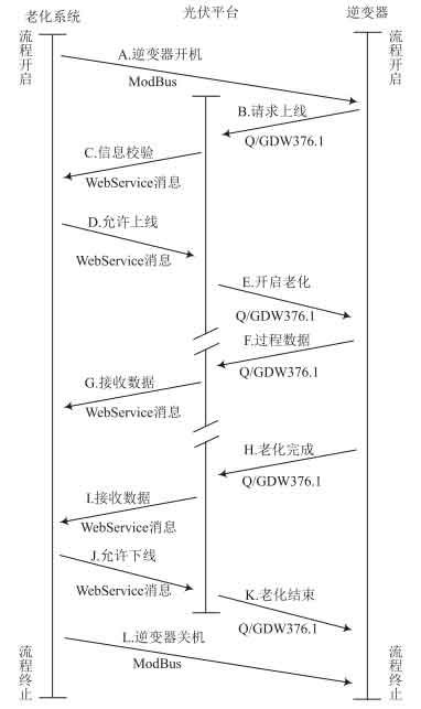
As shown in Figure 3, completing the aging process of a single solar inverter requires 17 steps. The three vertical thick lines in the figure represent the control flow of each stage of aging testing, and the arrows between them represent the data flow and control flow; The text above the arrow represents the serial number and name of the testing step, while the text below the arrow represents the communication protocol applied to the data flow. For example, the text above the first arrow reads “A. Inverter on”; The text below is “ModBus”, with an arrow pointing from the aging system to the solar inverter, indicating that operation step A is to complete the task of turning on the solar inverter. Communication data is sent from the aging system to the solar inverter using the ModBus protocol.
The aging system is mainly responsible for the on/off operation of the solar inverter on the testing bench, verifying the information of the solar inverter, and recording the data during the testing process. The on/off command of the solar inverter adopts the ModBus protocol and is issued through the RS 232 communication line laid in the card slot of the aging test bench. Direct communication between the aging system and the solar inverter. This command changes the output status of any channel in the switch quantity of the solar inverter equipment. It includes sub station address (solar inverter address), function code, switch value address, feature data, and CRC verification code. Among them, function code 05H represents that the data issued belongs to remote control data.
The specific remote control address for controlling the power on/off is 0000H, and the feature data FF00H makes the remote control switch output state ON, that is, the remote control output relay contact is closed, and the solar inverter is turned on; The characteristic data 0000H sets the remote control switch output status to OFF, that is, the remote control output relay contact opens, and the solar inverter shuts down. The startup message is listed in Table 1. The data is all hexadecimal, and the sorting method for multi byte data items is low byte first, that is, small end mode.
| Address code | Function code | Remote control address | Feature data | CRC verification code |
| 01H | 05H | 0000H | FF00H | 8C3AH |
In the information verification step, the aging system mainly checks the information of each device in a certain batch of aging tests, such as verifying the ID number of the solar inverter and the production date of the solar inverter. After the verification is completed, the aging system will issue a command to allow the solar inverter to go online, and the communication message will be transmitted to the photovoltaic platform through the company’s internal network. The communication protocol adopts the WebService message format, which is detailed in Section 4.2. Then, the photovoltaic platform sends commands to the solar inverter through the Internet of Things through the Q/GDW376.8 protocol, and the solar inverter end equipment automatically enters the aging testing process. During the testing process, the solar inverter uses the Q/GDW376.8 protocol to transmit information such as voltage, current, power factor, and quantity of electricity to the photovoltaic platform every 15 minutes; After receiving the data, the photovoltaic platform transforms the protocol format and transmits it to the aging system in WebService message format. After successfully parsing the data, the aging system stores the test records in the database and displays them on the interface accordingly. During the testing process, when encountering emergency situations such as excessive current, high circuit board temperature, and capacitor breakdown, the photovoltaic platform sends control commands to the solar inverter according to the corresponding processing flow, and copies the alarm information to the aging system. During the aging process, the aging system only passively receives various test information and alarm data of the solar inverter forwarded by the photovoltaic platform, and does not directly participate in the aging control process of a single solar inverter. After all solar inverters in a certain batch have completed the aging test, or the completion rate reaches the set number of units, the aging test of this batch will be completed.
3.2 Module Design for Photovoltaic Platform
The task of the photovoltaic platform is a secondary part of the overall project, mainly responsible for the transmission of information between the solar inverter and the aging system, as well as reading the historical database records of the aging system. In the original photovoltaic platform, the control process of the Q/GDW376.8 protocol for solar inverters has been fully implemented. In the new project, there is no need for repeated development, only the aging testing part’s functions need to be opened up. In the information transmission stage, WebService messages are used to communicate with the aging system. The specific communication protocol for each byte is defined in Tables 2 and 3.
| Message partitioning | Name Code | Description | Data type | Byte count |
| CWEBCOMNT_ MSG: MSG_ CLIENT_ HEAD (message header: 5 parts) | Msg_type | value 1 | Int | 4 |
| CWEBCOMNT_ MSG: MSG_ CLIENT_ HEAD (message header: 5 parts) | Uuid | Message ID | Int | 4 |
| CWEBCOMNT_ MSG: MSG_ CLIENT_ HEAD (message header: 5 parts) | Data_ Len | Bytes | Int | 4 |
| CWEBCOMNT_ MSG: MSG_ CLIENT_ HEAD (message header: 5 parts) | Onlysend_ Flag | Value 0 | Int | 4 |
| CWEBCOMNT_ MSG: MSG_ CLIENT_ HEAD (message header: 5 parts) | Wait_ Count | Timeout/s | Int | 4 |
| CWEBCOMNT_ MSG: MSG_ TASK (Task header: 7 parts) | Opper_type | Value 99 | Int | 4 |
| CWEBCOMNT_ MSG: MSG_ TASK (Task header: 7 parts) | Nextframe | Value 0 | Int | 4 |
| CWEBCOMNT_ MSG: MSG_ TASK (Task header: 7 parts) | Bakresult_ Flag | Value 0 | Char | 1 |
| CWEBCOMNT_ MSG: MSG_ TASK (Task header: 7 parts) | Bakcode_ Flag | Value 0 | Char | 1 |
| CWEBCOMNT_ MSG: MSG_ TASK (Task header: 7 parts) | Bakcodejx_ Flag | Value 0 | Char | 1 |
| CWEBCOMNT_ MSG: MSG_ TASK (Task header: 7 parts) | Subst_ ID | Power Station ID | Int | 4 |
| CWEBCOMNT_ MSG: MSG_ TASK (Task header: 7 parts) | Collector_ ID | collector ID | Int | 4 |
| Data_ Type_ Vect (Task Body: Content Type, 2 Parts) | Data_ Type_ Num value is 1 Int 4 | Value 1 | Int | 4 |
| Data_ Type_ Vect (Task Body: Content Type, 2 Parts) | Data_ Type value is 0x401 Int 4 | Value 0x401 | Int | 4 |
| Data_ Bytenum_ Vect (Task Body: Bytes of Content, 2 parts) | Data_ Bytenum_ Num | Value 1 | Int | 4 |
| Data_ Bytenum_ Vect (Task Body: Bytes of Content, 2 parts) | Data_ Bytenum | Message byte count | Int | 4 |
| Data (Task Body: Content, Part 2) | Data_ Byte | count of len message | Int | 4 |
| Data (Task Body: Content, Part 2) | Data_ FRM | 376 message | Char | Undetermined |
From Tables 2 and 3, it can be seen that WebService messages are defined in the format of message partitioning, with the next level of defined fields separated from each partition; The overall message format adopts the format of embedding WebService messages within Q/GDW376.8 messages. In Table 2, the message header (CWEBCOMNT-MSG:: MSG-CLIENT-HEAD) part of the message partition is msg_ The value of type is always 1, indicating that such messages need to be communicated between the aging system and the solar inverter through a relay platform (i.e. photovoltaic platform); The message ID of uuid has an initial value of 0 after the aging test process begins, and a frame value is sent with an increase of 1; Other fields such as only send_ Flag, operator_ The values of type, nextframe, etc. are fixed and customized for aging testing; Subst in task header partition (CWEBCOMNT-MSG:: MSG-TASK)_ The ID field of the power station is generally set to 0 by default, which refers to the ID of the testing station before leaving the factory; Data in the task body partition (Data)_ Fill in the Q/GDW376.8 message in FRM, but the actual length may vary. The partition and field meanings of each message in Table 3 are similar to those in Table 2.
| Message partitioning | Name Code | Description | Data type | Byte count |
| CWEBCOMNT_ MSG: MSG_ SERVER_ HEAD (message header: 3 parts) | Msg_type | Value 1 | Int | 4 |
| CWEBCOMNT_ MSG: MSG_ SERVER_ HEAD (message header: 3 parts) | Uuid | Message ID | Int | 4 |
| CWEBCOMNT_ MSG: MSG_ SERVER_ HEAD (message header: 3 parts) | Data_ Len | Bytes | Int | 4 |
| CWEBCOMNT_ MSG: MSG_ BODY (Task Body: 5 Parts) | Rx_ Flag | Receiving flag | Char | 1 |
| CWEBCOMNT_ MSG: MSG_ BODY (Task Body: 5 Parts) | Jx_ Flag | 0 | Char | 1 |
| CWEBCOMNT_ MSG: MSG_ BODY (Task Body: 5 Parts) | FRM_ Len | 376 Report Text Section Count | Int | 4 |
| CWEBCOMNT_ MSG: MSG_ BODY (Task Body: 5 Parts) | Data_ Frm | 376 message | Char | frm_ Len bytes |
| CWEBCOMNT_ MSG: MSG_ BODY (Task Body: 5 Parts) | JXFrm_ len | Value 0 | Int | 4 |
3.3 Aging System Design
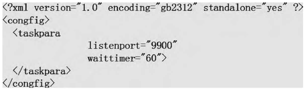
Before the aging test of a certain batch begins, the production line workers need to organize the information of the solar inverters participating in the aging test of this batch as required, and form a CSV electronic file. The document contains information such as the total number of solar inverters, ID number, model, and power of each solar inverter. After the aging test begins, the system first performs an initialization detection process, mainly checking the communication status of the network monitoring port between the system and the photovoltaic platform, the connection status of the historical database, and reading the local workstation computer time, which is stored in the log. The network listening port and historical library connection parameters can be configured through the XML files in Figures 4 and 5. For the convenience of display, make slight adjustments to the original file format in the two figures.
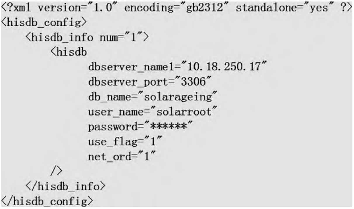
The operating system of the workstation computer is Windows 7 or Windows 10. To avoid the occurrence of Chinese garbled characters, the encoding method is GB2313. The waiting time for listening to the port is set to 60 seconds.
After completing the initialization detection, the CSV files organized by the production line workers will be read into the aging system, and the system will create a new data table for this batch of aging tests in the historical database based on the information in the files. Then, the aging system sends a startup command to each solar inverter on the rack in ModBus protocol format via RS 232 communication line. The startup message format is listed in Table 1. After receiving the power on command, the solar inverter sends a Q/GDW376.8 message requesting to go online to the photovoltaic platform via the Internet of Things; Subsequently, the photovoltaic platform encapsulated it as a WebService message and forwarded it to the aging system. On the aging system end, parse the specific information of the solar inverter in the message and verify it with the information in the historical database. If it is consistent, the solar inverter is allowed to wait for online operation; After the number of solar inverters in the same batch reaches the set value, the aging process officially begins. In the aging process, the system stores the test data and alarm information of each solar inverter in the historical database server. The format of each data table in the historical database will be detailed in Section 3.4. Meanwhile, on the operating interface of the software, data and alarm information are displayed using data graphs and clearly distinguishable tables, as detailed in Chapter 4. After all solar inverters have completed the testing process, this batch of aging tests will be completed.
3.4 Historical Library Design
Considering the tight development time of aging systems, the design positioning of historical libraries should be as simple as possible while meeting application requirements. The overall database design consists of 5 data tables, of which 4 tables are used to record aging test batches and specific data values, and 1 table is an alarm information index table, as listed in Tables 4-8.
Table 4 records the name and information of a batch of experiments for aging testing. Among them, Testid serves as the primary key of the table and is assigned by the aging system in order by default, and cannot be manually modified. Testname is the name of an experiment. When a new experiment is created, the system automatically reads the local time from the industrial computer and names it “Experimental Batch YYYY MM-DD hh mm”. The experimental name can be manually modified as needed. Devnum is the number of solar inverters used in this batch of experiments and requires manual input. The Starttime and Endtime fields are converted using UTC time and automatically programmed in the system; The data format defined as Int is to save storage space.
| Field Name | Data type | Null value | Primary key |
| Testid | Varchar(16) | Not Null | Yes |
| Testname | Varchar (40) | Null | No |
| Devnum | Int | Null | No |
| Starttime | Int | Null | No |
| Endtime | Int | Null | No |
Table 5 records the specific information of solar inverters in a certain batch of aging tests. The Verifyid field records the verification ID number of a single solar inverter. The primary keys of the data table are Testid and Verifyid. By combining the two, it is possible to locate the specific aging test batch in which the solar inverter appeared.
| Field Name | Data type | Null value | Primary key |
| Testid | Varchar(16) | Not Null | Yes |
| Verified | Varchar (32) | Not null | Yes |
| Devname | Varchar (40) | Null | No |
Table 6 records the test data of the solar inverter during the aging test process. Among them, the Dtime field is the data reporting time of the solar inverter, which is generally required to be submitted every 5 minutes; However, due to the different timing of data transmission for each solar inverter, it is refreshed every minute in the aging system data display interface to reduce data latency; This field also uses UTC time. Status represents the current working status of the solar inverter: 0- shutdown, 1- startup, 2- pending online, 3- operation, 4- malfunction, 5- testing. During the aging test process, other values may appear except for state 3. Data1 to Data40 are various data of solar inverters, such as A, B, C three-phase voltage, current, frequency, power factor, etc.
| Field Name | Data type | Null value | Primary key |
| Tested | Varchar (16) | Not null | Yes |
| Verified | Varchar (32) | Not null | Yes |
| Dtime | Int | Not null | Yes |
| Status | Int | Null | No |
| Data1 | Float | Null | No |
| … | … | … | … |
| Data40 | Float | Null | No |
Table 7 stores the alarm information that occurred during previous aging tests. The Level field represents the level of the alarm. This system is designed with three types: 0-normal fault/state, 1-general fault, and 2-serious fault. Normal faults/states only have two values: standby and running; Under normal faults, the solar inverter can operate with faults, but in severe faults, the solar inverter must be shut down. The Descrip field describes the specific information of the alarm, and its string is automatically generated by the system in the format of “Devname”. The “Desc” fault occurred at XX time; The time is automatically converted from Dtime to Beijing time, and “Desc” is obtained by querying the corresponding field in Table 8.
| Field Name | Data type | Null value | Primary key |
| Tested | Varchar (16) | Null | No |
| Verified | Varchar (32) | Null | No |
| Devname | Varchar (40) | Null | No |
| Dtime | Int | Null | No |
| Level | Int | Null | No |
| Descrip | Varchar (128) | Null | No |
Table 8 is an immutable alarm information index table for generating specific device record information. Meanwhile, the Info field provides a detailed description of the fault. The information in Table 8 is inserted through SQL statements during the deployment phase of the aging system, as listed below. There are a total of 126 SQL statements, where inverteralarm is the name of the data table.
| Field Name | Data type | Null value | Primary key |
| Id | Int | Not null | Yes |
| Desc | Varchar (64) | Null | No |
| Level | Int | Null | No |
| Info | Varchar (128) | Null | No |
Insert INTO ‘inverteeralarm’ VALUES (‘0 ‘,’ standby mode ‘,’ 0 ‘,’ solar inverter in standby mode ‘);
Insert INTO ‘inverteeralarm’ VALUES (‘1 ‘,’ running state ‘,’ 0 ‘,’ solar inverter in running state ‘);
Insert INTO inverteralarm VALUES (‘2 ‘,’ fault state ‘,’ 1 ‘,’ solar inverter in fault state ‘);
Insert INTO inverteralarm VALUES (‘3 ‘,’ total fault bit ‘,’ 1 ‘,’ detected fault bit ‘);
Insert INTO ‘inverteralarm’ Values (‘4 ‘,’ no grid ‘,’ 2 ‘,’ grid voltage less than 50 V ‘);
4. Interface design and implementation
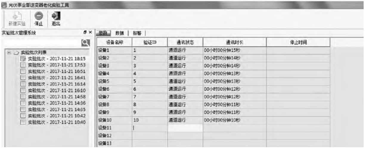
The interface layout of the aging system is shown in Figure 6. List experimental batches on the left side of the interface; Design three buttons in the menu bar: New Experiment, Stop, and Exit; The data on the right is divided into three types of options. Figure 6 shows the parameters section, which lists the device name verification ID and communication related data. The new experiment button is grayed out, as the latest batch experiment shown in the screenshot has already been opened, the button is not operable. The figure shows virtual test data for 2017.
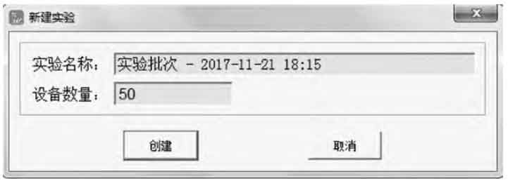
When the production line workers click the button for creating a new experiment, a new experiment batch naming and equipment quantity confirmation interface will pop up as shown in Figure 7.
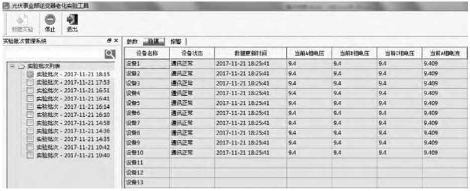
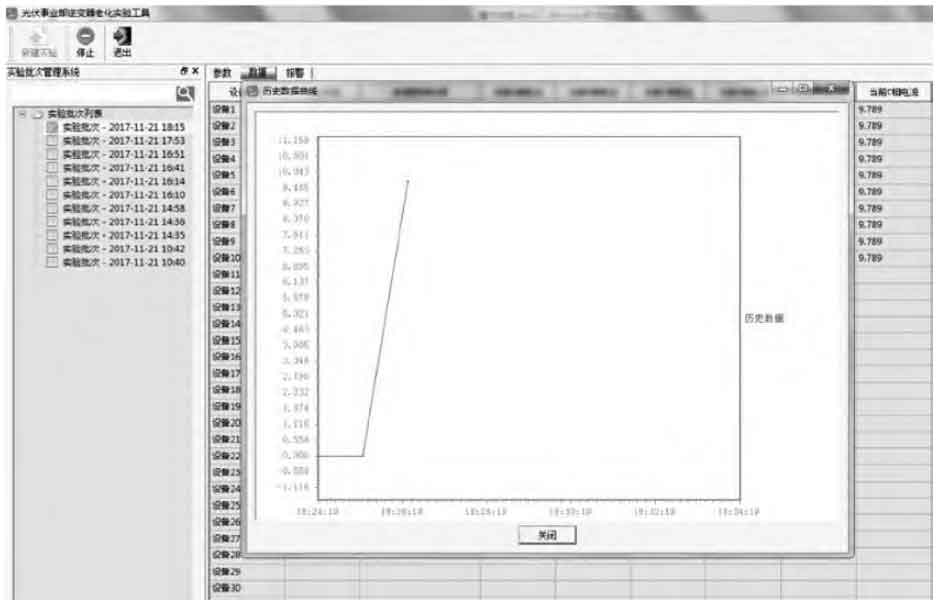
Figures 8 and 9 show the situation of the data interface. Figure 8 shows the numerical display of the data; After double clicking on a numerical cell, the numerical curve interface up to the previous data refresh time can be opened, as shown in Figure 9.
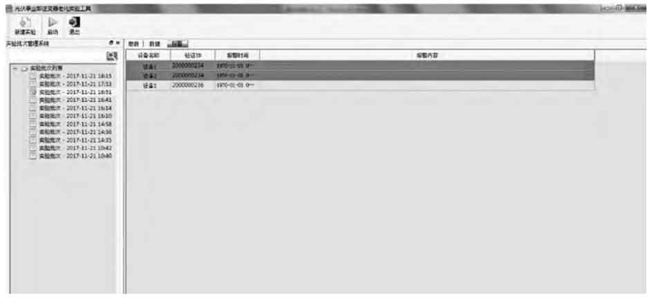
The alarm interface is shown in Figure 10. For severe faults, i.e. alarm data with a Level value of 2 in Tables 7 and 8, the records are highlighted in red; For general faults, they are highlighted in yellow and do not change color for normal faults/states.
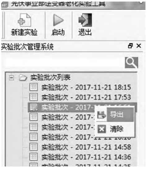
After a certain batch of experiments is completed, the operator can export experimental data from the left experimental batch and submit it to the person in charge for signature and archiving. As shown in Figure 11, the deletion of experimental batches is only not displayed in the interface display section, and the test data will not be deleted from the historical library.
5. Conclusion
This article focuses on the problem of insufficient production capacity of solar inverters in the photovoltaic business unit, and designs a photovoltaic aging testing system for the aging testing stage. This system can be preliminarily integrated with the original photovoltaic platform and automatically control the aging experiment process, reducing the probability of human error and significantly improving production efficiency. After a week of research and development testing, it was successfully delivered to the business unit for application and achieved good results. Next, consider further integrating the OA/ERP/MES between the system and administrative functional departments to improve the company’s level of informatization.