
Photovoltaic power generation is integrated into the grid through full power converters. From the perspective of the grid, its fault characteristics mainly manifest as the fault characteristics of solar inverters, which are significantly different from traditional synchronous machines. The fault characteristics of solar inverters are determined by the fault crossing control strategy they adopt, which has strong controllability. Studying the fault characteristics of solar inverters under different control strategies is of great significance for the safe and stable operation of new power systems dominated by new energy.
There is no equivalent circuit for constant potential and impedance series connection in solar inverters, and the study of their fault characteristics must be combined with detailed topology structure, control circuit, and control objectives. Currently, researchers have conducted extensive research on the fault characteristics of solar inverters. Through the combination of theory and simulation, it was found that the basic composition, attenuation rate, and amplitude characteristics of short-circuit current in solar inverters are significantly different from those of synchronous generators; We simulated and analyzed the short-circuit current characteristics of solar inverters under various conditions such as AC power grid faults and IGBT device faults, and concluded that the short-circuit current should not exceed 1.5 times the rated current; Considering the limiting characteristics of the PI controller, the differences in transient changes of short-circuit current in solar inverters were studied when the controller operates in the linear and nonlinear regions, respectively; Derived a steady-state short-circuit current calculation formula that does not rely on the control structure and parameters of solar inverters; In the calculation of short-circuit current, the influence of bus voltage fluctuation and unloading circuit was taken into account, and the influence of PI controller parameters, voltage drop depth, load level and other factors on the fault characteristics of photovoltaic power supply was analyzed; Studied the method for solving short-circuit current in distribution networks that takes into account distributed power sources; Starting from the decaying DC component and negative sequence component in the short-circuit current output of photovoltaic systems, the generation mechanism of second and third harmonics in the output current of solar inverters was studied; Considering the dynamic response of the phase-locked loop, a more accurate expression for short-circuit current in solar inverters is provided.
However, the above literature did not consider the influence of different negative sequence control strategies in theoretical and simulation analysis. In fact, solar inverters can control both positive and negative sequence currents simultaneously. Three negative sequence control objectives that solar inverters can adopt were studied in detail: suppressing negative sequence currents, suppressing reactive power doubling frequency fluctuations, and suppressing active power doubling frequency fluctuations. In synchronous machine systems, during a fault, there is only a unique negative sequence source at the fault point in the negative sequence network, and the distribution of negative sequence voltage and current is relatively clear. If the solar inverter controls the negative sequence current, the solar inverter itself may also become a negative sequence output source, which will have a significant impact on the fault characteristics of the solar inverter. At present, there is a small amount of literature that considers the influence of negative sequence control strategies in the study of fault characteristics of solar inverters. For example, three different negative sequence control strategies have been mentioned, but only one strategy of suppressing negative sequence current has been selected for research; For different negative sequence control strategies, the influence of equivalent negative sequence sudden variable impedance phase angle characteristics on fault component directional components of inverter power supplies was studied. Although the expression of short-circuit current for inverter power supplies was derived in the article, the output short-circuit current characteristics of solar inverters under different fault types were not studied by combining different negative sequence control strategies.
Regarding the current research on the fault characteristics of solar inverters, the influence of different negative sequence control strategies has not been fully considered. This paper first derives the solution method for the short-circuit current of solar inverters, and then focuses on three different negative sequence control strategies. The variation characteristics of the output short-circuit current and equivalent negative sequence impedance of solar inverters under different negative sequence control strategies under asymmetric fault conditions are studied in detail, and verified through simulation.
1. Derivation of short-circuit current for solar inverters
Solar inverters generally adopt a dual loop control architecture with a power outer loop and a current inner loop, which has strong control ability over the output current.
When the PI controller is designed reasonably, the output current of the solar inverter can quickly follow the command value, and the transient response process of the controller can be ignored.
Assuming that the positive sequence current d and q-axis command values in the forward synchronous rotating coordinate system are i+d * and i+q * during a solar inverter fault, and the negative sequence current d and q-axis command values in the reverse synchronous rotating coordinate system are i-d * and i-q *. The steady-state short-circuit current output by the solar inverter can be expressed as:
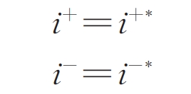
In the formula: i+=i+d+ji+q, where i+d and i+q are the positive sequence current d and q-axis components in the forward synchronous rotating coordinate system; I -=i-d+ji-q, where i-d and i-q are the negative sequence current d and q-axis components in the reverse synchronous rotating coordinate system; I+=i+ d+ji+* q; I *=i * d+ji – * q; J is an imaginary unit.
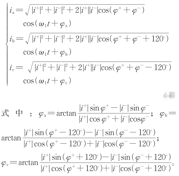
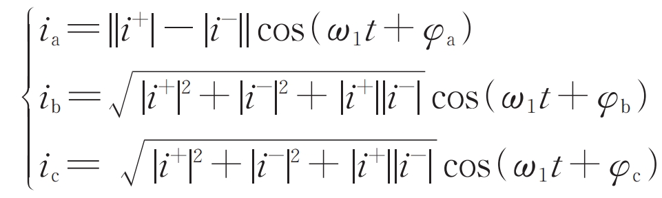
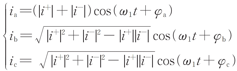
Assuming that at time t=0, the d-axis coincides with the a-axis, perform Park inverse transformation on the formula in the forward and reverse synchronous rotation coordinate system, and then add the two to obtain the steady-state short-circuit current of the solar inverter output phase separation:
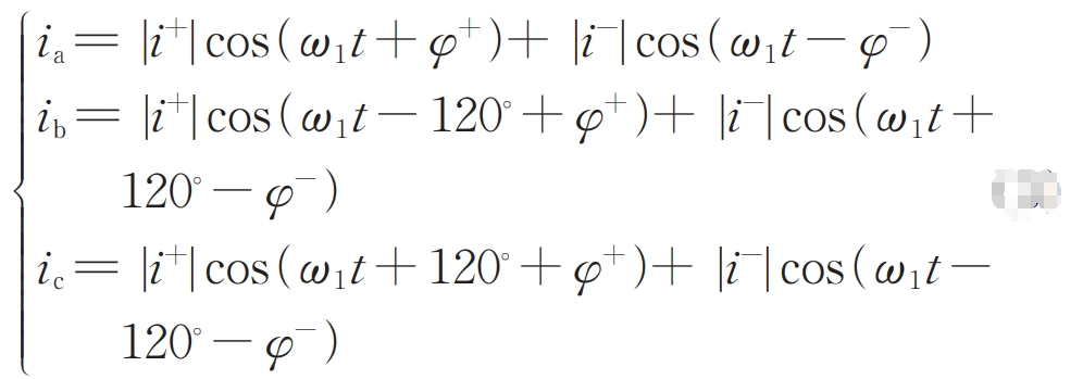
In the formula: φ+ = Arctan (i+q/i+d); φ- = Arctan (i-q/i-d); ω 1 is the synchronous angular velocity.
The formula can be further organized as follows:
2. Fault crossing control strategy for solar inverters
The specific values of the positive and negative sequence current command values of the solar inverter during the fault period are determined by its positive and negative sequence fault crossing control strategy.
2.1 Positive sequence traversal control strategy
When using d-axis voltage oriented control, controlling the positive sequence currents i+d and i+q on the d and q axes respectively can achieve independent decoupling control of the active and reactive power output of the solar inverter.
According to the requirement of low voltage ride through, the solar inverter should transmit reactive power support voltage to the grid during the fault period, and the reactive current command value i+q * is given according to the formula.
In the formula: UT is the unit voltage value of the grid connection point; IN is the rated current per unit value of the solar inverter.
At present, there is no requirement in the regulations for the active current output during the period from fault occurrence to fault removal. The general approach is:
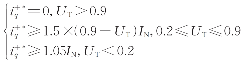
When UT>0.9, priority is given to the output of active current, and under the limiting condition (1.2IN in this article), the remaining margin is used for the output of negative sequence current; When UT ≤ 0.9, reactive current output is prioritized, and after deducting reactive current output and negative sequence current output, if there is additional margin under current limiting conditions, it is used to output active current.
2.2 Negative sequence crossing control strategy
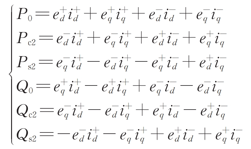
When the system is in an asymmetric operating state, the power fed into the grid by the solar inverter will oscillate, leading to a significant decrease in the quality of output power and affecting the safe operation of the grid. When the voltage and current of the power grid are asymmetric, the output power of the solar inverter can be expressed as:
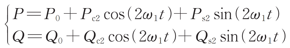
In the formula, e+d and e+q represent the positive sequence d and q axis grid voltage in the forward synchronous rotating coordinate system, respectively; E-d and e-q are the negative sequence d and q-axis grid voltages in a reverse synchronous rotating coordinate system, respectively.
There are three main negative sequence control objectives reported in domestic and foreign literature:
1) Goal I: Suppress negative sequence current in the power grid, i.e. i -=0.
2) Goal II: Suppress the second harmonic oscillation of reactive power in solar inverters, i.e. Qc2=0 and Qs2=0.
3) Goal III: Suppress the active power double frequency oscillation of solar inverters, i.e. Pc2=0, Ps2=0.
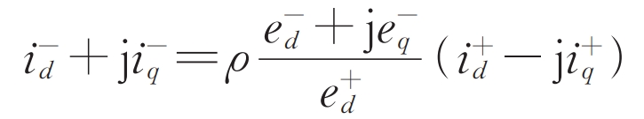
When using d-axis voltage orientation, e+q is equal to 0. According to the formula, the unified expression of the negative sequence current command value for each control objective can be obtained as follows:
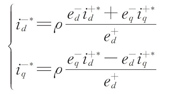
In the formula: ρ= 0, 1, and -1 correspond to control objectives I, II, and III.
3. Analysis of fault characteristics of solar inverters
3.1 Analysis of Asymmetric Fault Current Characteristics
According to the formula, the relationship between the steady-state output positive and negative sequence short-circuit currents of the solar inverter can be further obtained:
From this, it can be inferred that:
According to the formula, the phase relationship between the positive and negative sequence short-circuit currents output by the solar inverter depends on the negative sequence control strategy adopted and the negative sequence fault voltage.
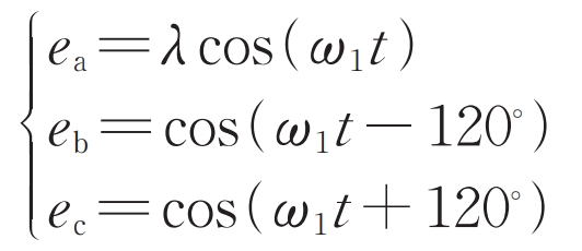
1) Single phase ground fault
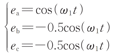
Taking the grounding fault of phase A as an example, assuming that the voltage of phase A in the power grid drops to λ (0 ≤ λ< 1) Then it is approximately assumed that the voltage of the other two phases remains unchanged, i.e.:
Performing the Park inverse transformation on the formula in a reverse synchronous rotating coordinate system yields:
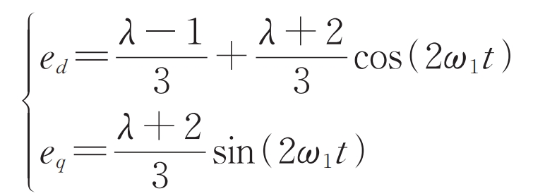
In the formula, ed and eq consist of two parts, with the DC component corresponding to the negative sequence voltage and the double synchronous speed component corresponding to the positive sequence voltage, i.e. e-d=( λ- 1) /3, e-q=0.
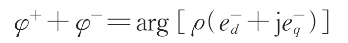
When using negative sequence control target I, i -=0, according to the formula, the equal amplitude of short-circuit current in each phase is | i+|.
When using negative sequence control objective II, according to the formula, it can be obtained that φ+ +φ- = By substituting 180 ° into the formula, we can obtain:
In the formula: φ A φ B φ The size of c is related to the relative sizes of | i+| and | i – |.
It can be seen that at this time, the amplitude of the short-circuit current in phase A of the faulty phase is the smallest, while the amplitude of the short-circuit current in phases B and C is equal, which is significantly different from the fault characteristics of traditional synchronous machines.
When using negative sequence control objective III, according to the formula, it can be obtained that φ+ +φ- = By substituting 0 ° into the formula, we can obtain:
At this time, the amplitude of the short-circuit current in phase A of the faulty phase is the highest, while the amplitude of the short-circuit current in phases B and C is equal.
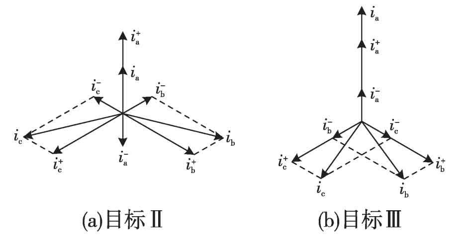
Combined with the formula, it can be seen that when using target II, the phase difference between the positive sequence current and negative sequence current of phase A is 180 °, that is, the two are reversed; When using target III, the phase difference between the positive and negative sequence currents of phase A is 0 °, and they are in the same direction. Based on this feature, the phasor diagram shown in Figure 1 can be drawn, where i φ ( φ= a. B, c) is the phasor of each phase current, i+ φ For the positive sequence component of each phase current, i- φ The negative sequence component of each phase current. From Figure 1, it can be seen that using the phasor diagram, it is very convenient to draw a conclusion that is completely consistent with the formula.
Other single-phase grounding faults can refer to the above analysis, and the conclusion is consistent with the A phase grounding fault.
2) Two phase short circuit fault
Taking the BC phase short circuit as an example, according to the boundary conditions and composite sequence network diagram, it can be seen that the voltage of phase A at the fault point is still the pre fault voltage, while the voltage of phases B and C becomes -0.5 times the pre fault voltage of phase A. There are:
According to the analysis of phase A grounding fault, the following conclusion can be drawn: when using target II, φ+ +φ- = 0 °, the expression for short-circuit current is consistent with the target III for phase A grounding fault; When target III is adopted, φ+ +φ- = 180 °, consistent with the expression used for target II for ground fault in phase A.
Two phase short circuit grounding fault can refer to the analysis of two phase short circuit faults, and similar conclusions can also be drawn.
In summary, when an asymmetric fault occurs, under the premise of voltage drop mentioned above, the amplitude characteristics of the short-circuit current output of the solar inverter under different negative sequence control strategies are shown in Table 1.
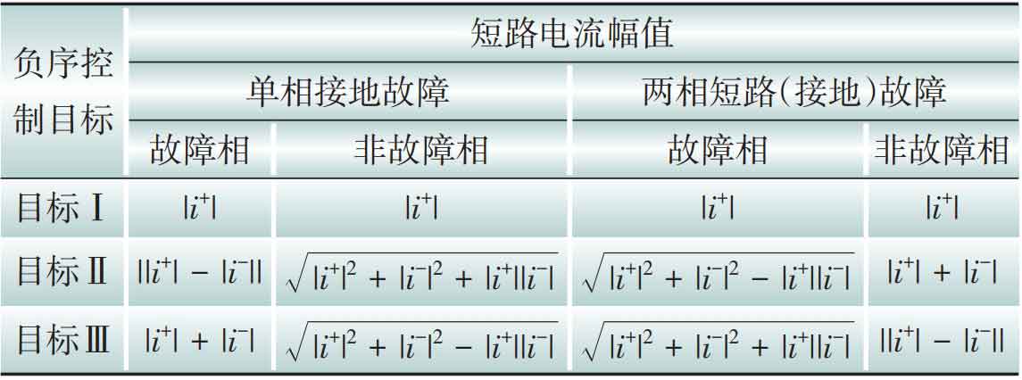
From Table 1, it can be seen that when i – ≠ 0, the steady-state short-circuit current characteristics of the solar inverter output can be summarized as follows:
(1) When using negative sequence control target I, the amplitude of the short-circuit current in each phase is equal, and there is no negative sequence component in the short-circuit current.
(2) When using negative sequence control objective II, the amplitude of the fault phase short-circuit current is smaller than that of the non fault phase short-circuit current.
(3) When using negative sequence control target III, the amplitude of the fault phase short-circuit current is greater than that of the non fault phase short-circuit current.
(4) The single-phase ground fault characteristics when using negative sequence control target II are similar to the other two-phase short circuit (ground) faults when using negative sequence control target III.
(5) The single-phase ground fault characteristics when using negative sequence control target III are similar to the other two-phase short circuit (ground) faults when using negative sequence control target II.
It should be noted that in some literature, the reactive current command value when UT<0.2 is set as the limit amplitude, and all current margins will be used to output reactive current. Under different negative sequence control objectives, there will be no negative sequence current output. The three-phase short-circuit current of the solar inverter is always symmetrical, and the amplitude of each phase current is equal.
The difference in the output short-circuit current characteristics of solar inverters is caused by different control strategies, which fully demonstrates the strong controlled characteristics of the output short-circuit current of solar inverters. Under different fault control strategies, the same type of fault presents different fault characteristics, while different types of faults may present the same fault characteristics, posing a serious challenge to traditional fault phase selection and protection setting.
3.2 Analysis of equivalent negative sequence impedance characteristics
The equivalent impedance characteristics are very important for the analysis of relay protection principles. Since there is no negative sequence component before a fault, the equivalent negative sequence impedance can be calculated from the negative sequence voltage and current after the fault:
By substituting the formula, we can obtain:
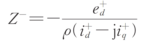
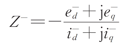
According to the formula, the equivalent negative sequence impedance amplitude of the solar inverter is equal to the ratio of the amplitude of the positive sequence voltage to the positive sequence current, and the impedance phase is related to the positive sequence active and reactive currents, as well as the negative sequence control strategy used. Assuming that the solar inverter outputs reactive power according to the requirement of low voltage ride through after a fault, that is, i+q ≥ 0. As inverter type new energy generally sends active power, that is, i+d ≥ 0. On this premise, if the solar inverter adopts negative sequence control target I, its equivalent negative sequence impedance is infinite. If negative sequence control target II is used, its equivalent negative sequence impedance angle is between -90 ° and -180 °. If negative sequence control target III is used, its equivalent negative sequence impedance angle is between 0 ° and 90 °.
It can be seen that under different negative sequence control strategies, there is a significant difference in the equivalent negative sequence impedance characteristics of solar inverters, which may have an impact on the traditional phase selection and directional components that use negative sequence components.
4. Simulation verification
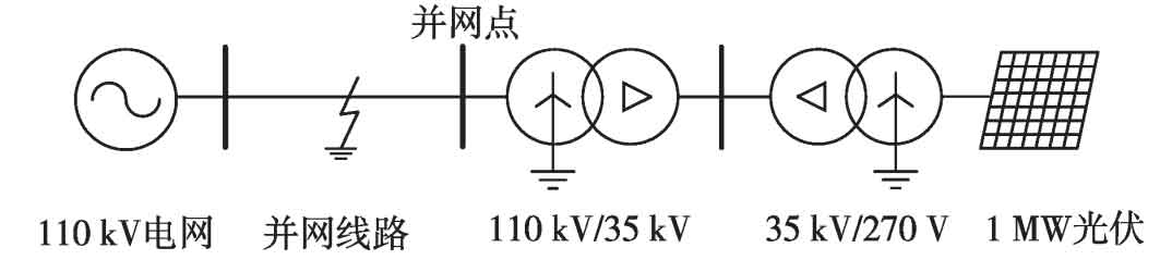
Using the electromagnetic transient simulation software PSCAD/EMTDC, a grid connected simulation model of a solar inverter is constructed as shown in Figure 2. After two stages of boosting, a 1 MW solar inverter is connected to the 110 kV infinite grid through the grid connected line. The relevant model parameters are as follows: the leakage reactance of a 35 kV transformer is 0.065 pu, the leakage reactance of a 110 kV transformer is 0.105 pu, and the rated capacity of the transformer is both 1.2 MW; The positive sequence impedance of the grid connected line is (0.19+j2.68) Ω, and the zero sequence impedance is (1.78+j8.6) Ω.
4.1 Single phase ground fault
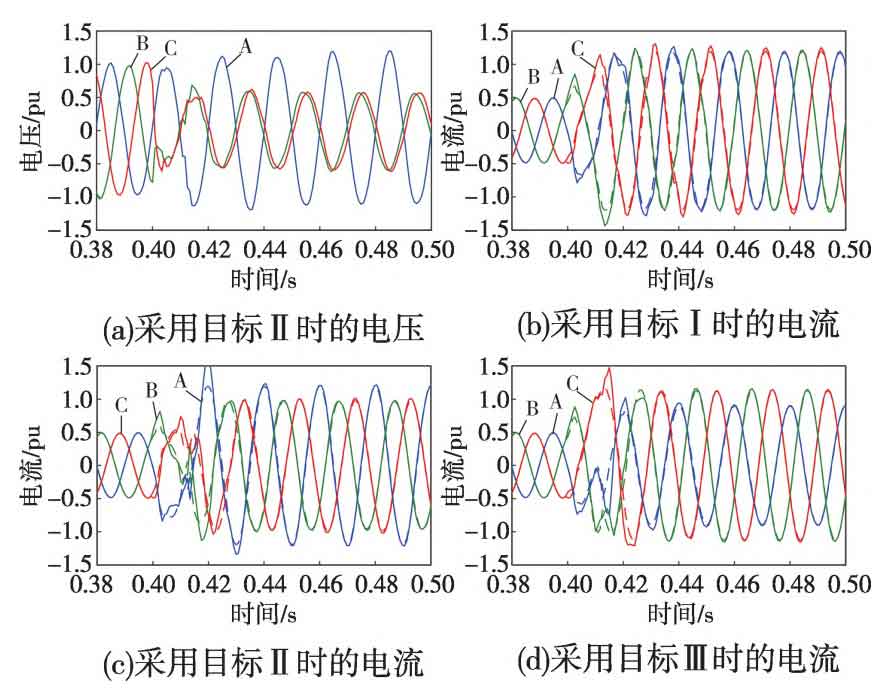
Before the fault, the solar inverter output 0.5 times the rated power. At 0.4 seconds, an A-phase metallic grounding fault occurred at the midpoint of the grid connected line. The output voltage of the solar inverter under control objective I and the output current waveform of the solar inverter under different control objectives are shown in Figure 3. The solid line in the current waveform represents the simulation result, and the dashed line represents the result calculated using formula theory. Due to the fact that the actual current is in a dynamic process following the command value about one cycle after the fault, there is a slight deviation between the theoretical value and the simulation value. After entering the steady state, the two basically overlap, verifying the correctness of the expression for steady-state short-circuit current.
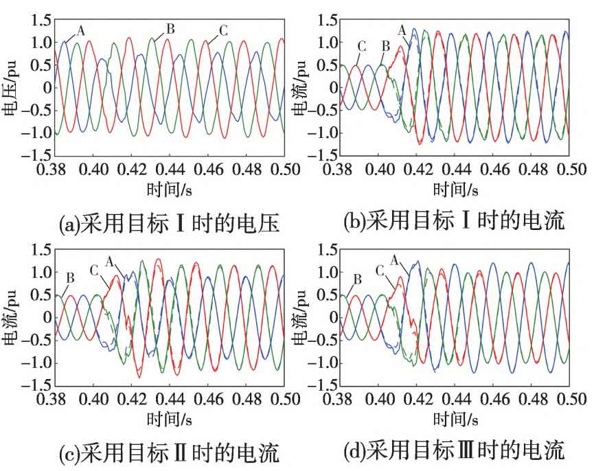
From Figure 3, it can be seen that the output voltage of the solar inverter in phase A drops, while the voltages of phases B and C remain basically unchanged. When the negative sequence control strategy adopts control target I, the output current of the solar inverter is three-phase symmetrical and basically has no negative sequence current. When target II is used, the fault phase A current is the smallest, and when target III is used, the fault phase A current is the largest, which is completely consistent with the analysis results in Table 1, This intuitively reflects the impact of different negative sequence control strategies on the output fault characteristics of solar inverters. The equivalent negative sequence impedance amplitude and phase angle characteristics of solar inverters under different control objectives are shown in Figure 4. The solid line represents the negative sequence impedance amplitude and phase angle obtained by extracting the negative sequence component from the three-phase voltage and current at the outlet of the solar inverter and calculating the phasor using the full wave Fourier algorithm. The dashed line represents the result calculated using formula theory. Due to the transient process of voltage and current around one cycle after a fault, and the full wave Fourier algorithm having a transient data window of one cycle, there is a certain deviation between the theoretical values and simulation values in the first two cycles after a fault. However, after transitioning to steady state, the two basically match.
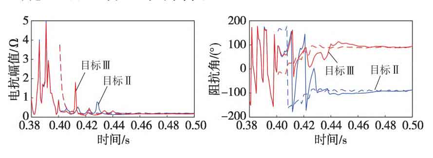
As shown in Figure 4, when using control objectives II and III, the steady-state amplitude of the equivalent negative sequence impedance is approximately equal, but there is a significant difference in phase angle. Due to the significant voltage drop at the grid connection point, the active current command value of the solar inverter is close to 0, and the reactive current command value is 1.05 pu. It can be seen that the steady-state phase angle is around -90 ° when using objective II, and around 90 ° when using objective III, which is consistent with the theoretical analysis results.
4.2 Two phase short circuit fault
Before the fault, the solar inverter output 0.5 times the rated power. At 0.4 seconds, a BC two-phase short circuit fault occurred at the midpoint of the grid connected line. The output voltage of the solar inverter under control target II and the output current waveform of the solar inverter under different control targets are shown in Figure 5.
From Figure 5, it can be seen that the voltage of phase A at the outlet of the solar inverter slightly increases, while the voltage of phases B and C is approximately half of the voltage of phase A, with opposite phases. When using control objective II, the non fault phase A has the maximum current, while when using objective III, the fault phases B and C have the maximum current. From the current waveform, it can be seen that in steady-state, when target II is used for the B and C two-phase short circuit, it is very close to when target III is used for the A phase ground fault, while when target III is used for the B and C two-phase short circuit, it is very close to when target II is used for the A phase ground fault. Under different types of faults, adopting different negative sequence control strategies may result in similar fault characteristics.
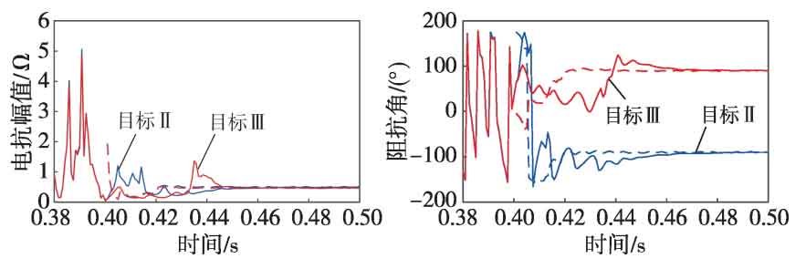
The equivalent negative sequence impedance amplitude and phase angle characteristics of solar inverters under different control objectives are shown in Figure 6, and the results are similar to the ground fault of phase A, which will not be repeated.
5. Conclusion
By combining theory and simulation, it is pointed out that there are significant differences in the short-circuit current characteristics of solar inverters under different negative sequence control strategies under the same fault condition; Under different fault conditions, if different negative sequence control strategies are adopted, the output short-circuit current characteristics of solar inverters are similar. In addition, under different negative sequence control strategies, there are also significant differences in the amplitude and impedance angle of the equivalent negative sequence impedance of solar inverters. Therefore, in the process of studying the fault characteristics and protection principles of new energy integration into the power grid, it is necessary to fully consider the impact of negative sequence control strategies.