
The application of modern portable electronic devices is becoming increasingly widespread and mature. Modern portable devices, represented by embedded systems, are applied in various fields, promoting the development and innovation of electronic technology, and bringing great convenience and epoch-making impact to human production and life. Portable systems have different meanings in different fields. In the field of electronic technology, portable devices refer to electronic devices that are easy to operate and carry. The indicators of portable electronic devices include volume, power consumption, heat dissipation, continuous working time, standby time, service life, etc. The volume of portable electronic devices is determined by the manufacturing process of microelectronic devices, system power consumption, heat dissipation performance, and other parameters; The use of devices in the circuit directly affects system power consumption. The large size of the device results in high system power consumption, high power requirements, and small device size results in poor system heat dissipation performance. Power consumption and volume are mutually constrained and balanced, and the optimal device is selected reasonably. The power supply includes: power supply battery, power supply mode, power management technology, system energy-saving technology, etc. This article elaborates on modern portable system power supply technology, management technology, energy-saving technology, as well as the principles and methods of DC-DC converters from practical applications. A simple circuit, low power consumption, and high efficiency DC power supply is designed. After testing, the power supply has high output accuracy, high stability, strong adaptability, and strong load capacity, Widely used in modern portable electronic devices.
1. Principles of power supply for modern portable devices
1.1 Principle of Portable Power Supply
Coarse electricity refers to the poor quality of primary AC electricity, which needs to be converted into fine electricity or DC electricity in most practical applications. According to the output, portable power supplies can be divided into four categories: rectifier AC-DC, inverter DC-AC, variable frequency AC-AC, and DC converter DC-DC. Portable power supplies can be divided into LDO linear DC stabilized power supplies and switching power supplies based on different composition principles. Switching power supplies can be divided into isolated switching power supplies and non isolated switching power supplies. LDO linear DC stabilized power supply, with small ripple, high power consumption, and a low efficiency of 30% to 40%, is not suitable for efficient portable electronic devices; The isolation switch adopts a transformer to regulate the output voltage, which is safe and efficient, with an efficiency of up to 80%. However, it is technically difficult, costly, and has a large volume, and is used for larger electronic devices; Modern portable electronic devices generally use lithium batteries for power supply, and the portable power circuit uses DC-DC DC conversion to convert the battery output DC voltage into various DC voltages required by the system. It has high conversion efficiency and low static current, and is a commonly used portable power conversion circuit in modern portable electronic devices.
DC-DC conversion is the process of converting a fixed DC voltage into the DC voltage output required by the system. Through DC chopping, the input voltage is chopped into a pulse square wave, which is then boosted or lowered by energy storage components. After rectification and filtering, a high efficiency, high precision, and high stability secondary DC voltage is output. The control methods of DC-DC conversion circuits can be divided into hard switching technology and soft switching technology. Hard switching includes PWM pulse width modulation and PFM pulse frequency modulation. PWM modulation does not change the switching cycle, but changes the switching duty cycle to control the output voltage amplitude; The PFM modulation method maintains a constant duty cycle, and the frequency of the modulation signal varies with the amplitude of the input signal; A soft switching resonant converter utilizes an LC series parallel resonant network to achieve zero voltage conduction ZVS and zero current turn off ZCS, achieving zero power consumption for switching on and off, and reducing converter switching losses. The main circuit forms of DC-DC converters include Buck buck chopper, Boost boost chopper, Buck Boost buck or boost chopper, etc. Different circuit forms are selected according to the requirements of portable devices.
1.2 Energy saving technology for portable power supplies
Modern portable device power supply technology is mature, and the continuous working time, standby time, and service life of portable devices have become the focus of competition among major manufacturers. The most direct way to increase the continuous working and standby time of portable devices is to increase the capacity of lithium batteries, improve the conversion efficiency of portable power supplies, and reduce system power consumption. According to Moore’s Law, the integration degree of internal components in integrated circuits doubles every 18 months, leading to an increase in CPU data throughput, processing speed, and system power consumption. The development speed of lithium batteries is far from keeping up with the development speed of integrated circuits, and the relatively lagging development of batteries has become a bottleneck restricting the development of portable electronic devices. The main methods to improve the power conversion efficiency of portable devices include improving the efficiency of rectifier devices and reducing the static current inside the portable power supply. Traditional PWM controlled DC-DC converter, with average system power consumption Pav=CO × V2DD × f. CO load equivalent capacitance, VDD power supply voltage, f switching frequency, it can be seen that the power consumption of the DC-DC converter is directly proportional to the switching frequency and the square of the portable power supply voltage. Reducing the switching frequency of the converter can effectively reduce the number of switching actions and power consumption, at the cost of reducing the CPU data processing speed. As the volume of passive components in the portable power supply device increases, the static power consumption increases,; The current processor’s main frequency is constantly increasing, and the data processing speed is accelerating. To reduce system power consumption, the only way is to lower the power supply voltage.
The main losses of DC-DC DC converters are rectifier diodes and freewheeling diodes. Even with the use of fast recovery diodes (FRD), ultra fast recovery diodes (SRD), and Schottky diodes (SBD), significant voltage drops are generated on the diodes, reducing power efficiency. Traditional diode rectifier circuits are no longer sufficient for modern portable electronic devices. Currently, the power supply of portable devices mainly adopts synchronous rectification technology, using on state resistors with extremely low power MOSFETs, Replacing rectifier diodes and reducing their conduction voltage drop, synchronous rectification technology requires the gate voltage to be synchronized with the rectified voltage phase, effectively reducing rectification losses and improving the efficiency of portable power supplies.
Portable device power intelligent management technology refers to the intelligent management of device voltage and current in chronological order, real-time control of module output voltage based on user usage, effective allocation of power supply, reduction of static current of power modules, reduction of idle device energy consumption, and maximum reduction of losses to improve system efficiency. Hardware management refers to the selection of COMS devices with low static current in hardware circuits to reduce static power consumption; Software management refers to the use of portable power managers to dynamically manage power and reduce idle device power consumption. Modern smartphones have very comprehensive functions, and different functions require different power supplies, such as answering and making calls, sending text messages, listening to music, wireless internet, and watching movies. Adopting intelligent power management technology can effectively reduce system power consumption and improve the power efficiency of portable devices.
The portable device power supply adopts the system rectifier module sleep technology to improve power efficiency. The rectifier module sleep technology dynamically controls each set of rectifier modules in the power supply system in real time based on the output current size, timely closes unnecessary rectifier modules, reduces system load loss and no-load loss while ensuring output. The rectifier module sleep technology uses software to set sleep time and sleep order according to actual needs. The sleep technology of rectifier modules requires portable power systems to have at least two or more sets of rectifier modules, which improves the efficiency of portable power sources while also increasing hardware costs and increasing the actual cost of portable devices.
2. Power supply applications for modern portable devices
2.1 Principle of MC34063
MC34063 has a wide input voltage range, low static current, high output driving current, and high oscillation frequency. It is a typical bipolar modern portable device DC-DC portable power controller, with an input voltage of 3.0-40V, an output voltage of 1.25-40 V, a maximum output current of 1.5 A, a maximum voltage of 40 V between the collector and emitter of the switching tube, and a switching oscillation frequency of 100 Hz to 100 kHz. It can achieve power supply boosting and lowering Reverse equal transformation, with an efficiency of over 80%. The internal module principle and pin functions of MC34063 are shown in Figure 1.
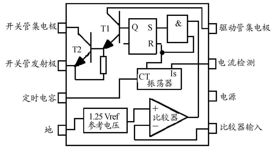
MC34063 contains a 1.25 V bandgap reference portable power supply, voltage comparator, oscillator, logic controller, and switching transistor. Compare the input voltage of the 5th pin of the MC34063DC-DC converter with the 1.25V bandgap reference voltage. The comparison results show that the input logic controller and oscillator output oscillation square wave are in phase, and the logic level is input into the RS trigger to control the switching tubes T1 and T2; The oscillator contains a constant current source inside, and the third pin is externally connected to a timing capacitor to adjust the oscillation frequency. The external capacitor is charged, and the oscillator and comparator output a high level simultaneously. The RS trigger is set to 1 switch to conduct. The current IS detection terminal detects the real-time RSC voltage of the 7-pin resistor. If the voltage at the current detection terminal exceeds 300mV, the external capacitor CT of the oscillator is quickly charged and discharged to control the duty cycle of the switching tube and stabilize the output voltage. The electrical parameters of MC34063 application are shown in Table 1, and the electrical parameters are adjusted appropriately for different application conditions.
| Parameter Name | Symbols | Typical value |
| Power current/mA | IVCC | 2.7 |
| Capacitor charging current/uA | ICHG | 31 |
| Capacitor discharge current/uA | IDISCHG | 190 |
| Current limit detection voltage/mV | VSENSE | 300 |
| Switching tube T1 saturation tube pressure drop/V | VC (SW) | 0.95 |
| Switching tube T2 saturation tube pressure drop/V | VE (SW) | 0.45 |
| Comparator threshold voltage/V | VTH | 1.24 |
| Comparator bias current/nA | IBIAS | 50 |
2.2 Voltage reduction circuit and parameter calculation
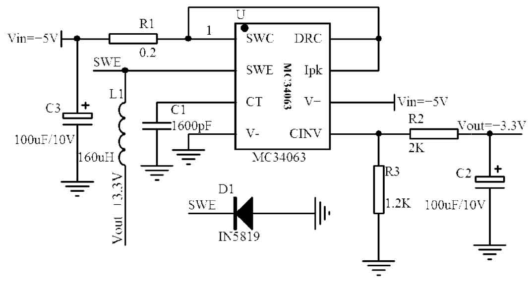
Design a step-down DC power supply using MC34063DC-DC converter with input voltage+5V output voltage+3.3V ripple less than 10 mV. Output current IO (max)=500 mA. The principle is shown in Figure 2. The step-down circuit current flows through the detection resistor R1, switch tubes T1 and T2, inductor L1, capacitor C1, freewheeling diode D1, and load RL. Monitor the output voltage Vout=1.25 by comparing the external resistance R2 and R3 on pin 5 of the reverse input terminal through a comparator × (1+R2/R3). The DC-DC converter is in TON state, and the RS trigger inputs a high level at the S end. The switching tubes T1 and T2 conduct, and the current flows through the collector of the switching tubes to the emitter. The second pin is externally connected to the energy storage element inductor L1 to charge the capacitor C1. The inductor L1 reaches the maximum peak current IPK and stops magnetization. The freewheeling diode D1 is cut off in reverse; The DC-DC converter is in the TOFF state, and the RS trigger inputs a low level at the S end. The switching tubes T1 and T2 are cut off, and the second pin is connected to an external energy storage element inductor L1 and capacitor C1 to discharge and provide current to the load. The freewheeling diode D1 is turned on. Due to the inability of the inductor current to suddenly change, the output current direction remains unchanged. As long as the switching frequency and the charging and discharging speed of the energy storage element are fast enough, the load can obtain continuous DC voltage and achieve voltage reduction.
3. Performance parameter testing
The testing instruments for the MC34063DC-DC converter circuit include a UNI-T four and a half digit digital multimeter UT56 and a Tektronix 100 MHz digital storage oscilloscope TDS2014C. The load resistance uses a 10 Ω rated power 5 W cement resistor. After actual testing, the performance parameters of the portable power supply are shown in Table 2. The portable device power converter composed of MC34063DC DC has stable and reliable output, small ripple, excellent linear and load adjustment rates, high efficiency, strong adaptability, and can fully meet the practical requirements of portable devices.
| est parameters/V | UOUT=+3.3 | UOUT=+5 |
| Output voltage/V | 3.36 | 5.05 |
| Maximum output current/mA | 499 | 501 |
| Ripple/mV | 6 | 8 |
| Linear adjustment rate/% | 0.09 | 0.07 |
| Load adjustment rate/% | 0.06 | 0.08 |
| Efficiency/% | 87 | 88 |
4. Conclusion
The MC34063DC-DC converter power control circuit has a small size, low cost, high efficiency, low static current, low standby power consumption, and effectively improves the standby time, working time, and service life of modern portable device power batteries. It is an ideal power converter for modern portable devices and can be widely used in practical life.