
The battery certification of portable power systems is showing an increasing trend, partly due to the increasing number of incidents of personal injury caused by improper charging of counterfeit rechargeable batteries. In addition, ensuring the safety of rechargeable battery power supply systems circulating in the market has become an increasingly important factor for many government agencies. Therefore, electronic manufacturers must ensure that their products do not accept incompatible batteries.
The continuous growth in demand for battery certification has led portable system designers to face many issues related to battery certification in their systems. The challenge faced by designers is to determine the conditions under which their systems are sufficiently secure for specific applications. How to delineate the boundary between one solution being superior to another, or whether a solution should be implemented in hardware rather than software? The answers to these questions may not be as clear as expected. Software code is designed using many different compilers and assemblers, but the compiled software is stored in the hardware’s program memory, where the hardware reads instructions and completes tasks. Whether the solution is based on hardware or software, the two must be connected at some point.
What further complicates the matter is that battery certification also involves digital security and encryption, a professional field that currently has some shortcomings. Most people hope that the system is 100% secure, but in reality, a balance needs to be made between security and cost, complexity, and the value protected. In this case, it is important to guard against the possibility of users putting incorrect batteries into portable devices, as well as to protect the manufacturer’s brand from being associated with unsafe devices.
1. Inquiry/Response System
One of the most commonly used methods to authenticate batteries and ensure that they come from legitimate sources is through an inquiry/response system. The inquiry/response authentication circuit, also known as the Friend Identification (IFF) circuit, has various forms. Understanding some details of such circuits can help system designers prevent them.
The basic system is implemented in this way: when a part of the system (host) starts communicating with other parts (cards), the former issues a query to the latter. After receiving the inquiry, the token accountant calculates a response and sends the result back to the host system. The direction of inquiries and responses can be reversed, or even sent in both directions. In addition, both ends of the system can randomly send queries and responses at constantly changing times to improve the security of the authentication process.
Before discussing the inquiry/response architecture in more detail, clarify two terms. Unidirectional authentication refers to a system that includes at least one host and at least one token, one of which challenges the other with a random number and waits for a response. The extended concept of one-way authentication may include situations where the response is not directly sent to the questioning part of the system. For example, remote control sending without waiting for a response. In this case, authentication is completed by the receiver, which generates a certain control sequence that opens or closes a certain circuit based on the authentication result. Jump code transmitters and receivers are commonly used in the field of Shenzi World, and their concepts can be easily extended to battery certification.
Bidirectional authentication refers to a system that implements an authentication sequence between a certain host and a token. The host uses random questioning to authenticate the token, which in turn uses random questioning to authenticate the host. The key to ensuring a more secure bidirectional authentication system is to ensure that the token verifies the host CPU on the charging system before receiving a challenge during system design. This way, the token inside the battery pack will not respond to invalid chargers.
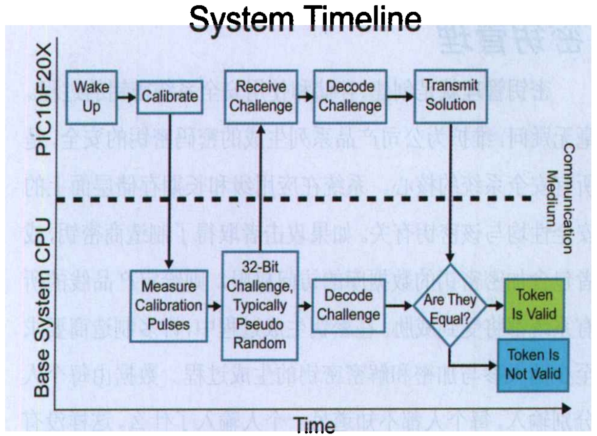
The typical timeline of the basic inquiry/response system is shown in Figure 1. According to the specific implementation plan, the timeline may include additional or different features not shown here, and some of the features shown here may also be abandoned as a whole. After the host’s processor issues a random challenge, it should wait for a short fixed time to receive a response. If a valid response is not received within a fixed time window, the host must block the token to avoid charging incompatible batteries. Figure 1 shows one-way authentication, where only the host authenticates the token.
The cryptographic algorithm decodes the challenge and calculates the response. There are several algorithms available, but the choice of algorithm still needs to be attributed to the trade-off between security and cost, complexity, and the value protected. It should be noted that even the strongest algorithms are only valuable if the rest of the system operates in a secure manner. When choosing an algorithm, it is best to use a proven algorithm, as most people lack the professional skills to develop their own algorithms.
There are two smaller block cipher algorithms available for battery authentication circuits, namely eXtendediny Encryption Algorithm (XTEA) and KEELOQ algorithm developed by Microchip Technology inc. XTEA is a common block cipher algorithm developed by Roger Needham and David Wheeler in 1997, which uses a 128 bit key with a 64 bit ciphertext and is known for its compactness and simplicity. XTEA is very suitable for processors that primarily use assembly language.
KEELOQ technology is a patented algorithm that has been used for over ten years and is widely used in applications ranging from garage door openers to passive keyless access control systems. The KEELOQ algorithm uses 64 bit ciphertext and has 32 bit ciphertext. The KEELOQ technology requires even less program memory and RAM than XTEA, but it does take longer to calculate the solution.
Based on the application of these algorithms in battery authentication, the host processor can be “trained” to know which batteries are intended for use by the charging system. “Training” can be completed by consumers, which requires them to bring their portable devices to authorized dealers and let the terminal system “recognize” its battery. In addition, some manufacturers will implement the solution in their handheld devices to verify the battery. This verification step will be executed every time the handheld device loses power. Similarly, when consumers purchase a new phone, they will set a new phone number for the phone and “train” it to adapt to the network of the communication operator. During this period, it is also possible to “train” mobile phone batteries to adapt to handheld devices and charging systems. The details of the “learning” plan depend on each system and the level of transparency that manufacturers want it to be to users. In an ideal state, each battery should be unique, so that when a battery is threatened or compromised, the entire system will not be compromised. This may include blacklisting certain numbers and blocking battery charging for specific serial numbers and password keys.
The authentication example using PIC10F microcontroller always faces the challenge of making the system more secure as long as the attacker continues to attempt to crack the security system. The use of microcontrollers for authentication can achieve a good balance between cost efficiency, time to market, and flexibility. By implementing a battery authentication scheme in a flash microcontroller, keys, algorithms, and functions can be changed without the need for hardware redesign. Microcontrollers also allow designers to introduce custom features in their systems, such as battery level measurement and safety features such as temperature and current monitoring.
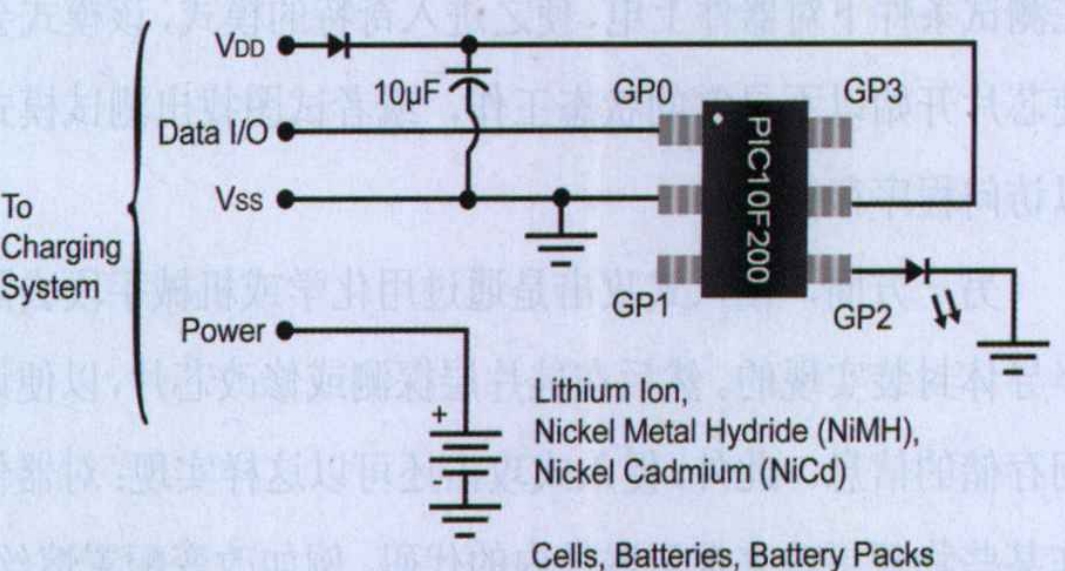
A simple decoding circuit similar to that shown in Figure 2 is a good starting point for the security scheme of the input system. Such a system can serve as a launch pad for more functional and safer solutions. This circuit can provide a certain degree of safety, as a response is required to start charging after a challenge is raised. To make the system more secure, it is convenient to add bidirectional authentication protocols, multiple decryption keys, and/or serial numbers as described above. This type of system uses Pulse Width Modulation (PWM) communication mode to achieve communication between the host and the token. If a processor with on-chip analog-to-digital converters is used, temperature detection circuits and low voltage monitoring functions can also be added to the system.
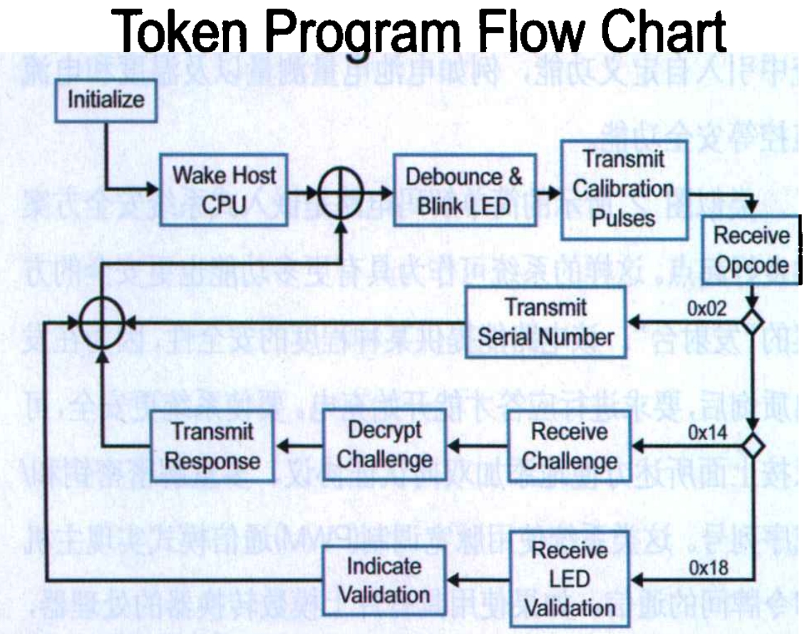
The system in Figure 2 is built using the PIC10F200 microcontroller at the circuit token end and the PIC16F877A microcontroller at the system host end. Token software is written in assembly language to accommodate the storage capacity of a 6-pin PIC10F200 device. Another reason for using assembly language is that KEELOQ technology is patented by Microchip Technology and requires the implementation of token PIC16F877A code on PIC microcontrollers to be written in C language for easy portability. This is because the host controller may vary depending on the final system. The system is designed using Microchip’s KEELOQ authentication algorithm. Figure 3 shows the process of token software.
2. Attack on integrated circuits
For battery certification, attacks typically come from entities that want to clone batteries and sell them as original accessories in the accessory market. Therefore, the goal is to attack the integrated circuits in the battery and replicate their functionality.
Usually, there are two types of attacks against security chips: non-invasive attacks and invasive attacks. Non intrusive attacks include analyzing and understanding the characteristics of integrated circuits, but maintaining the integrity of component packaging and testing semiconductors through various methods. The brute force technique is to use all known challenge excitation elements to obtain all known responses for a given element. The inquiry scheme for exhaustive attacks is usually stored in the RAM of the attacking system or some kind of database. Other non intrusive attacks include powering on the device under test conditions, causing it to enter a unique mode that causes the chip to start working in an unusual state, or attempting to find a test mode to access program memory.
On the other hand, invasive attacks are achieved by removing semiconductor packaging through chemical or mechanical means. Then detect or modify the chip at the silicon layer to access the stored information. In addition, invasive attacks can also be achieved by making certain physical changes to the device to reveal the code inside the device, such as changing configuration fuses to modify transistor properties, and even implementing reverse engineering on integrated circuits.
3. Protecting integrated circuits
The defense against exhaustive attacks is directly related to the length of ciphertext in cryptographic algorithms and the response time of the system receiving the challenge. Taking an algorithm with a ciphertext length of 32 bits as an example, for such a ciphertext length, attackers must store or compute nearly 4.3 billion combination schemes. Considering that completing a challenge/response authentication sequence typically takes about 100ms, exhaustive attacks require nearly 817 years of search to find a reliable solution. However, if the attacker is exceptionally lucky and guesses the first answer correctly, the next solution can be obtained quickly. System designers typically believe that 32-bit ciphertext or 64 bit ciphertext is large enough to meet the requirements of battery authentication systems.
Defending against invasive attacks is a factor that all semiconductor manufacturers must consider. In the continuous development of this field, semiconductor manufacturers reduce the geometric dimensions of their systems, making it more difficult for attackers to obtain distinguishable information from the silicon wafers and metal layers inside the devices, thereby making their processes safer. The system designer must ensure that all variables related to the cryptographic algorithm are not stored in RAM at the same time. The data blocks must be processed at different times to make it more difficult for the chip to detect in real-time, rather than making all information available in RAM simultaneously.
4. Key management
Key management is undoubtedly the process of creating, storing, and using security system keys. Maintaining the security of password keys generated for the company’s product line is the core of all security systems. The security of the system at both the application level and long-term storage level is related to this key. If the attacker obtains access to the manufacturer’s key or the database containing the encryption key, all systems of a given product line will be threatened. During the key generation process, many manufacturers require at least two people to participate in the encryption and decryption key generation process. The data is entered separately by each person, and no one knows what the other person entered, so no one can access the entire key combination of the company’s products.
In such a system, when generating cryptographic keys, they must be unique for each device serial number. To achieve this, combine the serial number with the manufacturer’s key or random seed values obtained through irregular binary numbers. When there are multiple encryption keys, the other keys are also combined with irregular binary numbers and accessed separately within the system at runtime. After combining the key and serial number, use encryption or decryption algorithms to scramble the numbers and generate the final password key.
Key management also allows the system to generate multiple password keys for any serial number using multiple manufacturer codes. With this security measure, the key accessed during the challenge/response process is randomly selected when the challenge is issued. This increases the complexity of the system software, but also improves the security of the system with the lowest one-time investment.
5. Conclusion
The battery certification of portable power systems can be effectively achieved using a small microcontroller in the battery pack that communicates with the host processor. This type of microcontroller combines the advantages of small size, flexible upgrades, and low cost. Effective key management and the use of cryptographic techniques (such as XTEA or KEELOQ technology) can increase the security of authentication circuits. If combined with the aforementioned tools, designers can develop low-cost and high security battery authentication systems. In summary, battery certification has three main foundations:
1) Make the cost of cracking the system higher than the value protected by the system
2) Assuming that the system will never be absolutely secure, flexibility should be injected to facilitate future upgrades and changes.
3) When deciding on a battery certification strategy, the entire system, including design, components, manufacturing, and the people who design and manufacture the system, should be considered. For example, if someone knows the key manufacturer key, using the best password scheme is of no use. In this case, all security features in the algorithm cannot prevent others from attempting to bribe that person and harm the company.