Mechanical energy is a new type of green energy, which contains a large amount of mechanical energy during human movement. The product designed in this article, namely electric shoes, can easily convert mechanical energy based on foot movement into electrical energy, and supports a variety of energy conversion methods, including walking, running, cycling, etc. It has the advantages of being green, environmentally friendly, reliable, and low-cost. The energy storage components of the power generation shoes can be separated from the shoe body, which does not affect the normal use of the shoes when charging mobile terminals. This design is convenient, flexible, and low-carbon and environmentally friendly.
1.Overall product design
People are accustomed to landing their heels first when exercising, so the position of the heels is subjected to greater force during the movement. This device is mainly designed and installed at the back half and heel of the shoe, with a power generation device and a mobile power supply at the bottom of the shoe. Among them: the power generation device is a vibration generator, which includes a magnetic core and a coil. The coil is sheathed on the magnetic core, and the sole of the shoe is equipped with a mobile power slot; The mobile power supply is connected to the power generation device through a mobile power supply slot, which is equipped with a switch limit slot and an energy collection output interface. The position of the switch limit slot on the mobile power supply slot corresponds to the position when the switch on the mobile power supply is turned off. The mobile power supply is connected to the power generation device through an energy conversion circuit, and the sole of the shoe is equipped with a circuit board chamber for placing the energy conversion circuit. The interface for collecting electrical energy output is a pin structure.
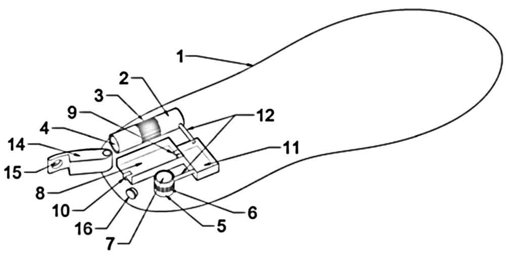
This device is designed with two miniature vibration generators. A horizontal installation, refer to component 2 shown in Figure 1; Another vertical installation, as shown in component 5 in Figure 1, is designed to receive mechanical energy from different directions at any time. Regardless of whether the foot movement is up and down or forward and backward, the mechanical energy generated by the movement can be received and effectively converted into electrical energy.
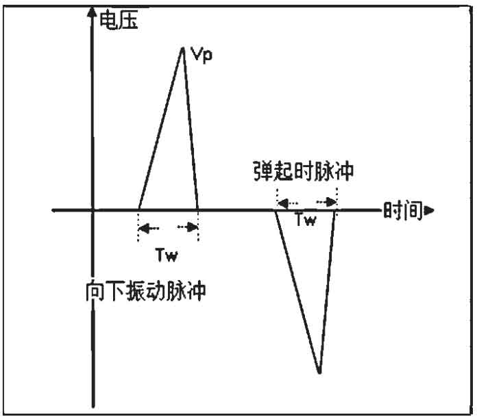
The vibration generator adopts the principle of electromagnetic induction power generation, consisting of a coil part and a rotating part. When the rotating part is subjected to external forces, it will transition from one equilibrium state to another, and each action will generate a pulse of electrical energy. The no-load waveform of the power generation module is shown in Figure 2. The pulse electrical energy generated by two vibration generators through mechanical energy conversion is rectified, collected, and transmitted to component 9 through the micro circuit board of component 11 in Figure 1. Component 9 is the interface for collecting electrical energy output, which is used to output to the built-in micro mobile power supply. Component 8 in Figure 1 is the mobile power supply.
2. Energy conversion module design
2.1 Energy conversion circuit logic
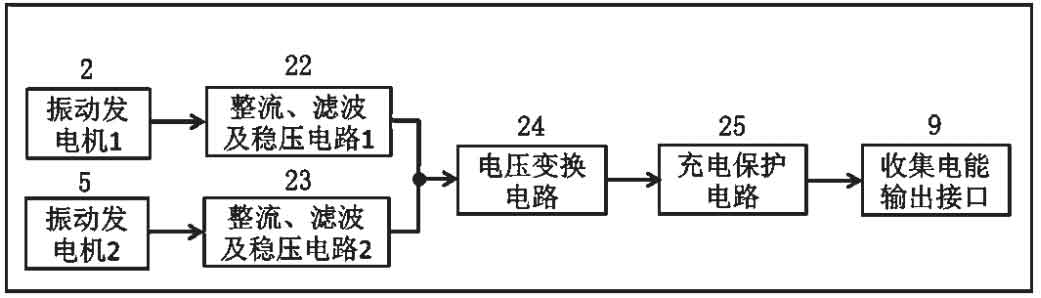
The importance of the energy conversion module as the core module of this device is self-evident. The electrical energy pulses generated by the vibration generator need to be converted into energy through four parts: rectification, energy storage, power conversion, and functional circuits. The efficiency of energy conversion and utilization depends on the design of this part of the circuit [6]. The logic diagram of the energy conversion circuit is shown in Figure 3.
2.2 Rectification Circuit Logic and Energy Conversion Circuit Principles
In the process of energy conversion, if it is necessary to use the total electrical energy during vibration downward and rebound, the rectifier circuit needs to use full bridge organization; If only the electrical energy when vibration is downward or rebounded is needed, then the rectification part only needs half bridge organization. This product is designed to use a full bridge rectification method, which can better improve energy conversion efficiency. The logic diagram of the rectifier circuit is shown in Figure 4.
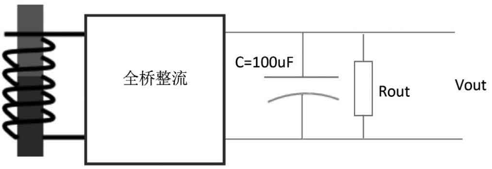
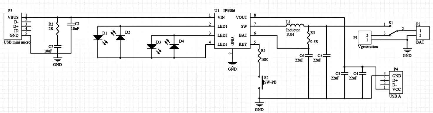
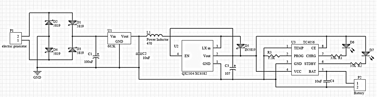
The current pulses generated by the vibration motor are rectified through a full bridge rectifier circuit, filtered, stabilized, and boosted, and then charged by a charging management chip to store electrical energy in the mobile power module. A detailed schematic diagram of the energy conversion circuit is shown in Figure 5.
3. Built in mobile power module
The design of the built-in mobile power module is shown in Figure 6. Its module is mainly installed in component 8 (mobile power slot) in Figure 1. The built-in mobile power supply can be disassembled, and it is built into the product to store electricity during exercise. When charging portable devices, it can be easily disassembled and removed at any time, making it very convenient.
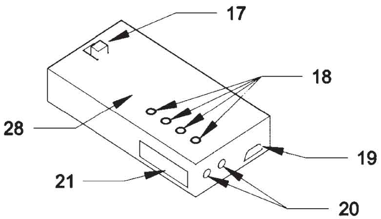
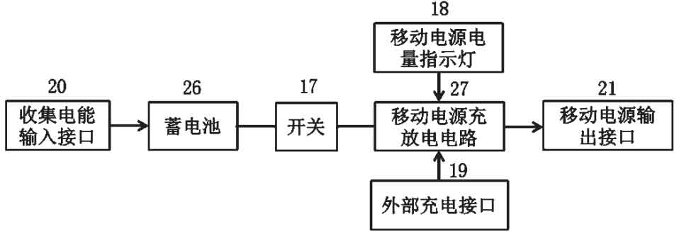
Mobile power sources include batteries, charging and discharging circuits, switches, mobile power indicator lights, external charging interfaces, input interfaces for collecting electrical energy, and output interfaces for mobile power sources. Mobile power sources can store electrical energy through the energy conversion circuit of power shoes, or they can be removed and charged by an external charger. The electric energy collection input interface of the mobile power supply can be connected to the electric energy collection output interface of the energy conversion circuit. The battery adopts a 3.7V lithium battery. After being processed by component 27 (mobile power supply charging and discharging circuit) in Figure 6, the mobile power supply outputs a voltage of 5V, which can be used for charging mobile terminals.
4. Mobile power module circuit design
The internal circuit logic of the mobile power supply is shown in Figure 7. The mobile power supply module supports two modes: external charging and built-in motion mode mechanical energy conversion electric energy charging. It can be flexibly installed and disassembled according to needs. The mobile power supply is built-in in the slot on the sole of the shoe, which is equipped with a switch limit slot. When the mobile power supply is inserted into the slot, the switch is turned off, cutting off the power bank circuit and entering the mechanical energy to electrical energy charging mode.
The management chip of the mobile power supply is responsible for charge and discharge management, and displays the remaining battery level through four indicator lights. The circuit principle inside the mobile power supply is shown in Figure 8.