With the continuous development of society and the improvement of urbanization level, people’s dependence on power supply is increasing. Power supply failures can occur at any time and are not subject to people’s will. Whether judging from industrial or civilian electricity usage, relying solely on the national power grid for power supply is far from enough. It is also necessary to have emergency power supply capabilities, especially in outdoor construction and rescue situations, where the value of emergency power supply is becoming increasingly apparent. How to provide reliable and sustainable power supply has become an urgent need, especially in extreme weather conditions such as rain and snow, stable and reliable outdoor power supply, and how to ensure electricity safety are easily overlooked issues.
At present, emergency power supply is applied in various fields, such as industry, construction, field rescue, field exploration, hospital communication, important conference venues, etc., and its role in people’s and social production is increasingly prominent. At present, there are several aspects of academic research in the field of electric power emergency response under extreme weather conditions: ① Research on the theory and technical countermeasures of electric power emergency management in disaster situations, including the design of electric power emergency management models, the construction of electric power emergency capacity evaluation index systems, the construction of electric power emergency command systems and mechanisms, and research on electric power emergency communication technology; ② On the basis of considering constraints such as power balance within the island and achieving optimization objectives such as load recovery maximization, the study of island partitioning in distribution networks containing distributed power sources; ③ Research on the optimization configuration and scheduling of mobile emergency power sources in urban distribution networks. The above research did not consider the reliability and sustainability of outdoor electricity usage under extreme weather conditions; It is of great significance to add protective mechanisms to emergency power sources, as there are no moisture-proof protection measures for their interfaces.
This design is a set of devices that can achieve emergency power interface and power body to avoid dangerous situations such as moisture, short circuit, and electric shock, while not requiring additional energy consumption. It is a set of protective mechanisms that can meet the needs of emergency power plug and play, and can also be placed on trucks as temporary emergency power vehicles. If rain and snow accumulate for a long time, the protective mechanism can be flipped to remove them, which is environmentally friendly, cost-effective, and easy to operate. It has important economic value for outdoor electricity use.
1. Protection institutions and force analysis
As shown in Figure 1, a protection mechanism designed by a 35kWh model mainly consists of 2 nitrogen springs, 1 welding protection frame, 4 deep groove ball bearings, and a fixed shaft; Two nitrogen springs are distributed at both ends of the emergency power supply, with one end connected to the protective frame and the other end connected to the emergency power supply body, connected by ball hinges; The rotation of the protective frame is supported by four sets of deep groove ball bearings and connected by a fixed shaft. The overall protective frame is welded from ordinary Q235A square tubes, with a 1.5mm SUS316 stainless steel skin welded to the upper surface. The frame and skin surfaces are coated with anti rust paint to prevent corrosion.
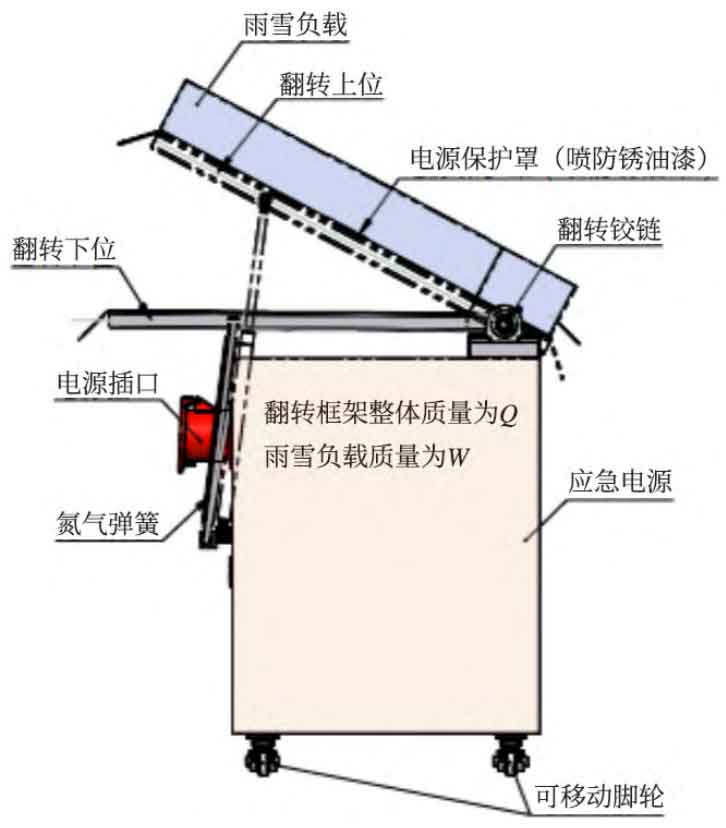
Work process: During outdoor construction, when encountering extreme weather such as rain and snow, the protective frame is manually flipped to the horizontal position (flipped down) to protect the emergency power supply body and power interface from moisture. Under normal circumstances, it can meet the outdoor electricity demand for about 3-4 days. If the frame is left outdoors for an extended period of time, it needs to be manually flipped to the upper position (flipped to the upper position), cleared of snow, and then flipped back to the horizontal position. If the power supply needs maintenance, manually flip the protective frame to the upper position. During the flipping process, the most easily damaged one is the nitrogen spring, so the force analysis of the nitrogen spring is of great significance. This project mainly analyzes the force situation of the rod end connecting the nitrogen spring and the protective frame, as shown in Figure 2.
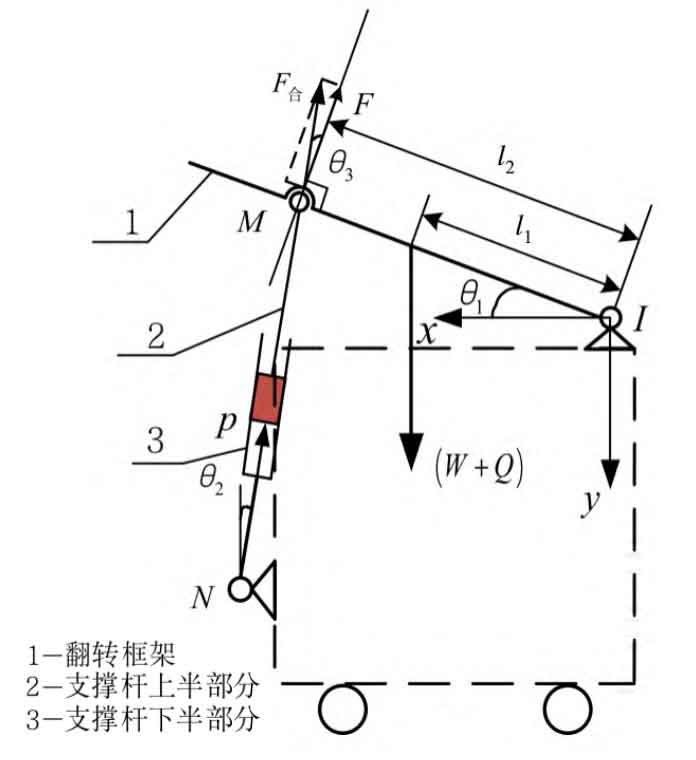
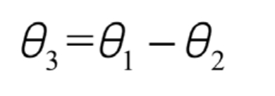
The dynamic model constructed in Figure 2 establishes a Cartesian coordinate system with the hinge point I connecting the frame and the emergency power supply body as the origin, which is the angle between the frame and the horizontal direction; The angle between the end of the nitrogen spring rod and the vertical direction; L1 is the length from the center of mass of the frame to the hinge point I, so the length of the entire frame is 2l1; L2 is the length between the frame and nitrogen spring, and the hinge point M and hinge point I of the frame; P is the pressure; F is the component force of the nitrogen spring rod end acting on the protective frame and perpendicular to the frame; The resultant force of the nitrogen spring rod end on the frame; Is the angle with F.
2. Mechanical equations
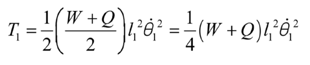
The protection mechanism designed based on a 35kWh movable emergency protection power supply is simplified into a mechanical model, and the protection framework is analyzed separately from the horizontal state to the upper state when flipped. From Figure 2, it can be seen that the kinetic energy T1 of the flipped part during the motion of the entire system is:
The potential energy of the flipped part is G1:
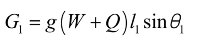
In the formula, g is the gravitational acceleration, taken as 9.8m/s ^ 2.
Due to the fact that nitrogen springs are only subjected to force at both ends and have no other external forces, they can be simplified as a two force rod model, with the applied points of force at both ends and the direction along the rod direction. The nitrogen spring shown in Figure 2 is compressed, so the rod end of the nitrogen spring is subjected to a reaction force of. The force is decomposed orthogonally along one side of the protective frame, and the force F is the numerical component perpendicular to the protective frame. Because the horizontal component does not generate a moment on hinge point I, it can be omitted from analysis. The relationship between force and force F is:
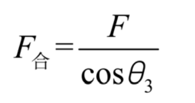
Figure 2 shows the angle between the vertical component F of the protective frame, which can be obtained from the mathematical relationship:
As can be seen from the above, considering the flipped part as a rigid body that does not deform under force, the entire flipping process from the lower critical state to the upper critical state can be seen as the flipped part rotating around a fixed axis. The differential equation for the rigid body rotating around a fixed axis is:
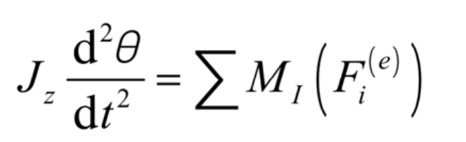
In the formula, Jz is the moment of inertia of the flipped part as a whole; The torque of each external force on hinge point I for the flipped part.
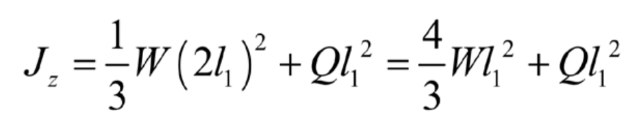
The length of the entire protective frame is 2l1, and the overall moment of inertia of the flipped part can be expressed as:
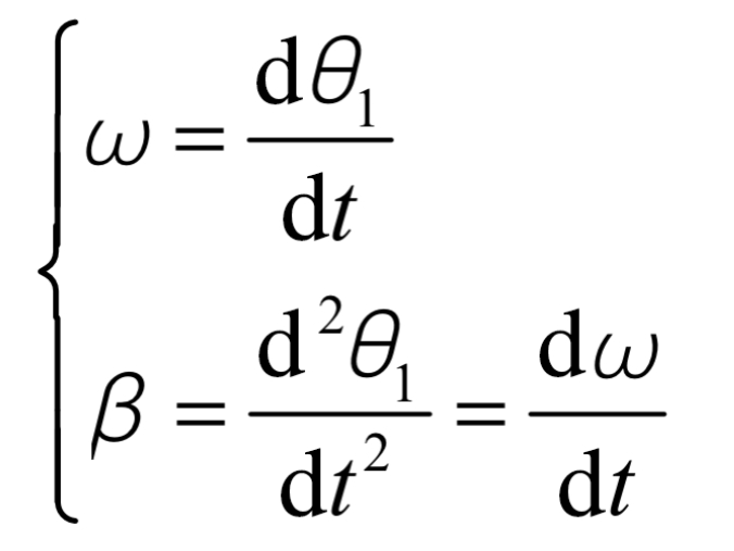
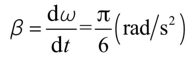
The relationship between rotation angle, angular velocity, and angular acceleration is as follows:
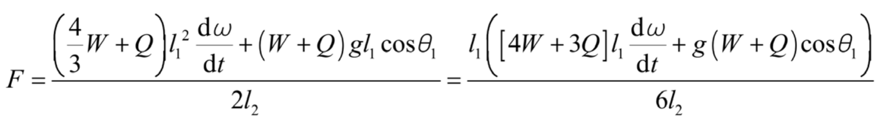
There are two moments of external forces on hinge point I in the flipping part: one is the force F of the nitrogen spring on the protective frame, with a distance of l2; The other part is the flipped part (protective frame mass and rain and snow load) (W+Q), with a distance of l1 for the applied force, so its resultant moment is:
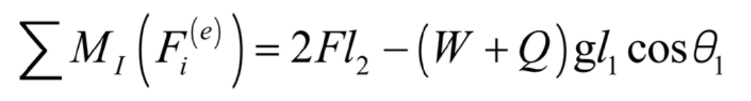
The expression for force can be obtained through the simultaneous formula:
3. Examples
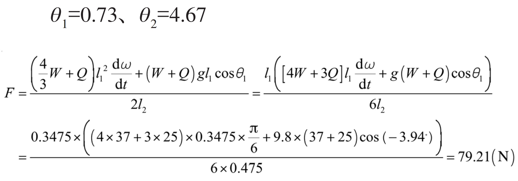
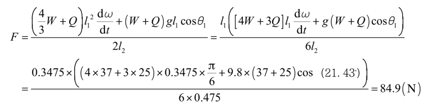
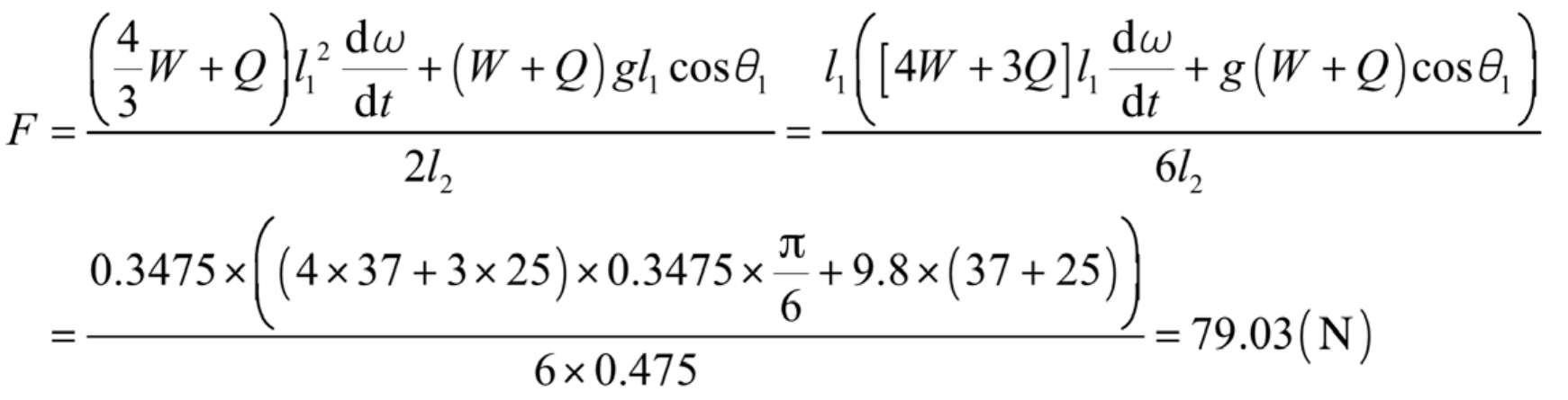
The data for each unit is as follows: the weight of the protective frame W=37kg; Rain and snow load mass Q=25kg; L1=354.7mm; L2=475mm.
Assuming:
When the protective frame is in the lowest position (lower position):
When the protective frame is at its highest position:

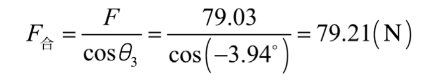
When in a special state, due to the obtuse angle between the nitrogen spring rod end and the protective frame when in the lower position, it is specified to be on the left side of F θ 3<0, when on the right side of F θ 3>0, so when placed in a lower position θ 3=-3.94. From Figure 2, it can be seen that, θ The range of variation of 3 changes from negative to positive, so there is a critical state in the middle θ 3 is 0, at which point the nitrogen spring rod end is perpendicular to the frame:
At this point, F is the minimum value, which means that the nitrogen spring rod end is subjected to the minimum force. Use mathematical model analysis software to establish a mathematical model, and the curve changes are shown in Figure 3.
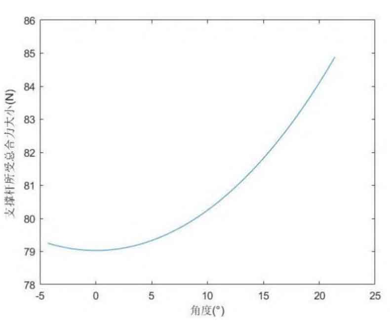
It can be seen that θ When 3=21.43, the maximum force is exerted on the rod end of the nitrogen spring, which means that the rod end is subjected to the maximum force when the protective frame is at its highest position; During the flipping process, it passed through the “dead center” of the connecting rod mechanism( θ At the position where 3 is 0, the flipping action may experience slight lag and smoothness.
4. Simulation analysis
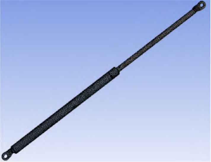
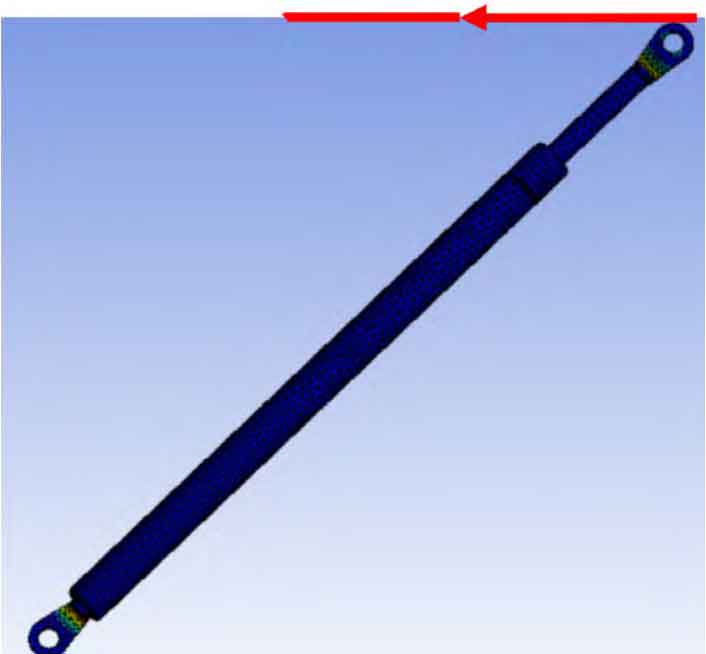
During the flipping process of the protection mechanism, in order to ensure the safety and reliability of the nitrogen spring rod end during normal operation, it is necessary to ensure that each component of the rod end can withstand the stress and strain under the maximum load condition without failure. Analyze the flipping position rod ends under three different states using finite element software. The technical parameters are shown in the table below.
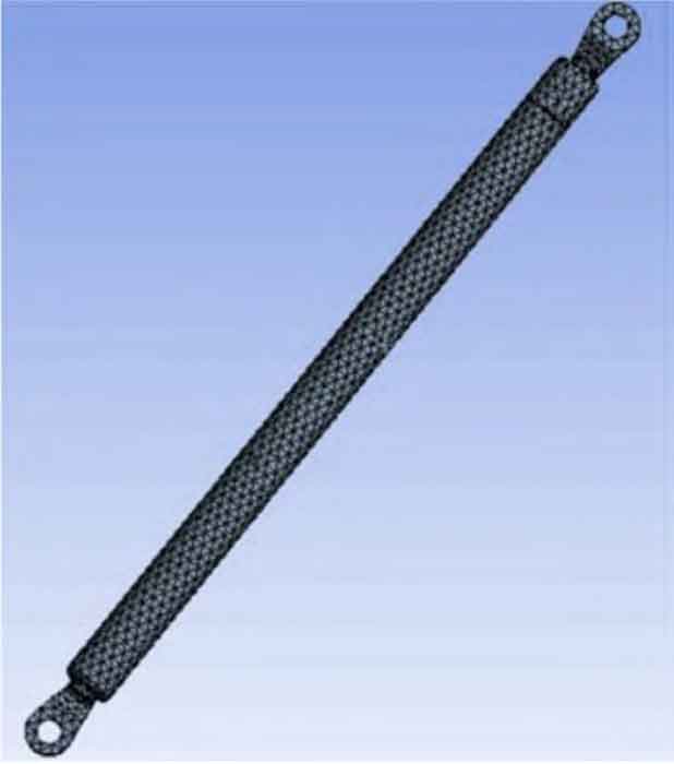
There are many components and parts in nitrogen springs. Due to the small impact of exhaust valves, seals, retaining rings, bolts, and their internal oil circuits and small structures on the overall analysis, while ensuring analysis accuracy, in order to enhance the finite element mesh division effect and improve operating speed, the model is appropriately simplified:
1) Omit the components such as the inlet and outlet, exhaust valve, seals, retaining rings, bolts, etc. of the nitrogen spring;
2) Not considering changes in material properties at hinge joints;
3) Simplified nitrogen spring cylinder body with complex structural components. When the protection mechanism is in the lowest position, the lowest end of the nitrogen spring is fixed first, and a downward force is applied along the rod end at the angle between the rod end and the flipping frame θ At 3=-3.93 °, the magnitude of the resultant force is:
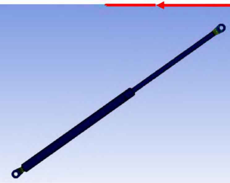
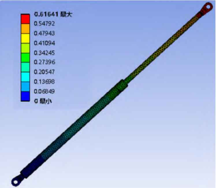
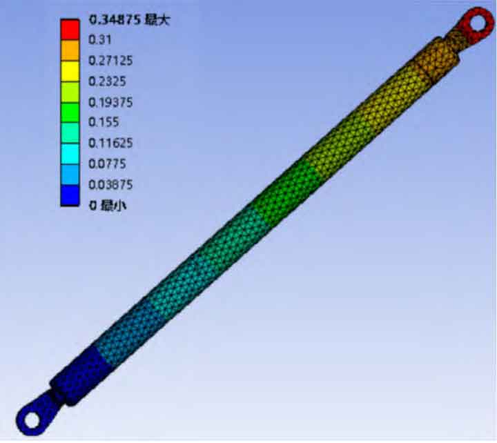
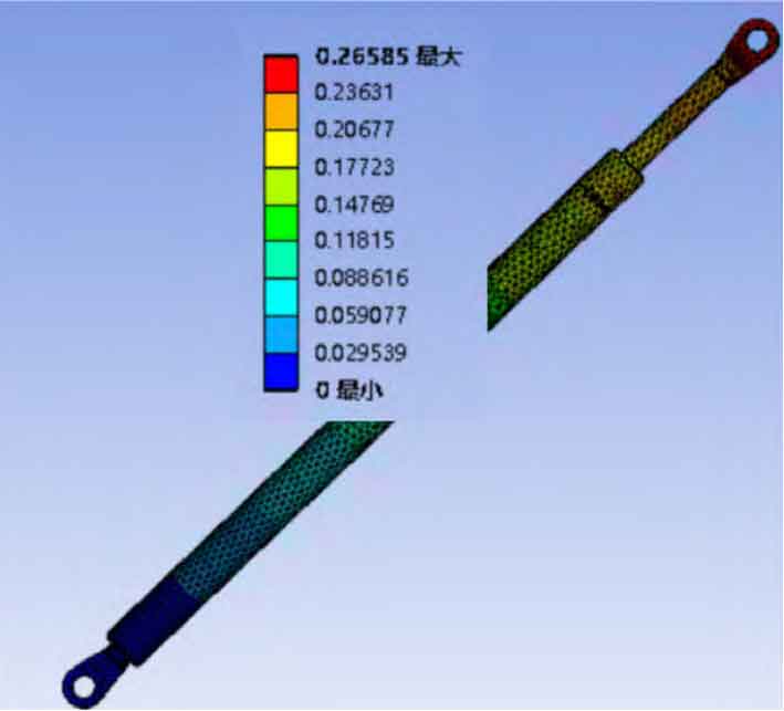
After dividing the mesh into details (see Figure 4), software analysis of the model began. Through software simulation, the analysis results of stress and strain at the end of the rod can be obtained, as shown in Figures 5 and 6. As shown in Figure 5, when the upper half of the rod end is subjected to external forces, its maximum stress is 32.78MPa. According to the material and the selected safety factor, the allowable stress is 110.3 MPa. The software analysis result is smaller than the allowable stress value of the material, thus meeting the stress verification requirements. From Figure 6, it can be seen that its maximum displacement is 0.35mm. According to calculations, it is less than the national prescribed deformation ratio of 0.3%, thus meeting the deformation requirements.
When the nitrogen spring is in a vertical state with the flipping frame, a downward force is applied along the rod end at this time θ 3=0 °, the magnitude of its resultant force is:
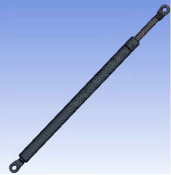
After dividing the mesh into details (see Figure 7), software analysis of the model began. Through software simulation, the analysis results of stress and strain at the end of the rod can be obtained, as shown in Figures 8 and 9. As shown in Figure 8, when the upper half of the rod end is subjected to external forces, its maximum stress is 28.51 MPa. According to the material and the selected safety factor, the allowable stress is 110.3 MPa. The software analysis result is smaller than the allowable stress value of the material, thus meeting the stress verification requirements. From Figure 9, it can be seen that its maximum displacement is 0.27mm. According to calculations, it is less than the national deformation ratio of 0.3%, thus meeting the deformation requirements.
When the nitrogen spring is in a vertical state with the flipping frame, a downward force is applied along the rod end, and the magnitude of the force is:
After dividing the mesh into details (see Figure 10), software analysis of the model began. Through software simulation, the analysis results of stress and strain at the end of the rod can be obtained, as shown in Figures 11 and 12. As shown in Figure 11, when the upper half of the rod end is subjected to an external force, its maximum stress is 35.05 MPa. According to the material and the selected safety factor, the allowable stress is 110.3 MPa. The software analysis result is smaller than the allowable stress value of the material, thus meeting the stress verification requirements. From Figure 12, it can be seen that its maximum displacement is 0.62mm. According to calculations, it is less than the national deformation ratio of 0.3%, thus meeting the deformation requirements.