
Solar energy is a new type of energy with many advantages, such as clean and pollution-free, convenient development, no need for transportation, and endless availability. In recent years, the country has attached increasing importance to environmental pollution and energy transition exploitation. Compared with other energy sources, solar energy is relatively clean and does not produce polluting substances such as exhaust gas, wastewater, and waste residue when using sunlight. Therefore, solar energy is chosen to solve the problem of insufficient energy. Due to the small current of each solar cell, it cannot meet people’s needs. Therefore, in order to obtain a large current, we usually connect the solar cells in parallel to obtain a large current; Or to obtain a higher voltage, they can be connected in series. Solar panels can convert the light energy received on their surface into electrical energy, so it is precisely because of this that the use of solar energy has become increasingly common. This design converts solar energy into electrical energy and stores it in lithium batteries to charge electrical appliances. In the long run, using solar energy to charge lithium batteries is the most suitable option.
1. System design
This design mainly utilizes light energy to be converted into electrical energy, and charges the battery through a charging board. During the charging process, there will be a diode indicator light to indicate the charging status. Starting charging is achieved through constant current fast charging, and after reaching a certain voltage value, constant voltage charging is used. During the charging process, the protection board provides protection to prevent damage to the battery caused by excessive voltage or current. After charging the battery, boost it to 5V output and charge the corresponding electrical appliances. The boost chip uses LM2577. It has a large output current and relatively high efficiency.
The design of solar portable power sources not only utilizes sunlight for direct charging, but also incorporates conventional charging methods into the design. It can be charged directly to the charging board by reducing the voltage from 220V to 5V using mains power. The entire design scheme not only incorporates new creativity but also has traditional charging methods, making it more perfect and convenient. Due to the ubiquitous sunlight, development is relatively easy and there are no transportation issues, making it more valuable for development in some poor, backward, and underdeveloped areas.
2. Circuit module design
2.1 Charging module
The main chip of the charging circuit adopts TP4056, which charges in a linear manner with constant current or constant voltage. It works in combination with USB power supply and adapter portable power supply, and is packaged in SOP8 with a heat sink at the bottom. Moreover, building the charging circuit only requires fewer external components. The charging current of the charging circuit can reach 1A, and the charging current can be adjusted through programming, so the TP4056 chip is widely used. The charging voltage of TP4056 chip is around 4.2V. If the input current of TP4056 is less than the set value, it will automatically stop the charging cycle and be in standby mode. At this time, the power supply current is 55uA. The chip also has functions such as temperature detection, undervoltage blocking, automatic recharging, and indicating charging status.
TP4056 has a preset charging voltage of 4.2V, a charging current of up to 1A, battery temperature monitoring function, portable power supply current of 55uA in standby mode, soft start limited surge current, and a 2.9V trickle charger version, without the need for MOSFETs, detection resistors, or isolation diodes.
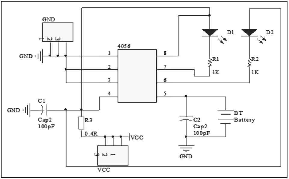
The input voltage of this circuit is between 4-8V, the output voltage is 4.2V, and the output current is 500mA. The blue light-emitting diode LED1 is used to display whether the solar panel is connected to a lithium battery, and the seven color light is used to indicate that charging is in progress. When it is fully charged, the seven color light will automatically turn off, and the blue light will light up to indicate that charging has been completed. If the temperature of the circuit is too high or too low, charging will pause. The charging circuit is shown in Figure 1.
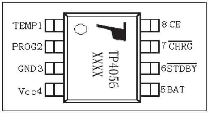
For the charging circuit composed of TP4056 chips, it adopts constant current and constant voltage charging. Without the addition of diodes and current detection resistors, the charging current can reach 1A, and the charging current can be adjusted through programming. The temperature management inside the chip automatically reduces the charging current when it exceeds 115 degrees, so there is no need to worry about the chip overheating and damage. During the charging cycle, if the CE terminal is set to a low level, the charging cycle ends. The first pin of the TP4056 chip is the input terminal for battery temperature detection, so high or low temperatures can cause damage to the battery. Its 8 pins are the input enable terminal of the chip. When the input voltage is greater than its threshold voltage and the enable terminal is at a high level, the chip begins to enter the charging state. The TP4056 pin and functional block diagram are shown in Figure 2.
2.2 Protection module
When the charging circuit is connected, as time goes on, the voltage of the charging chip begins to continuously increase. When it reaches 4.4V, DW01 believes that it is already in an overvoltage charging state, so it will immediately disconnect pin 3. The switch tube inside 8205A will close due to the lack of voltage on pin 4, and the charging circuit will disconnect, stopping the charging state. When the charging voltage is below 4.3V, pin 3 of DW01 outputs a high level again, causing the overcharge control tube in 8205A to conduct, allowing the circuit to discharge again. Short circuit protection is equivalent to adding a resistor to make the load current of the protection board reach a large current value immediately, and the protection board will immediately play a protective role.
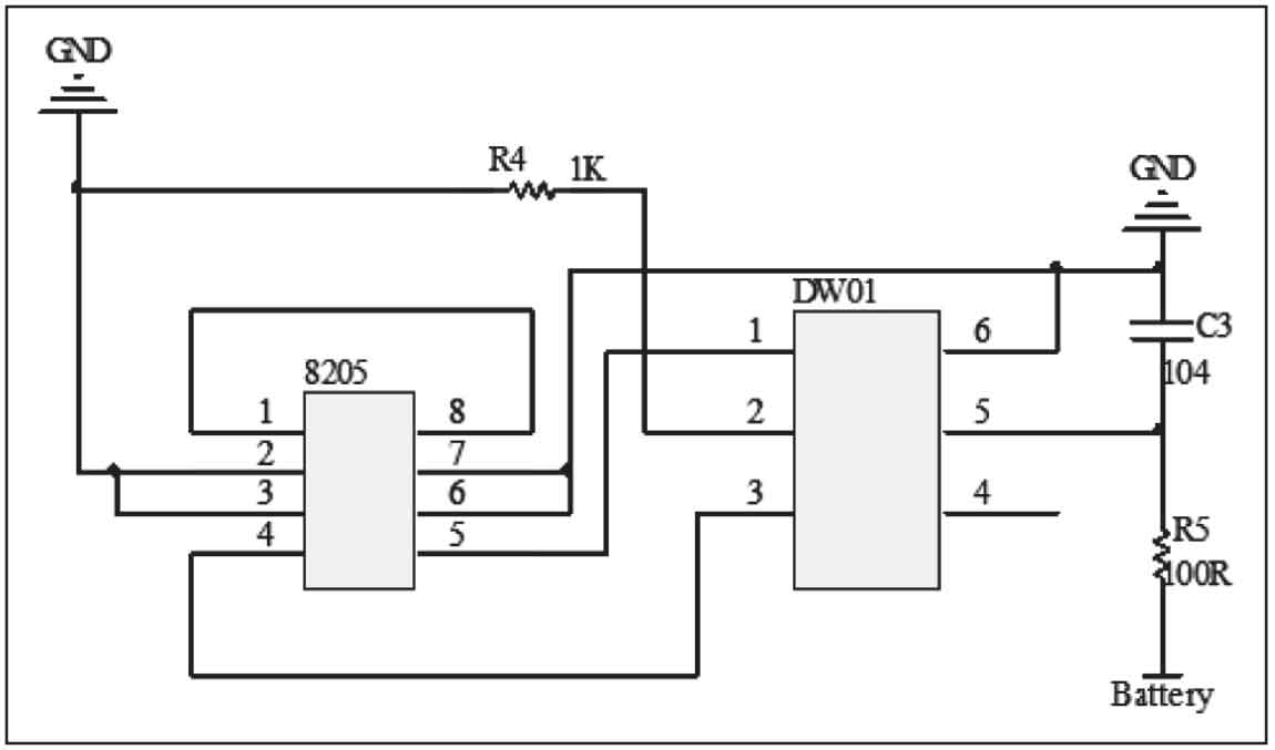
The chip for protecting the circuit consists of two chips, DW01 and 8205A. When the chip voltage is between 2.5V and 4.3V, the first and third pins of DW01 output a high level, while the second pin is a low level. Connect 8205A to DW01 to form a protective circuit. The circuit is shown in Figure 3.
2.3 Booster module
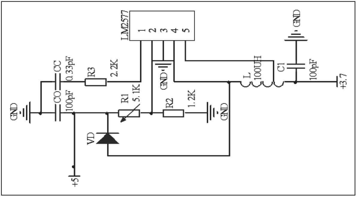
Due to the output voltage of lithium batteries being around 3.7V, in order to charge 5V appliances such as mobile phones, a boost circuit is required. The chip I have chosen is LM2577. The input voltage range of LM2577 chip is between 3.5V and 40V, which meets the design requirements. Its external circuit is relatively simple to build, with a fixed frequency oscillator of 52KHZ inside; In addition, it has high efficiency and protective functions such as overcurrent and overheating. The LM2577 output stage is an NPN type switching transistor with a withstand voltage of 65V and a rated current of 3A. The boost circuit diagram is shown in Figure 4. If the two output terminals are directly connected during testing, there is no significant overheating change due to the internal overcurrent protection of LM2577.
3. Summary
Using solar panels to convert light energy into electrical energy to charge lithium batteries, and discharging them to 5V appliances through the LM2577 boost circuit. This design utilizes the energy of sunlight, saves electricity, alleviates energy shortages, and has the advantages of clean solar energy and no pollution. Adding lithium batteries in the design temporarily stores excess energy in lithium batteries. When needed, it can be directly connected to household appliances such as mobile phones, which is more convenient and fast, and also solves the problem of long-term inability to charge outdoors in a timely manner.
Solar portable power can not only use solar panels to store electricity for lithium batteries, but also convert mains electricity into 5V during bad weather and store electricity for lithium batteries through charging circuits, in case of low electricity for mobile phones and other appliances.
(1) The price of solar panels is relatively expensive, usually 30 yuan/W. Moreover, the output voltage of the battery board is still very low, and a boost conversion is required before charging the phone.
(2) Solar portable power mainly uses solar panels to absorb light energy and convert it into electricity, so the placement of solar panels will affect their effectiveness. Therefore, when placing solar panels, try to be perpendicular to the light as much as possible.
(3) Generally, charging is done in sunlight. At this time, we try not to expose mobile phones and other appliances to direct sunlight to prevent them from aging.
(4) The efficiency of solar panels is not high, usually between 10% and 15%. Even if the efficiency of the control circuit is very high, the efficiency of the entire charger is still very low.
Suggested improvement plan: For the above shortcomings, I have adopted the use of multiple solar panels in parallel to solve the problem of insufficient sunlight, fully utilizing sunlight and increasing the current in parallel to quickly charge the portable power supply.