
Solar street lights have been widely used in urban and rural road lighting due to their advantages of energy conservation, environmental protection, no need for cables, no maintenance, and high cost-effectiveness. Solar street lights consist of several parts, including photovoltaic cells, batteries, controllers, LED lights, etc. The performance of the controller determines the overall performance of solar street lights. A smart solar street light controller was designed with AVR microcontroller ATMEGA8 as the core, which can automatically recognize and match 12V and 24V batteries, and optimize the charging and discharging management process based on environmental temperature to extend the battery’s service life; LED street lights can be set to work in modes such as timed switches and adaptive lighting intensity switches. The controller has functions such as battery over discharge and over charging, load short circuit protection, etc., to ensure the reliable operation of solar street lights.
1. Controller design principles
The system structure is shown in Figure 1. The controller mainly consists of a microcontroller system (including human-computer interaction), charge and discharge control circuit, voltage sampling circuit, temperature sensor, and DC/DC wide voltage range stabilized power supply, completing functions such as battery charging and protection, and street light power supply. The microcontroller circularly detects the voltage of the photovoltaic cell and determines whether it is day or night according to certain rules. During the day, disconnect the power supply circuit of the LED street lights and adopt corresponding charging methods based on the battery level and ambient temperature; At night, turn on the LED street light power supply circuit and monitor parameters such as battery voltage and ambient temperature to prevent excessive discharge of the battery.
2. Hardware circuit design
2.1 Charging circuit
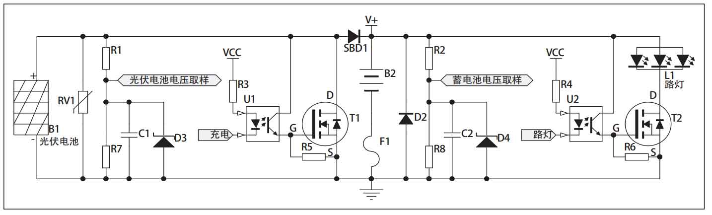
The volt ampere characteristics of photovoltaic cells are generally nonlinear, and the matching characteristics of load impedance determine the utilization efficiency of photovoltaic cells. The circuit shown in Figure 2 consists of a parallel charging topology consisting of photovoltaic cell B1, varistor RV1, diode SBD1, MOS switching transistor T1, battery B2, etc., which can achieve fast and stable charging. The MOS transistor T1 is controlled by the charging pin of the microcontroller to conduct and cut off; If it is conductive, the battery will stop charging; Cut off the circuit to charge the battery.
When the battery voltage reaches the float voltage value, the microcontroller controls the MOS transistor T1 to enter PWM modulation state, effectively protecting the battery and preventing overcharging. When selecting switch tube T1, select the maximum conduction current based on the power of the photovoltaic cell and load; Select the switching speed based on the frequency of PWM modulation. To improve the reliability of MOS transistor T1 triggering, the PWM control signal of the microcontroller is optoelectronic coupled to achieve level conversion and analog-to-digital isolation. The varistor RV1 plays a role in preventing lightning strikes and surges. Diode SBD1 is an anti reverse charging diode that prevents the battery from charging the photovoltaic cell in reverse under night or rainy conditions, and also prevents damage to the controller caused by the reverse connection of the photovoltaic cell. SBD1 uses Schottky diodes with low conduction voltage drop characteristics, which can reduce heating and improve system efficiency.
2.2 Discharge circuit
The circuit shown in Figure 2 consists of battery B2, fuse F1, diode D2, MOS transistor T2, and street lamp L1. When the “street light” control pin of the microcontroller outputs a low level, the optocoupler U2 conducts and outputs a high level, triggering the conduction of MOS transistor T2, the street light L1 lights up; On the contrary, the street lights go out. When the battery experiences overload or overcurrent during charging and discharging, the fuse F1 can quickly blow to protect the circuit from damage. The combination of fuse F1 and diode D2 can also provide protection against battery reverse connection.
2.3 Voltage sampling circuit
As shown in Figure 2, the voltage of the photovoltaic cell is divided by resistors R1 and R7 in series, filtered by C1, and protected by D3 overvoltage. It is input into the A/D conversion circuit of the microcontroller to calculate the strength of the sunlight, which serves as a signal for daytime and nighttime signals. In the same process, the battery voltage is sampled by R2, R8, C2, and D4, and then recognized by the microcontroller to manage the charging and discharging of the battery.
2.4 Microcontroller control circuit
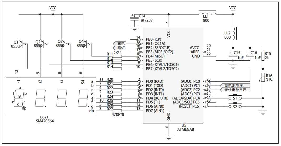
The microcontroller circuit is the core of the solar street light controller to achieve intelligent control, as shown in Figure 3. The AVR series ATMEGA8 low-power microcontroller is selected as the microcontroller, which includes an RC clock circuit and a BOD power on reset circuit. Simply connect the power pin to form the smallest system; There is a hardware PWM module inside, making it easier to write battery charging control programs. The EEPROM data power-off storage unit inside the microcontroller chip makes it more convenient for users to save data; There are 6 channels and 10 bit A/D converters inside, which can conveniently read the battery voltage and timely obtain the charging and discharging status.
The dynamic scanning display of four LED digital tubes and two touch buttons together form the human-computer interaction circuit of the system, making information reading intuitive and convenient. It can display the voltage of photovoltaic cells, battery voltage, and the working status of the controller in a touring manner, and can also modify various parameters of the controller in a menu style. In order to reduce battery energy consumption, after 20 seconds of keyless operation, the digital tube enters a sleep off state; Illuminate the display again after button operation.
The overcharge voltage and overdischarge voltage of lead-acid batteries vary with temperature. In practical applications, fixed voltage values cannot be used to determine the working status of batteries, and temperature compensation measures must be taken to protect the batteries. In Figure 3, the precision resistor R15 and NTC thermistor R16 form a temperature measurement circuit, converting temperature changes into voltage changes. The microcontroller obtains voltage values through A/D sampling, obtains corresponding environmental temperature parameters, and corrects and compensates the overcharge and over discharge voltage values of the battery to protect it.
2.5 Regulated power supply
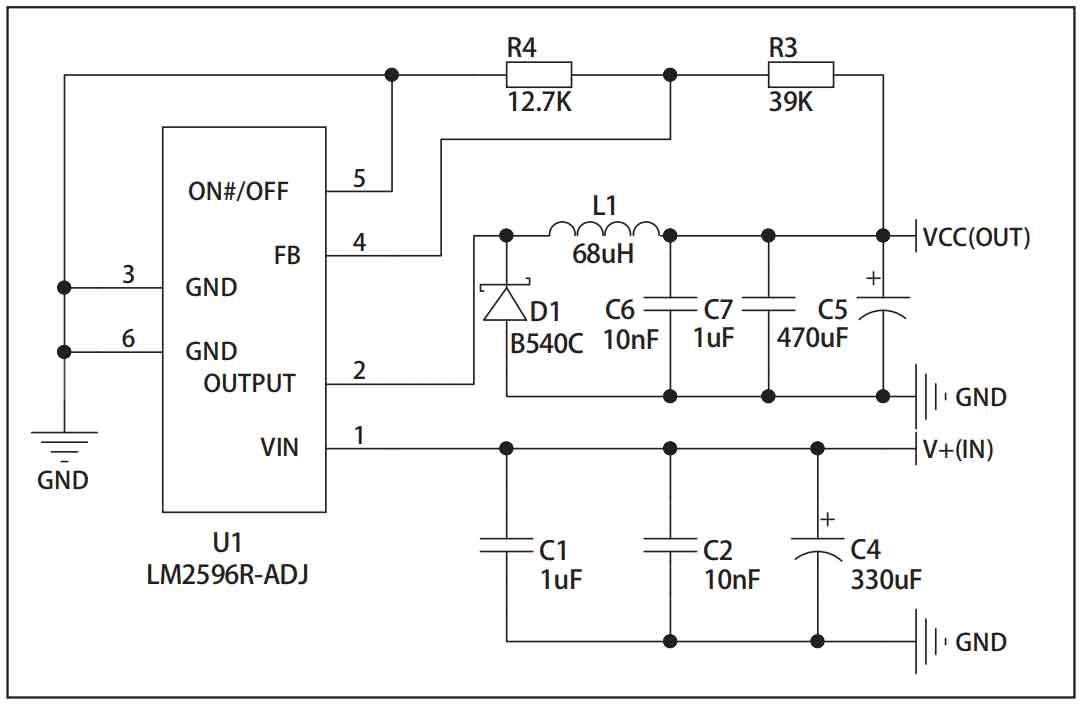
The working power supply of the solar street light controller based on a microcontroller is directly powered by a battery. Considering the adaptive 12V/24V battery of the controller, this paper designs a wide voltage stabilizing circuit composed of DC/DC chip LM2596 to obtain a stable and pure+5V DC power supply; Overcoming the drawbacks of low efficiency and high heat generation of ordinary three terminal linear regulated power supplies. The circuit is shown in Figure 4. In actual production, capacitors C1 and C2 should be placed as close as possible to the chip pins to prevent circuit oscillations.
3. Software design
Software is the soul of intelligent solar street light controllers, and its design to a certain extent determines the reliability of the entire system and the efficiency of photovoltaic power usage. The software design is based on the Windows integrated development environment WinAVR of the AVR-GCC open-source compiler and written in C language. The program of the controller mainly includes the main program, A/D conversion program, keyboard scanning program, digital tube dynamic scanning program, timed interrupt program, EEPROM read and write program, and charge and discharge management program. The main program flowchart is shown in Figure 5. After the microcontroller is started, it identifies the 12V/24V specification of the battery through voltage, loads corresponding working parameters from the EEPROM storage area, cycles to detect the output voltage of the solar cell, and enters the day and night working modes accordingly. When recognizing patterns during the day and night, the influence of ambient light should be considered; In this design, digital filtering techniques such as software delay and voltage hysteresis are mainly used to filter out interference. During the daytime working mode, the battery voltage, ambient temperature and other parameters are cyclically detected, and an appropriate PWM pulse signal is selected to achieve constant voltage charging of the battery with different amplitudes and corresponding control actions at each protection point. Similarly, during night work mode, the battery voltage, ambient temperature, and other parameters are cyclically detected. When the battery is not fully discharged, the LED street lights are lit.
4. Conclusion
The solar street light controller designed with the ATMEGA8 microcontroller as the core can optimize the charging and discharging management process based on environmental temperature and light intensity, extend the service life of the battery, automatically adapt to seasonal changes, generate low heat, have high efficiency, and low cost. The designed controller has been successfully put into production and applied in practice, with stable and reliable working performance, and has good market promotion value and technical reference value.