
1. Experimental platform
The experimental platform used in the experiment consists of a photovoltaic solar cell section, a photovoltaic inverter section, and a display section.
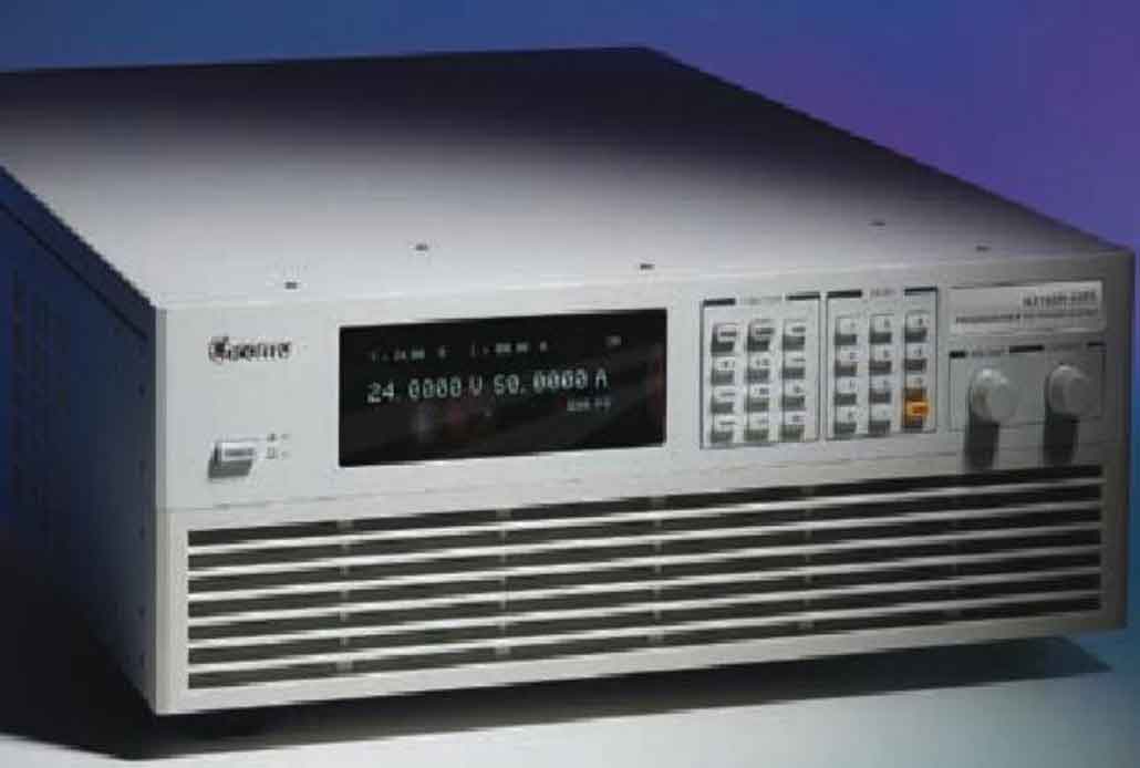
The photovoltaic solar cell part uses laboratory equipment 62150H-600S to simulate the output of the solar cell, as shown in Figure 1. The instrument can be edited with various I-V and P-V curves under different temperatures, light intensities, and shadow covering environments, and can be used to test the maximum power tracking efficiency and performance of the solar inverter in real-time. Another part of the experiment was conducted using real photovoltaic solar cells. The photovoltaic modules used had a power of 90Wp, a maximum power point voltage of 17.1V, and a maximum power current of 5.27A under standard testing conditions. Multiple identical components are connected in series in the experimental system to form a photovoltaic solar array, with a maximum output power of 870Wp, as shown in Figure 2.

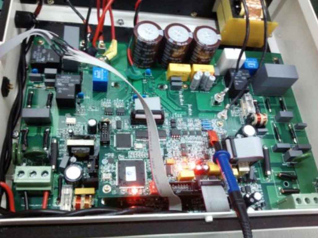
The solar inverter section is shown in Figure 3, with a corresponding output power of 3KW, consisting of a power section and a control section. The power section is composed of EMI filtering, switching power supply, boost boost and inverter main circuit, detection circuit, and protection circuit. The control part adopts the Dspic33F506 chip of microchip.
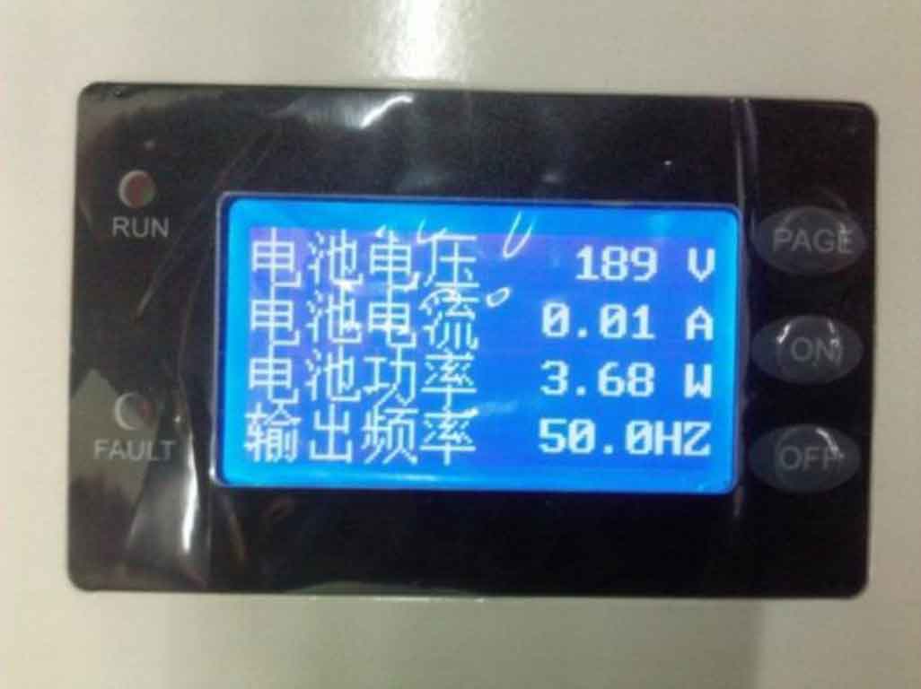
The operating status and data of the system are mainly displayed on the LCD display LMC-SSC2D16-01, as shown in Figure 4. It mainly includes four display interfaces: system operation mode interface, solar cell parameter interface, solar inverter parameter interface, and system control parameter setting interface. By pressing the ON, OFF, and PAGE buttons, parameter settings and page flipping can be performed. By using the RUN and FAIL indicator lights, it is possible to determine whether the system is operating normally.
2. Active power control experiment of solar grid connected inverter
2.1 Experimental verification of maximum power point tracking
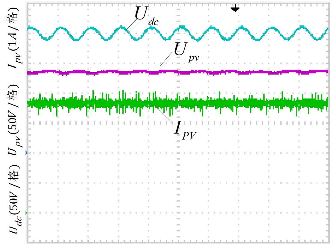
Using the photovoltaic solar cell on the roof of the laboratory as the DC input source, due to its small power, the inverter side is connected to the power grid through an isolation transformer to control the bus voltage of 200V. The variable step disturbance observation method proposed in Chapter 2 is applied to a solar inverter system, and the waveforms of the steady-state output voltage Upv, output current Ipv, and bus voltage Udc of the solar cell are shown in Figure 5. The battery current is about 3.8A, and the battery voltage is about 135V. It can be seen that through MPPT control, the output power of the solar cell is basically maintained at the current maximum power point of 513W, which proves the effectiveness of the MPPT tracking algorithm. Due to the power relationship between the front and rear stages, there is a fluctuation of 100Hz in the bus voltage, but its fluctuation amplitude is not large, around 2%, and it is basically stable at 200V.
2.2 Experimental verification of voltage and current dual closed-loop control
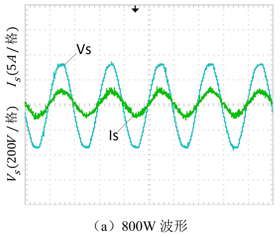
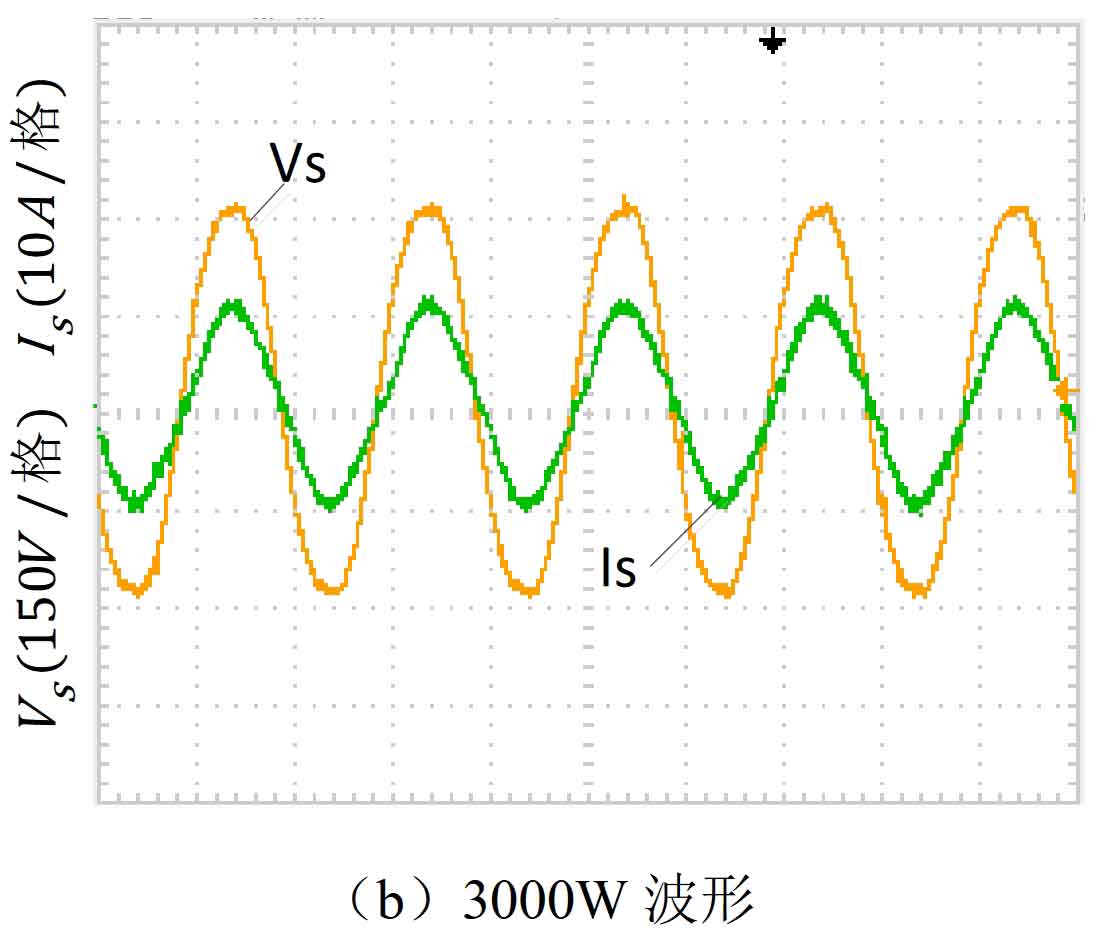
In order to verify the grid connection effect of solar inverters, a programmable DC power supply was used to simulate the output of solar cells under different input powers, and the effectiveness of active power control of solar inverters was tested. Main parameters: The grid voltage is rated at 220V (50Hz), and the DC bus voltage is controlled at 370V. When the input power of the solar cell is 800W, the experimental waveform obtained is shown in Figure 6 (a). When the input power of the solar cell is 3000W, the experimental waveform obtained is shown in Figure 6 (b). Vs is the grid voltage, Is is the output curve of the grid connected current, indicating that there is almost no phase lag between the grid connected current and the grid voltage. The frequency is basically 50Hz, and the electricity can accurately track the grid voltage with good sine degree. The harmonic content of the power grid current was tested using an intelligent electricity meter, and the values were all below 3%, meeting the requirements of the system and achieving good results.
European efficiency is an important indicator for measuring the power control of solar inverters. Assign a weight to the efficiency of solar inverters with different loads, and use the sum of the weights to characterize the efficiency of Europe. The calculation formula is as follows:
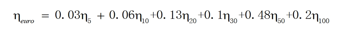
among η The operating efficiency of the solar inverter when the output power of the solar inverter is n% of the rated power, and the coefficient in front of it is the weight of this power. In the experiment, adjust the output power of the solar cell to obtain the output power values of the solar inverter at different power levels, and then test the European efficiency of the solar inverter, as shown in Table 1.
| 5% | 10% | 20% | 30% | 50% | 100% | |
| Input power (w) | 137.00 | 324.78 | 595.00 | 877.54 | 1596.4 | 2980.3 |
| Output power (w) | 119.80 | 293.1 | 554.6 | 845.0 | 1564.2 | 2932.3 |
| Conversion efficiency | 87.4% | 90.2% | 93.2% | 96.3% | 98.0% | 98.4% |
| European efficiency | 96.5% | 96.5% | 96.5% | 96.5% | 96.5% | 96.5% |
Although the system conversion efficiency significantly decreases when the load is less than 30% of the rated load, the probability of solar cells operating within this range is relatively small, so the impact on system performance is not significant. The calculated European efficiency of the prototype is 96.5%, which is still relatively high.
3. Reactive power control experiment of solar grid connected inverter
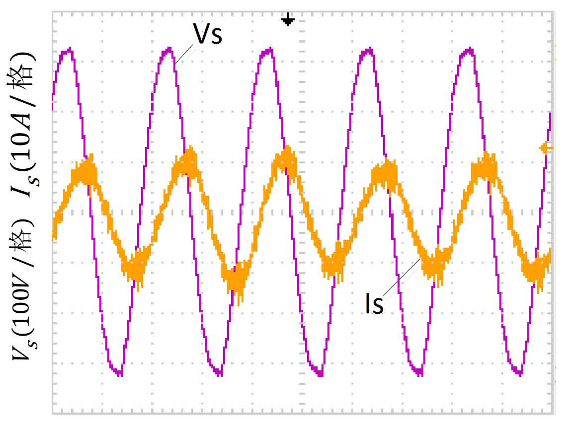
In order to verify the reactive power compensation control method proposed, a solar inverter compensation reactive power experiment was designed. The main parameters were: the grid voltage was rated at 220V AC, and the DC bus voltage was controlled at 370V. Control the phase lag of the inverter output current and the grid voltage by one β From an angle, obtain the waveform shown in Figure 7, where Vs represents the grid voltage and Is represents the grid connected current. From Figure 7, it can be seen that the grid connected current lags behind the grid voltage by an angle. The solar inverter outputs both active and reactive currents. When there is an inductive load, it can compensate for the reactive current of the load. Proved the effectiveness of reactive power compensation.
4. Summary
The following conclusions can be drawn from the experimental section of this chapter:
(1) The MPPT algorithm has good stability and high efficiency, with an average tracking efficiency of over 99%.
(2) The grid connected output current has high quality, with harmonic content within 3%, and can achieve the same frequency and phase as the grid voltage, with a unit power factor output. The efficiency in Europe is over 96%, and the conversion efficiency of solar inverters is excellent.
(3) A single-phase solar grid connected inverter can achieve simultaneous control of active and reactive power, compensating for the reactive power of the load.
From the above conclusions, it can be seen that the topology and control algorithm proposed in the article can ensure that the solar grid connected inverter operates in a good working state.
A study was conducted on the output power control strategy of single-phase solar grid connected inverters under laboratory conditions, mainly including active power control strategy and reactive power compensation control strategy of solar inverters. The work done in this paper is summarized as follows:
(1) A comparative analysis was conducted on the advantages and disadvantages of different topology structures of single-phase solar inverters. Based on the requirements of this project, the topology structure of a single-phase two-stage transformer free solar inverter system was established. The boost boost structure was chosen for DC/DC, and the hybrid H-bridge structure and single-stage SPWM modulation method were used for DC/AC, effectively reducing the power loss of the switching tubes and improving the efficiency of the system.
(2) Improvements have been made to the maximum power point tracking algorithm. By establishing a mathematical model of solar cells, the I-V and P-V curves of the solar cell output and the principle of maximum power point tracking are obtained. On the basis of traditional perturbation observation method, an improved perturbation observation method with variable step size is proposed through theoretical analysis. Simulation and experiments show that the improved algorithm improves the speed of maximum power tracking, reduces power oscillations at the maximum power point, and achieves a maximum power point tracking efficiency of over 99%.
(3) Studied the active power control strategy of a 3KW solar inverter. The dual closed-loop active power control strategy adopts voltage outer loop PI control and current inner loop quasi proportional resonance control, which efficiently converts the input power of solar cells into grid connected active energy and achieves unit power factor output. The effectiveness of active power control has been demonstrated by measuring the grid connected harmonic content with instruments below 3%, achieving a European efficiency of 96%, and minimal fluctuations in bus voltage.
(4) An analysis and research were conducted on the control scheme of reactive power compensation for single-phase solar inverters. A method based on sine signal integrator was proposed to construct a two-phase orthogonal load current signal, overcoming the traditional delay problem caused by directional shift. By using the instantaneous reactive power theory, the active reference current signal and the reactive reference current signal were obtained. Finally, the active control and reactive compensation were completed through dual closed-loop control. Experiments have shown that solar inverters have the ability to compensate for reactive power.
(5) We have completed the construction of a simulation and experimental platform for single-phase solar inverters, verifying the correctness of the theoretical analysis in the article.
The research on power control strategies for single-phase solar inverters has achieved certain phased results, but due to experimental conditions and time constraints, the following work still needs to be improved:
(1) Having islanding detection capability is an important indicator for grid connected solar inverters. The photovoltaic inverter in this design does not have an integrated islanding detection function, which will be the focus of future work.
(2) The solar inverter adopts a unipolar SPWM modulation method, which can reduce open loss, but the system will generate common mode current. As the system does not have an isolation transformer, control measures need to be taken to reduce the magnitude of common mode current.
(3) When the system is under light load, the harmonic content of the grid connected output current will increase. How to enhance the efficiency of solar inverters under light load still needs to be explored.