
Photovoltaic inverter system is an energy conversion device that converts the direct current output from solar cell array into alternating current that can be used for grid-connected power supply for users. The quality of electrical energy has a direct impact on users and the power grid, so it is very important to control the output power of solar inverter.This chapter focuses on single-phase bipolar solar inverter as the research object, and discusses the active power control strategy of inverter system.
1. Basic structure of single-phase photovoltaic grid-connected system circuit
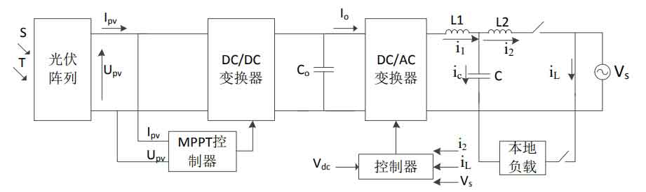
When the output rated power of a solar inverter is less than 4KW, engineering design generally tends to choose a single-phase topology with a DC side voltage of no more than 500V, as shown in Figure 1.At this time, the input voltage of the photovoltaic array is generally small, and it is necessary to use a DC/DC level boost converter to make the bus voltage meet the requirements of grid-connected size, while ensuring that the solar panel always works at the maximum output power point through MPPT control.The DC/AC level converts DC power from solar cells into AC power for the grid to be used by users.
1.1 DC/DC converter of single-phase solar inverter
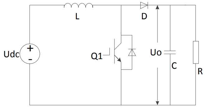
The DC/DC converter in the two-stage photovoltaic grid-connected system has high gain and a wide range of power applications.The single-phase non-isolated topologies commonly used in DC conversion stages include single-stage boost converters, interleaved parallel boost converters, and Z-source boost converters.Boost converters require fewer power devices, simple drive and design circuits, and are suitable for low-power boost conversion applications.Compared to the boost structure, the interleaved parallel boost structure has lower input current ripple, lower switching loss and conduction loss when applied to high-power applications, but requires more power devices and complex structure and control.Compared to boost converters, Z-source boost converters have a significantly higher boost capability and a simpler structure, but their current stress is increased by 2 times.Since the photovoltaic inverter system in this design is a low-power 3KW system, the boost converter is more suitable.Its structure is shown in Figure 2.
1.2 DC/AC converter for single-phase solar grid-connected inverter
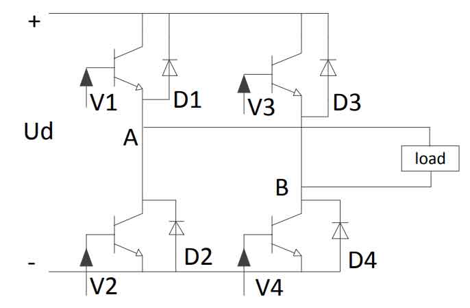
The DC/AC level of this system uses a full-bridge inverter topology, as shown in Figure 3. The control method is voltage source current control.Generally, the power grid can be approximately equivalent to an infinite AC voltage source with a certain amplitude. Using output current control, changing the phase and amplitude of the inverter side current can change the magnitude of the active and reactive currents output by the inverter, reducing the complexity of control.Solar inverters often use PWM control technology to obtain the desired waveform equivalently.Common PWM control methods include SPWM control, hysteresis comparison method, etc. Compared to the hysteresis comparison method, SPWM control has a fixed switching frequency, small harmonic output current, and relatively easy design of the network side filter circuit.Therefore, this design uses SPWM modulation.
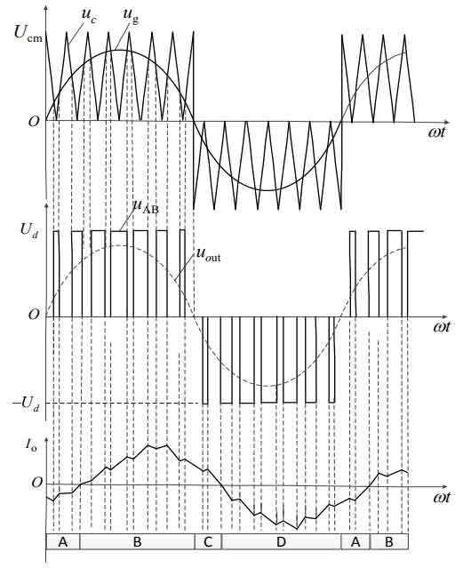
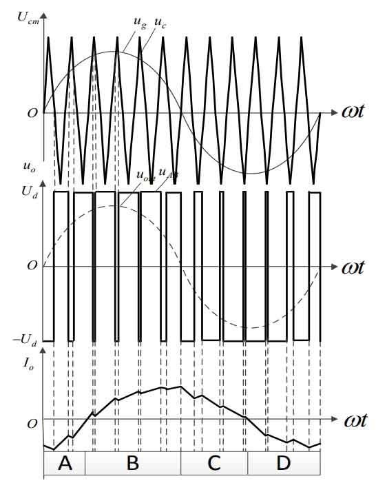
SPWM generally includes two modulation methods: unipolar and bipolar, as shown in Figures 4 and 5.Bipolar modulation has higher switching losses than unipolar modulation, resulting in increased EMI, even harmonics, and decreased circuit efficiency.Therefore, this design uses unipolar SPWM modulation.In order to further improve the overall efficiency of the system and reduce costs, the topology of the system is further optimized by using a hybrid H-bridge structure.The upper arm is a low-frequency arm with a working frequency of 50Hz, which reduces switching losses and reduces high-frequency interference.The lower arm is a high-frequency arm with a working frequency of 16KHz, which performs SPWM control.
2. Optimization of maximum power point tracking algorithm
2.1 Equivalent mathematical model of solar cells
The energy of the inverter system comes entirely from solar cells. To achieve efficient power conversion, it is necessary to understand the mathematical model of photovoltaic solar panels.Many scholars have conducted extensive research on the mathematical model of solar panels, and the basic approach is to equate the solar cell to a P-N junction with the basic characteristics of a diode, resulting in a general equivalent circuit diagram of the solar cell, as shown in Figure 6.
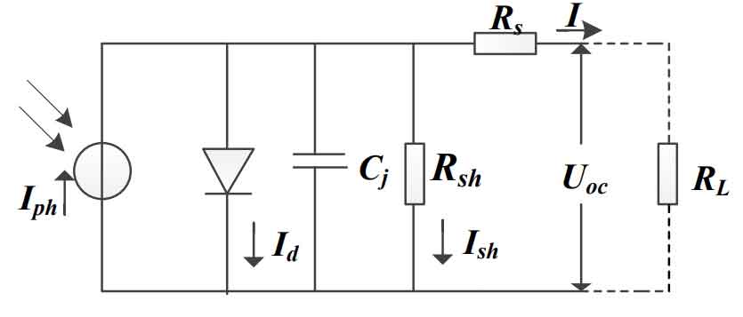
In the figure, Iph is the current generated by the photovoltaic array under sunlight, Id is the current density of the photovoltaic array, Rs is the equivalent series resistance of the photovoltaic array, Rsh is the equivalent parallel resistance of the photovoltaic array, Uoc is the output voltage of the photovoltaic array, and I is the output current of the photovoltaic array.The I-V characteristic equation of the solar cell can be obtained as follows:
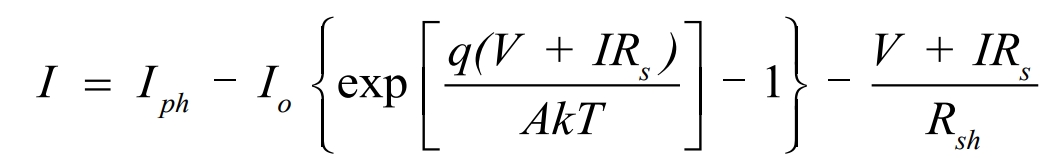
Where: Io represents the reverse saturation current of the battery;A represents the influence factor of the internal diode;T represents the absolute temperature;q is 1.6×10⁻¹⁹C;and K is 1.38×10⁻²³J/K.
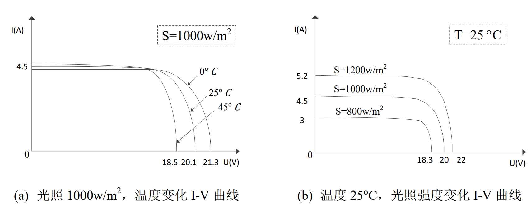
It can be seen that the V and I of the photovoltaic array have a strong nonlinear relationship, and its physical characteristics determine that the output power of the solar cell varies with factors such as light and temperature.Figure 7 shows the I-V characteristic curve of the photovoltaic array under different temperature (T) and light (S) conditions.It can be seen that under a specific external environment, there is a maximum power point for the output of the solar cell. To improve the efficiency of the solar panel, it is necessary to use maximum power point tracking (MPPT) technology to track the maximum power point of the solar cell under the current environment in real time, so that the system can output the most energy.
2.2 Comparison of maximum power tracking methods
In addition to environmental factors, the current Id, output voltage Uoc, and current I of the solar panel are also related to the size of the load resistance RL.According to the relevant knowledge of circuit theory, when the load impedance perfectly matches the impedance of the power supply, the power output of the power supply is maximized.Therefore, MPPT can be equivalent to the load impedance matching problem at the output end of the solar cell.Adjusting the duty cycle of the DC/DC level switch tube can adjust the battery output voltage, and then the battery output current will follow the change of battery voltage, which will change the impedance of the load, achieving impedance matching, that is, completing maximum power point tracking.The common maximum power point tracking methods are summarized as follows.
(1) Open circuit voltage method
Under varying light and temperature conditions, there is a certain linear relationship between the maximum power point and the open-circuit voltage, Vmpp≈k1Voc. The open-circuit voltage method can be obtained by using the coefficient k1.The size of the coefficient k1 is related to the photovoltaic solar panel, and k1 is usually between 0.71 and 0.78.When the coefficient k1 is known through the solar panel supplier, the maximum power point can be determined by periodically measuring the size of Voc.This method is very simple and low-cost to implement, and does not require a processor.However, in the case where the solar panel is partially blocked, k1 is no longer an effective coefficient for the solar panel.The value of k1 needs to be updated, which increases complexity and loss.At the same time, this method has certain defects and can cause instantaneous loss of power.
(2) Perturbation and Observation (P&O)
The perturbation observation method is a commonly used method. By perturbing the output voltage of the photovoltaic solar panel to change the output power point, and observing and comparing the output power before and after perturbation, the direction of the next perturbation can be determined. The specific perturbation method is shown in Table.Repeat the perturbation process until the maximum power point is reached, and the system will oscillate at the maximum power point.This method has clear principles, is easy to implement, and has few measured parameters.However, due to the oscillation near the maximum power point, it can lead to power loss.It can also lead to misjudgment when the external environment changes dramatically.
| Disturbance direction | Power change direction | Next disturbance direction |
| Positive | Increase | Positive |
| Forward | Decrease | Reverse |
| Reverse | Increase | Reverse |
| Reverse | Decrease | Forward |
(3) Incremental conductivity method
The principle of the incremental conductance method (IncCond) is that the slope of the power curve of the solar panel at the maximum power point is 0, the slope on the right side of the maximum power point is negative, and the slope on the left side of the maximum power point is positive.
It is known that there is a relationship between output power P, voltage V, and current I, as shown in the formula:
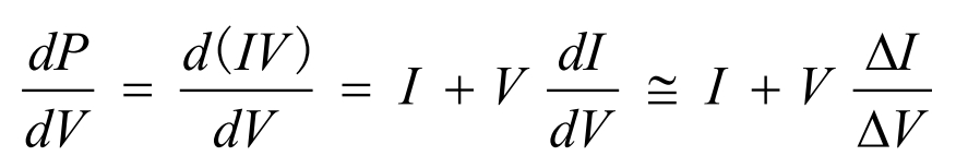
Therefore, from the above formula, we can obtain:
The maximum power point can be detected by comparing the instantaneous conductance and incremental conductance.When the maximum power point is reached, the battery voltage remains at the maximum power point until the ∆I changes. The algorithm detects the new maximum power point by increasing or decreasing the battery voltage.The magnitude of the increment determines the speed of MPP tracking. When the increment is large, the tracking speed is fast, but the system cannot accurately operate at the maximum power point and will produce oscillations. Therefore, a compromise between response speed and control accuracy is needed.When the sensor cannot achieve precise measurement, there will be errors, so the probability of satisfying the formula is very small, and there are still significant errors in practical applications.
(4) Other methods
In recent years, the application of MPPT algorithms based on fuzzy control on microcontrollers has become more and more widespread.The basic scheme is to map the power variation and duty cycle compensation to their corresponding fuzzy sets Ep and Ed, respectively, and then select the membership function based on the characteristics of the solar cell itself.Analyze the mathematical relationship between the output power and duty cycle of the photovoltaic array, determine the principles of the fuzzy decision table, and obtain the fuzzy rule table.Under varying environmental conditions, MPPT based on fuzzy control exhibits good tracking performance.However, the effectiveness of fuzzy control requires designers to have a large amount of knowledge to choose the appropriate rule table, which is complex to implement.There are also modern control theory neural network MPPT algorithms, group particle algorithms, etc., which are not described here.
2.3 Improved MPPT algorithm
Different MPPT technologies are suitable for different applications. Minimizing the response time is one of the goals of using photovoltaic arrays in residential areas, so continuous and fast tracking of the maximum power point is required.The disturbance observation method requires fewer sensors and is easy to implement, but its biggest drawback is that it can produce oscillations near the maximum power point, resulting in output power loss.The speed of maximum power point tracking is directly proportional to the size of power loss and the disturbance step size, requiring a trade-off between adjustment speed and control accuracy.Therefore, this design improves the algorithm for the disturbance observation method by adopting a variable step size maximum power point tracking method that adjusts the disturbance step size based on the distance between the current operating point and the maximum power point.That is, when the distance between the two is relatively far, the disturbance step size is increased to accelerate dynamic response and quickly approach the maximum power point.When the distance between the two is close, the disturbance step size is decreased to optimize steady-state performance and reduce power oscillations.When the power change is particularly small, the disturbance is stopped without changing the current duty cycle, thereby further reducing the power loss caused by voltage fluctuations.
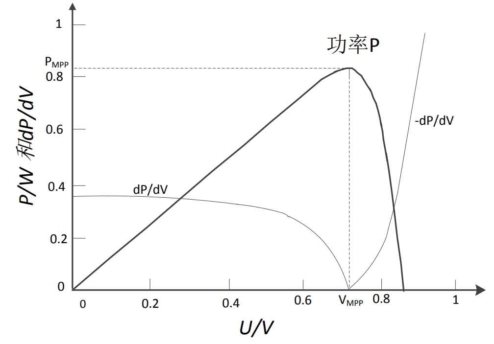
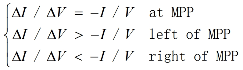
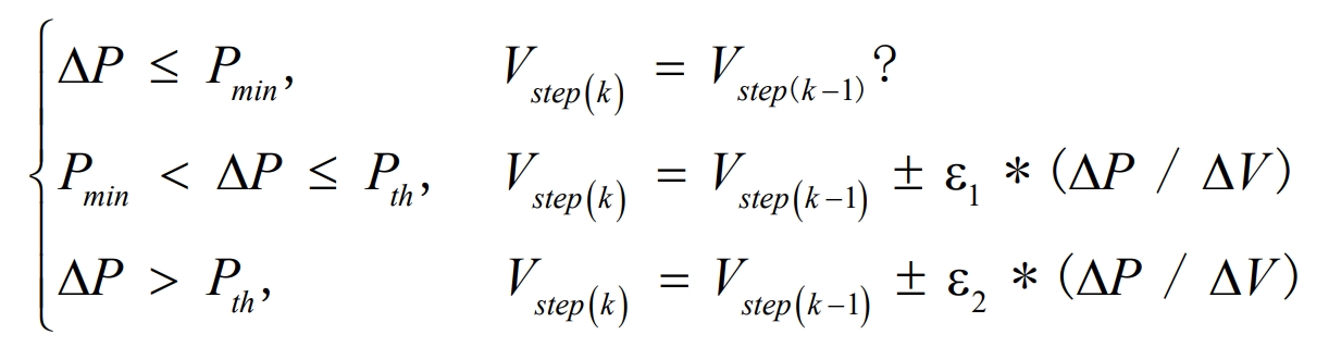
Figure 8 shows the P-V curve and dP/dV curve of the per-unitized solar cell. It can be seen that the closer to the maximum power point, the smaller the power variation dP/dV with voltage.Therefore, ε∗(dp/dV) can be used as a variable step size factor, and the control equation for variable step size maximum power point tracking is shown in equation (2.4). Where Pmin, Pth are the set power thresholds, and Pmin<Pth, ∆P, ∆V are the increments of power and voltage before and after the sampling time, and ε1, ε2 are factors selected based on experience.
Generally, there is a certain linear relationship between the maximum power point voltage and the open-circuit voltage, which is usually around 0.78 times.Therefore, when the system starts running, first sample the open-circuit voltage Voc, and take 0.78Voc as the given voltage to increase the speed of maximum power tracking.Wait until the current operating point voltage reaches the specified voltage, and then adopt the variable step size algorithm.The control diagram of the improved disturbance observer method using the constant voltage start-up method combined with the variable step size P&O method is shown in Figure 9:
3. Dual closed-loop active power control scheme for solar inverters
The goal of active power control in solar inverters is to convert all the output electrical energy from solar cells into grid-connected AC power, even if the solar inverter outputs a unity power factor.In the voltage source current control single-phase bipolar photovoltaic inverter system control method, the most commonly used method to improve the robustness, stability, and fast response of the control is dual closed-loop control: voltage inner loop cooperating with current outer loop.Therefore, this system chooses the dual closed-loop control method.
3.1 Quasi-proportional resonance control of current inner loop
The control objective of the current inner loop is to control the size of the grid-connected current to be consistent with the frequency and phase of the grid voltage. By comparing the output current of the inverter side with the given current value, the error between the two is used as the input of the current inner loop controller, forming a closed-loop control.The mathematical model of the current inner loop is shown in Figure 10.
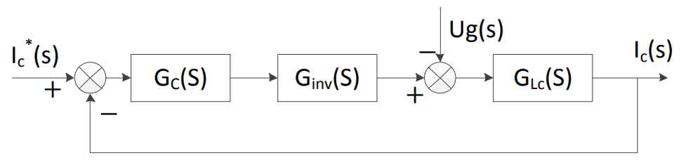
where Gc is the transfer function of the controller, Ginv is the equivalent transfer function of the solar inverter, GLC is the transfer function of the filter, and Ug(s) is the disturbance caused by the grid voltage.
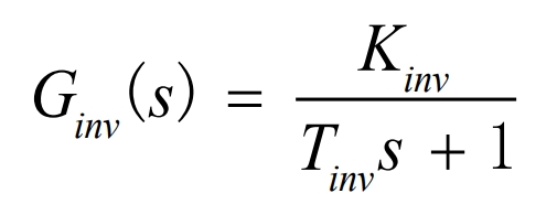
Solar inverters have high gain and low inertia characteristics.Their transfer function can be equivalently expressed as:
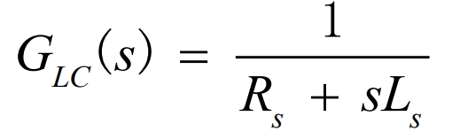
GLC(s) is the equivalent transfer function of the inverter side filtering link, as shown in the following equation:
From the analysis of the introduction section, it can be seen that the quasi-proportional resonance (QPR) control can generate a sufficiently large gain at the fundamental frequency of the power grid for the control signal, achieving zero static error under sinusoidal settings, while also reducing the impact of fluctuations in the power grid voltage frequency, with good dynamic performance. Therefore, the system uses a QPR controller.Its transfer function is expressed as:
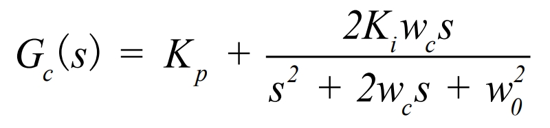
where Kp is the proportional coefficient of the controller, Ki is the resonant coefficient of the controller, w0 is the resonant frequency of the controller, and wc is the bandwidth of the controller.
As shown in Figure 10, the open-loop transfer function of the solar inverter output current can be obtained:
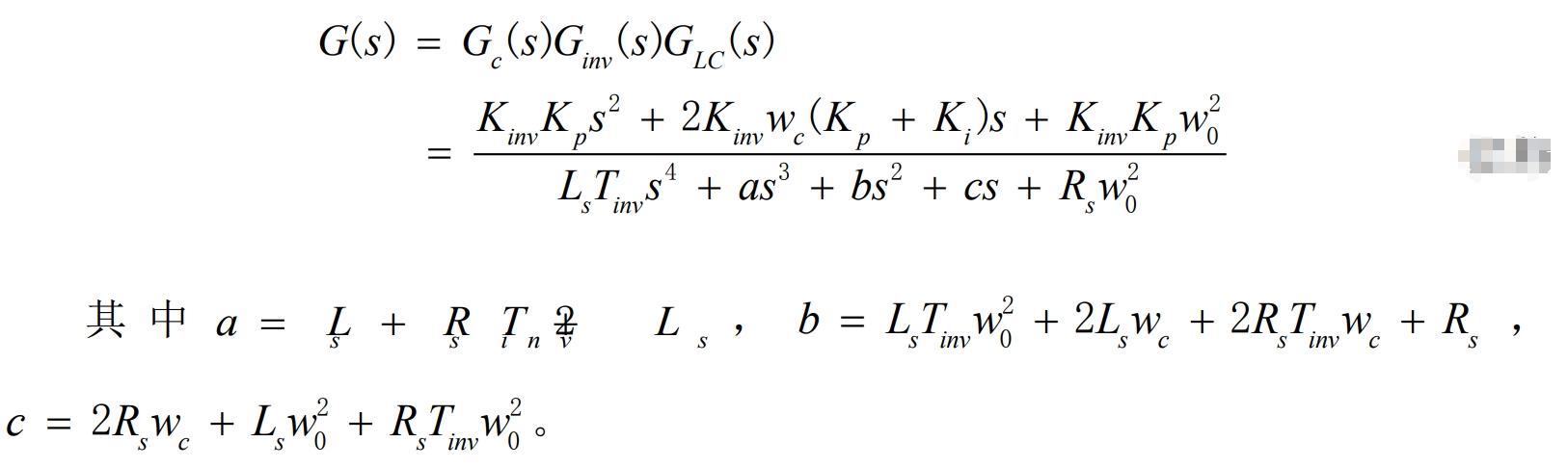
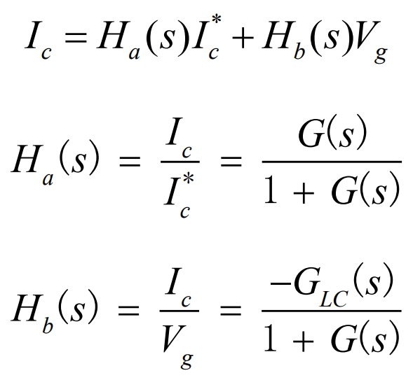
Then, the input and output relationship of the current loop can be obtained:
(1) Controller parameter selection
To achieve good control performance, the selection of controller parameters is very important.By examining the bode plot, we can investigate how the system performance is affected when Ki, Kp, and wc are each varied.When Kp=0 and Ki=60, the magnitude and phase of the QPR controller change when wc is varied.The gain and bandwidth of the controller both increase with increasing wc, but the gain at the resonant frequency remains constant, as shown in Figure 11(a).
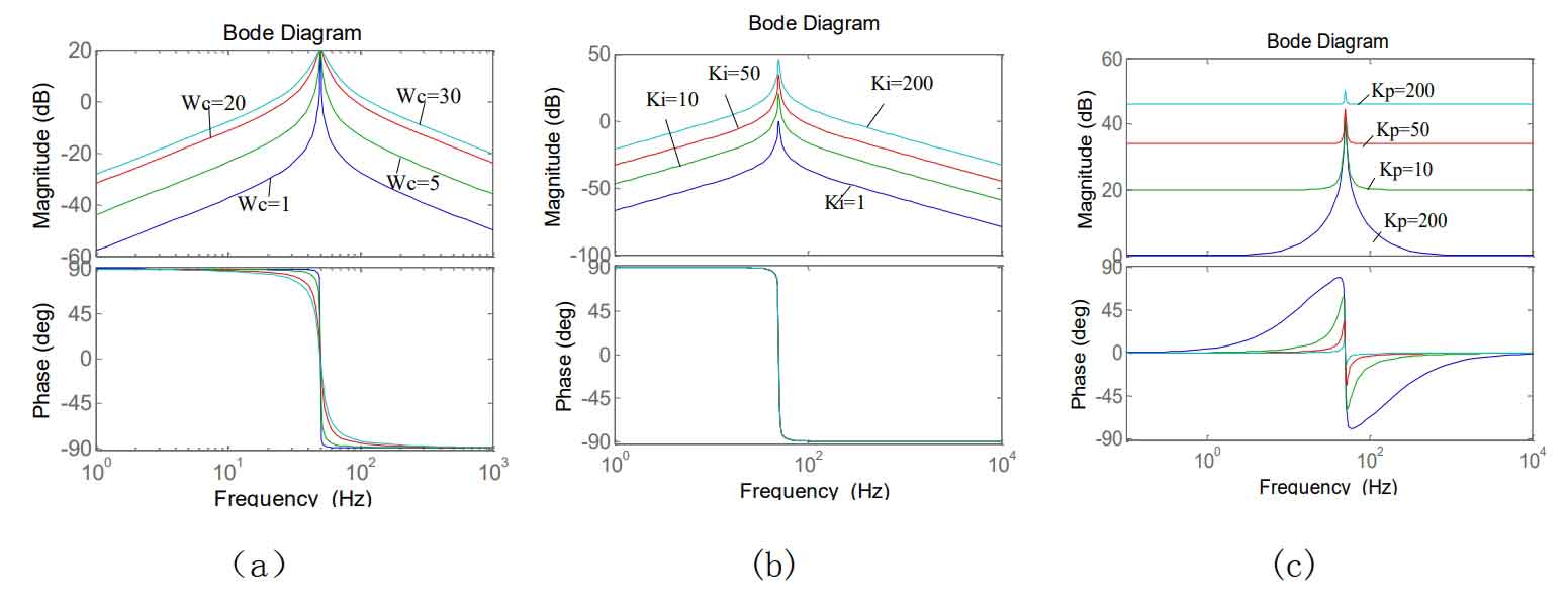
When Kp=0 and ωc=3.5, change the magnitude of Ki. As shown in Figure 11(b), the change in controller gain is proportional to Ki, but Ki does not affect the bandwidth of the controller.Therefore, changing the magnitude of Ki can change the steady-state performance of the system.
When the Kp parameter is increased, the frequency response of the controller is shown in Figure 11(c).It can be seen that Kp increases the gain of the system, but achieves a maximum at the resonant frequency.Adding the Kp parameter reduces the phase amplitude of the system, so Kp affects the stability of the system.
(2) Anti-grid interference
According to the input-output equation of the current loop, the grid voltage will have a certain degree of interference on the output current. In order to study the performance of the quasi-proportional resonant controller in suppressing grid interference, the bode plot of the closed-loop transfer function Hb(s) from grid voltage to inverter output current is obtained from the formula, as shown in Figure 12.The parameters in the formula are taken according to the actual system, Ls=4mH, Rs=1, Kinv=40, ω0=314rad/s, and the parameters of QPR are taken as Kp=4, Ki=100, ωc=3.2.From Figure 12, it can be seen that at the fundamental frequency of the grid ω=314, the system’s attenuation of grid disturbance reaches 69.4dB, which can effectively suppress grid interference.
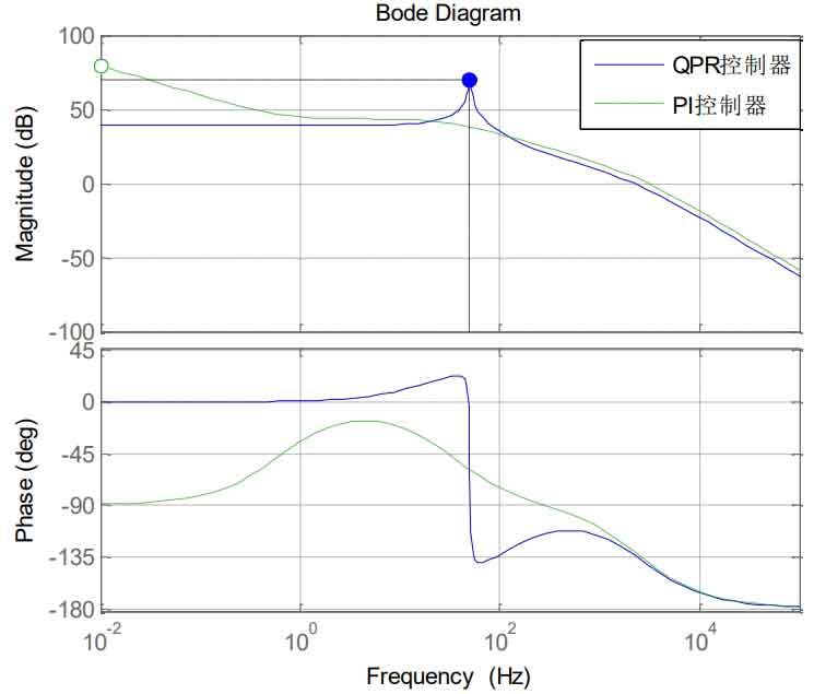
(3) Comparison between current inner loop PI control and quasi-proportional resonance control
As can be seen from the formula, the output current is related to both the given reference current and the grid voltage.Since the gain of the PI controller at the fundamental frequency is limited, the influence of voltage disturbances cannot be ignored when using the PI controller, which inevitably leads to steady-state errors.However, the gain of the QPR controller at the fundamental frequency is quite large, so it can suppress the influence of grid voltage disturbances and achieve zero steady-state error.Figure 13 is a bode plot of the open-loop frequency response of the current loop using the PI and QPR controllers, respectively. It can be seen that the gain of the QPR controller at the fundamental frequency is quite large.
3.2 Voltage outer loop PI control
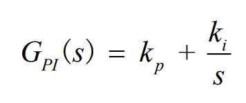
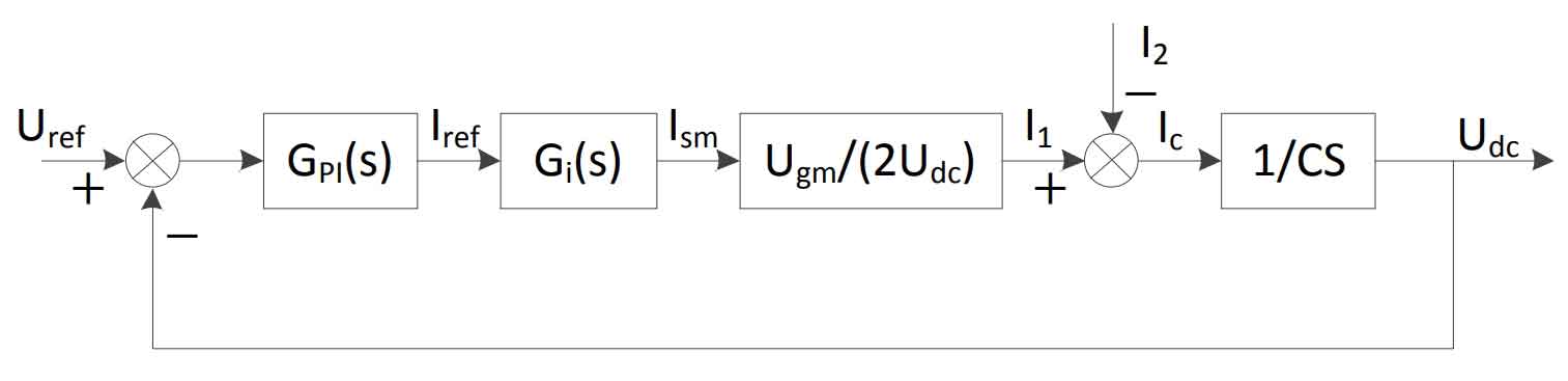
The DC side capacitor plays a role in power decoupling at the DC/DC and DC/AC levels, storing and releasing energy through charging and discharging.Controlling the stability of the bus voltage is the guarantee for stable operation and high efficiency of the system.The voltage outer loop greatly lags behind the current inner loop in terms of dynamic response speed, so the current inner loop is equivalent to the control of the grid current amplitude when designing the voltage outer loop regulator.PI regulator has no static error when tracking first-order signals and has simple parameter design, so the voltage outer loop adopts PI controller, whose transfer function is as follows:
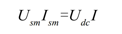
Let the input current on the inverter side be I, the DC side voltage of the solar inverter be Udc, the magnitude of the grid-side voltage be Usm, and the magnitude of the grid-connected current be Ism. From the power balance, we obtain:
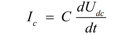
The relationship between voltage and current on the bus capacitor is:
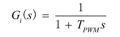
Wherein, the grid-connected current can be regarded as amplitude control, and the current controller Gi(s) can be expressed as:
Then, the control diagram of the voltage outer loop can be obtained as shown in Figure 14.
3.3 System control diagram
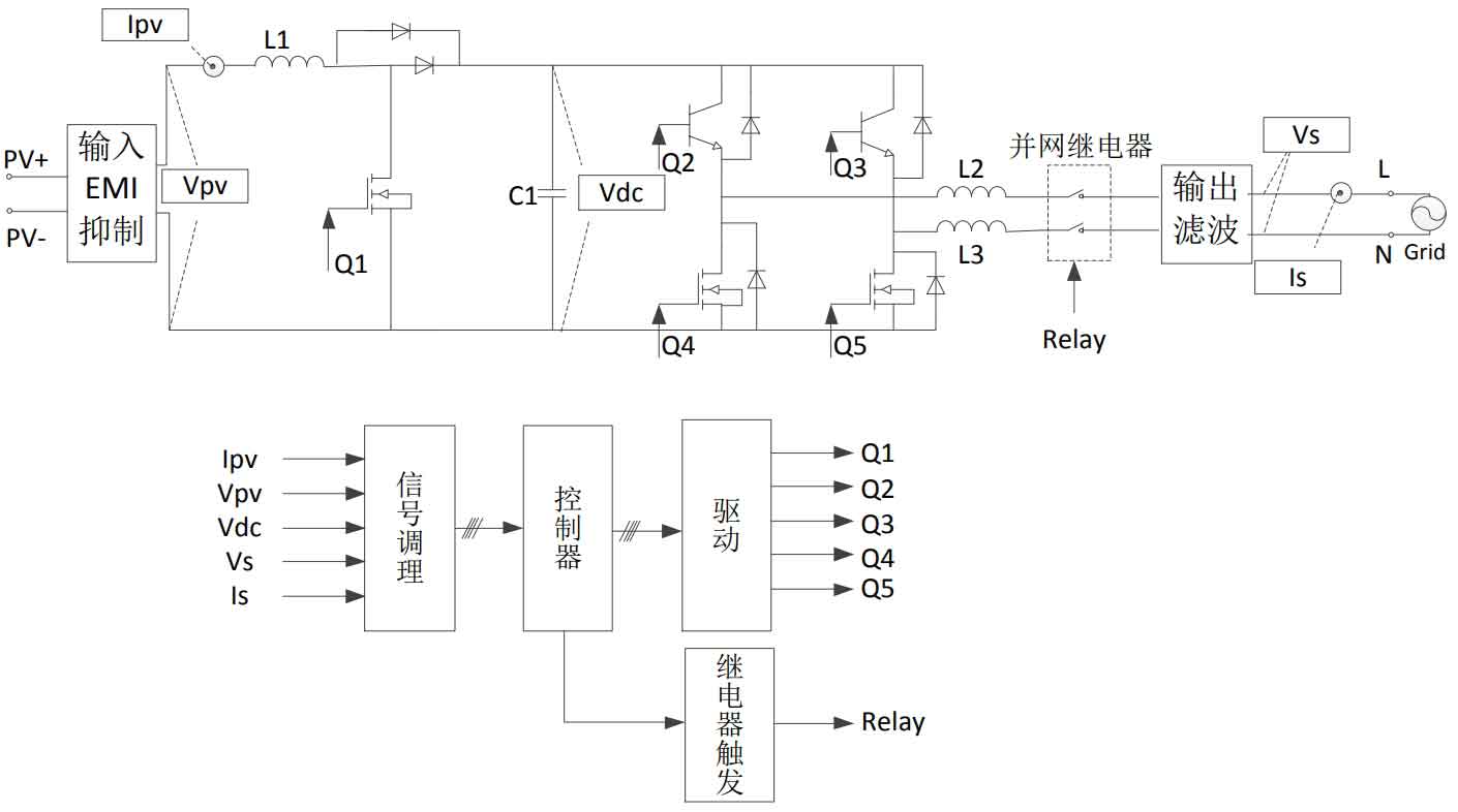
Based on the above analysis, the block diagram of the single-phase two-stage photovoltaic inverter control system is shown in Figure 15.The analog signals collected by the system include the output current Ipv, output voltage Vpv, DC voltage Vdc, grid voltage Vs, and grid-connected current Is of the solar cell.Detecting Ipv and Vpv is used in the MPPT algorithm;detecting Vdc is used to control the DC voltage through full-bridge inverter, so as to obtain a stable DC voltage;detecting Is is to ensure that the output unit power factor operates, and the solar inverter outputs all active power;detecting Vs is to lock the phase and frequency information of the grid voltage, and to use the detected grid voltage amplitude and frequency to achieve islanding detection.The drive signals of the power tube need to be filtered and isolated.
4. Summary
Based on the determination of the structure of the single-phase bipolar solar inverter, the control strategy of the active power of the solar inverter is analyzed.Firstly, the topology structure of the single-phase bipolar inverter system is established, and then the advantages and disadvantages of several commonly used MPPT algorithms are compared. A variable step-size maximum power point tracking algorithm is proposed.The theoretical analysis of the active power control scheme of the system is made. A double closed-loop control strategy is adopted, where the voltage outer loop uses PI control to maintain the stability of the bus voltage, and the current inner loop uses proportional resonance control to achieve error-free tracking of the grid current and reduce the distortion of the grid current.Finally, the overall control block diagram of the system is proposed to achieve the active power control of the system.