
With the increasing depletion of traditional energy sources and the increasing demand for energy, the use of solar energy as a new energy source has been increasing. Now, the construction of large-scale photovoltaic power plants in China has made significant progress, and the total amount of solar power generation has been in the forefront compared with other countries in the world. However, small-scale solar power plants that have been greatly developed abroad have developed slowly in China.This article designs a 500W photovoltaic off-grid inverter for household use, especially for households in areas without electricity.Through the analysis of the output of the prototype, the household solar off-grid inverter system can achieve rated power output and has high quality output voltage waveform.Through this project, the following research work has been mainly done for the photovoltaic off-grid inverter:
(1) A comprehensive study was conducted on the working principle and output characteristics of solar cells, and the design principles of three classical maximum power tracking methods for solar energy were elaborated and compared. Based on the disturbance observation method, an improved method was proposed to prevent “false judgments” due to its susceptibility to “false judgments”. The method was modeled and simulated in MATLAB/Simulink software to achieve maximum power tracking for solar energy.
(2) Through the research on the working principle of lead-acid batteries and the commonly used charging methods at this stage, combined with the actual situation of this article, a battery charging method was formulated.
(3) According to the requirements of this article, select the appropriate control chip, and study and design its peripheral circuit to ensure the safe and stable operation of the household solar off-grid inverter system.Based on the SPWM modulation principle, analyze the unipolar and bipolar modulation principles, determine the control method of the full-bridge inverter circuit, and simulate it under the matlab/simulink software. The results meet the design requirements.
(4) To ensure that the household solar off-grid inverter system operates according to design requirements, the software design of each control module of the household solar off-grid inverter system was developed, and an experimental prototype was finally built to verify the validity of this article. The household solar off-grid inverter system operates stably, with output voltage amplitude within the control range and low waveform distortion rate.
Although the output results of the experimental prototype meet the design requirements, there are still many aspects that need to be improved due to limited personal abilities:
(1) Although the disturbance observation method designed in this paper can achieve maximum power tracking for solar cells, it has a slow speed in the early stages of tracking. Moreover, due to the difficulty in simulating the misjudged environment, the feasibility of this method has only been demonstrated theoretically, and has not been verified in simulations or practical applications.
(2) Due to the use of low-voltage inverting for power frequency boosting in the household solar off-grid inverter system, the overall efficiency of the household solar off-grid inverter system is relatively low and needs further improvement.
1. Simulation
1.1 Modeling and simulation of single-pole frequency doubling SPWM modulation
The full-bridge inverter is simulated using the matlab/simulink software, and the SPWM waveform is modulated using unipolar frequency doubling. The simulation circuit is shown in Figure 1:
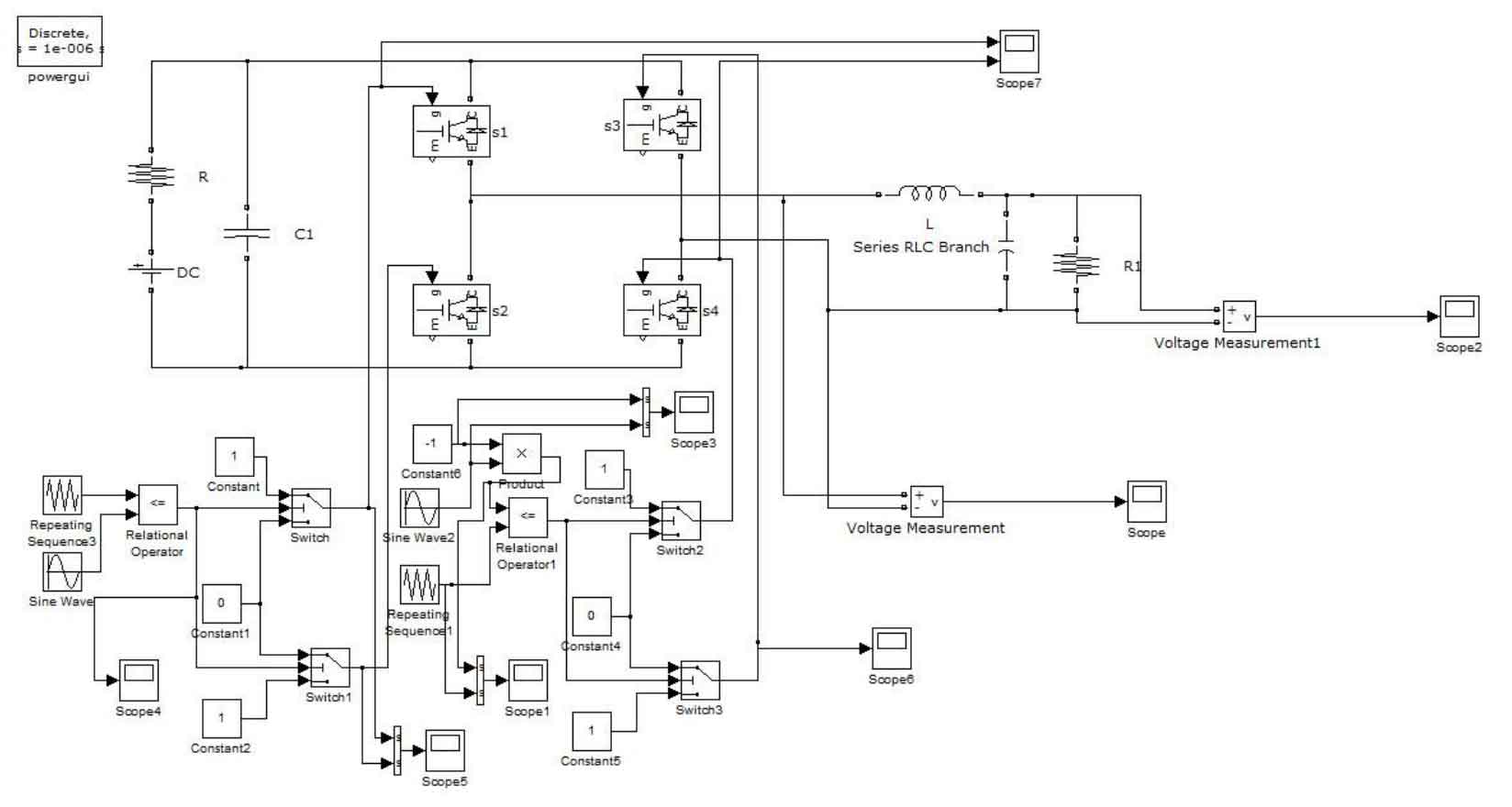
The carrier frequency is set to 10kHz, the modulation wave frequency is 50Hz, the LC filter circuit L=100μH, C=50μF, and the load R=100Ω.
In Figure 2, the drive pulse frequency of S1 and S4 is 10kHz. When the output of the filter circuit is positive, the output of the inverter circuit is a high and low level of 20kHz, which is doubled compared to the switching frequency.
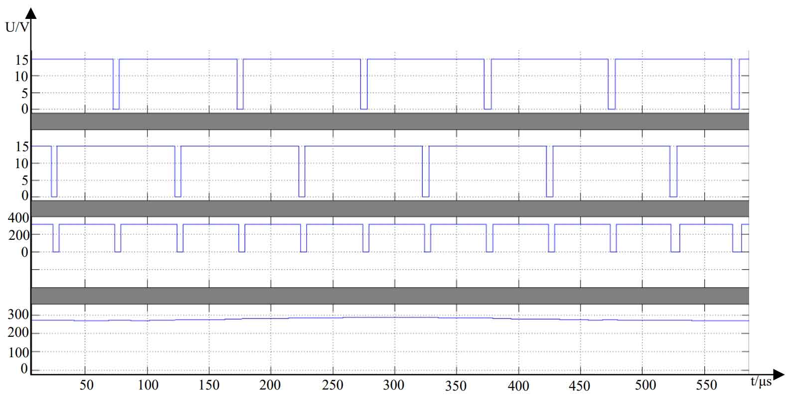
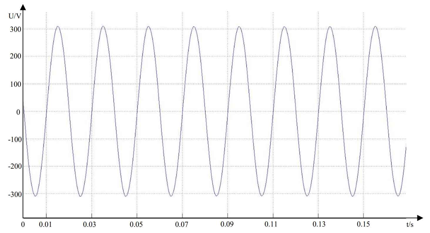
Figure 3 shows the waveform of the output voltage, with a frequency of 50Hz, a peak value of 310V, and an effective value of 220V. The waveform quality is high and meets the design requirements.
1.2 MPPT simulation of solar cells
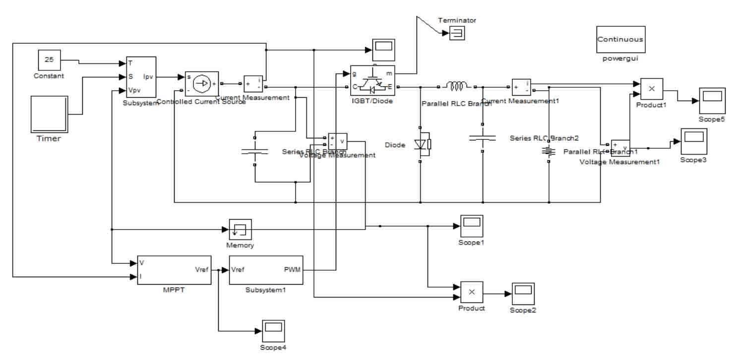
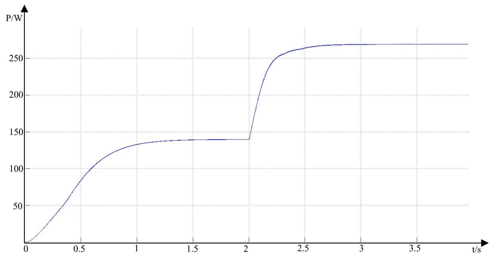
Figure 4 shows the matlab/simulink software simulation model of MPPT.The simulation time is set to 4S, the inductance L=60μH, the capacitance C=125μF, the load R=1Ω, and the switching frequency is 10kHz in the Buck circuit.The disturbance observation method and the “false judgment” prevention disturbance observation method are used, and the light intensity jumps from 600 W/m2 to 1000 W/m2 in 2S.
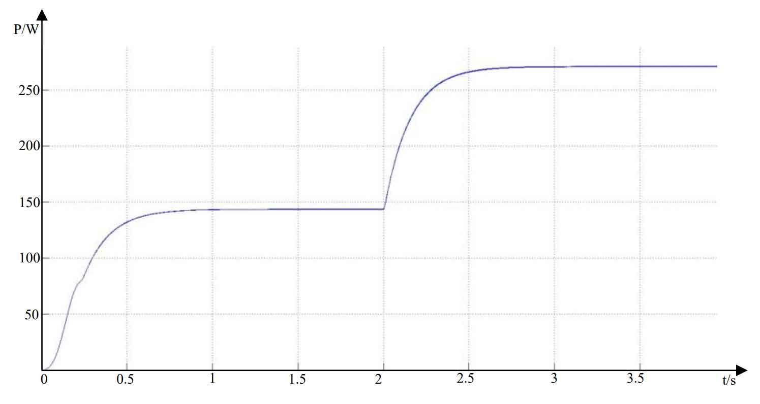
Figure 5 and Figure 6 show the circuit output power curves of the disturbance observation method and the proposed anti-misjudgment disturbance observation method, respectively.Both methods achieve MPPT. The anti-misjudgment disturbance observation method has a slower tracking speed in the initial tracking stage, but the tracking speed after the light jump is basically equal. This is due to the continuous turning back decision during the tracking process of the anti-misjudgment method.However, the tracking speed of the anti-misjudgment method is basically not affected during the long-term operation of the household solar off-grid inverter system.
2. Experimental waveform

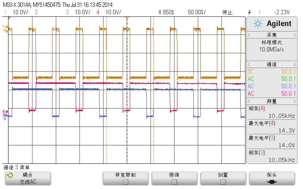
When the inverter circuit inputs a DC voltage of 28V, CH1 and CH2 in Figure 7 are the driving waveforms of the switch tubes VT1 and VT4 in Figure 10, and CH4 is the output waveform of the inverter circuit.In Figure 8, CH3 and CH4 are the driving waveforms of VT2 and VT3, and CH1 is the output waveform of the inverter circuit.When VT1 and VT4 are simultaneously turned on, the output of the inverter circuit is a positive voltage. When VT2 and VT3 are simultaneously turned on, the output of the inverter circuit is a negative voltage.The driving waveform frequency of the switch tubes is 10KHz, while the output voltage of the inverter circuit is 20KHz, which is twice the switching frequency of the switch tubes, achieving unipolar frequency doubling control.
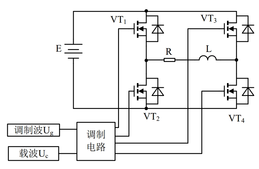
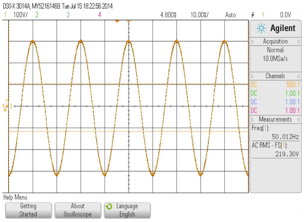
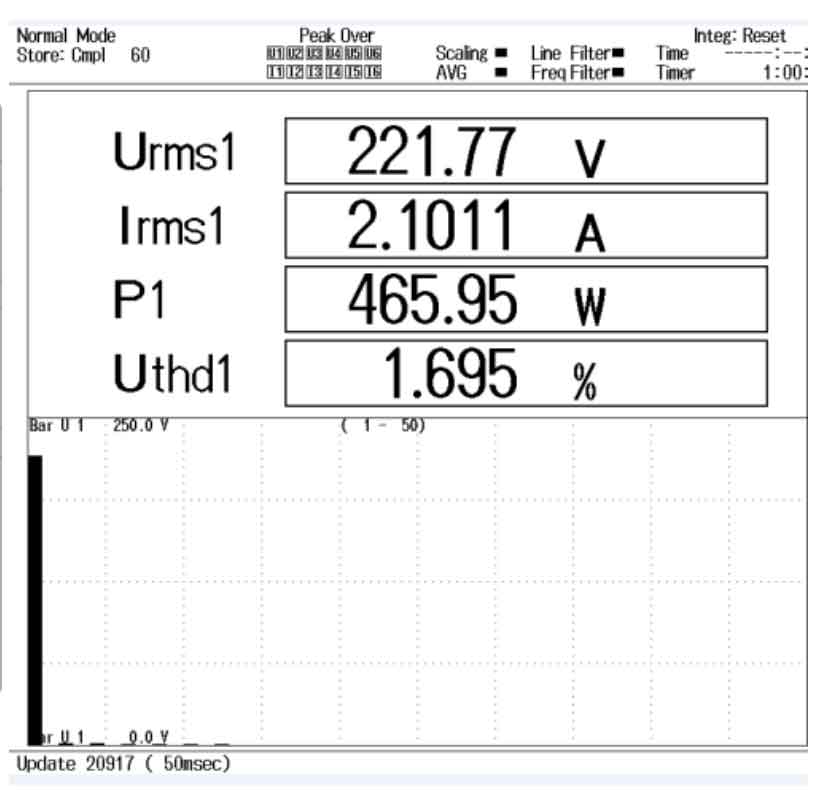
Figure 8 shows the output voltage waveform diagram of a household solar off-grid inverter system with a load of 466W, with an effective output voltage of 220V and a frequency of 50Hz.Figure 9 shows the harmonic analysis of the output voltage, with a waveform distortion rate of THD of 1.7%. The household solar off-grid inverter system can stably output high-quality sinusoidal voltage.
3. Summary of this chapter
The full-bridge inverter and MPPT were modeled in MATLAB/Simulink software and verified by simulation. The simulation results met the requirements.The output results of the built experimental prototype were analyzed, and the quality of the output waveform was very high and met the requirements.