
1. Operating principle of photovoltaic grid-connected control system
1.1 Three-phase voltage bridge inverter circuit
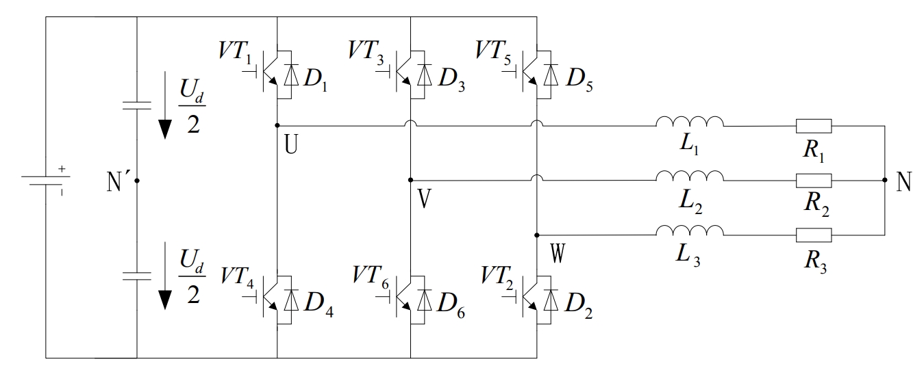
The voltage-source three-phase bridge inverter circuit using IGBT as the switching device is shown in Figure 1.The DC side of the circuit usually has only one capacitor, but for ease of analysis, two capacitors in series are drawn and an imaginary neutral point N’ is marked.
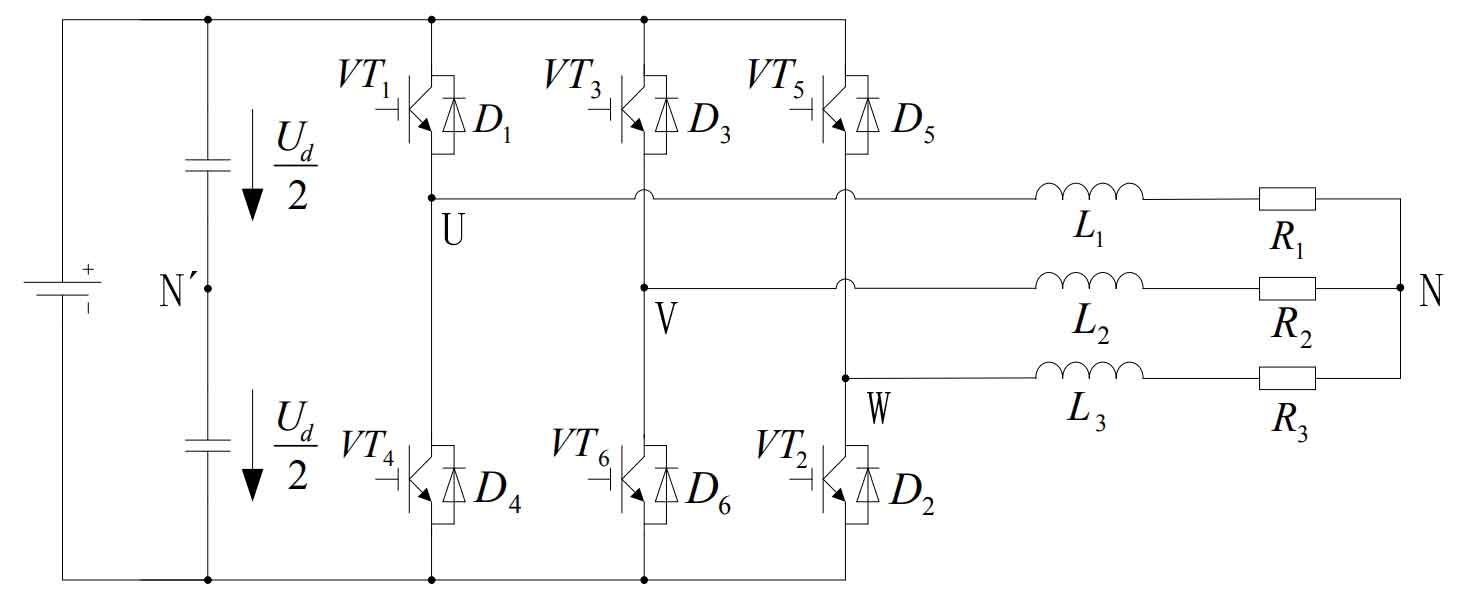
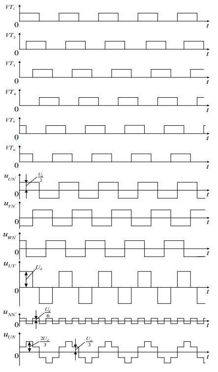
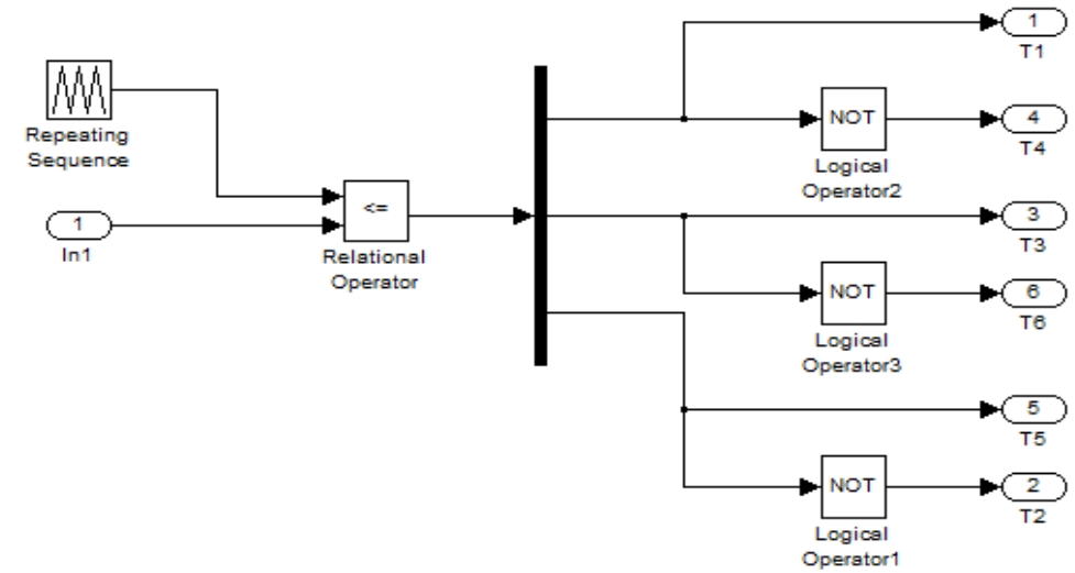
The three-phase bridge inverter circuit is a basic working mode of 180° conductive path, that is to say, the conductive angle of each bridge arm is 180°, and the same phase changes with two bridge arms alternating conduction, starting from each phase angle, and conversely, the phase difference is 120°.In this way, at any moment, the three bridge arms are working simultaneously.It can be the simultaneous conduction of the upper and lower bridge arms of one bridge arm, or the simultaneous work of the above two bridge arms and the lower bridge arm, as shown in Figure 2.Since each commutation is at the same phase change between the two bridge arms, it is also known as longitudinal commutation.
For the U-phase output, when leg 1 is conducting, uUN’ = Ud/2, and when leg 4 is conducting, uUN’ = Ud/2.
Therefore, the waveform of uUN’ is a rectangular wave with an amplitude of Ud/2.The situation for phases V and W is similar to that for phase U. The waveforms of uVN’ and uWN’ are the same as that of uUN’, except that the phase difference is 120° in sequence.The waveforms of uUN’, uVN’, and uWN’ are shown in Figure 2.
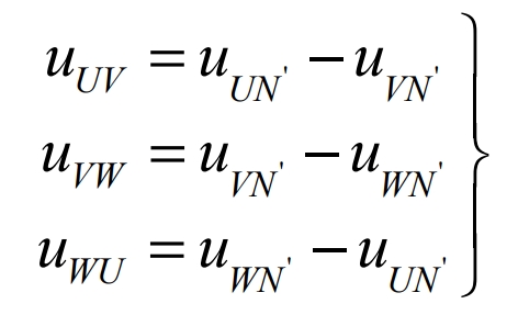
The solution formula for load line voltage uUN, uVN, and uWN is:
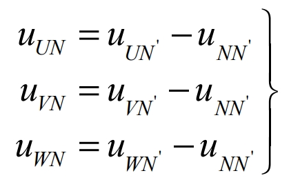
Assuming that the voltage between the load midpoint N and the DC power supply virtual midpoint N’ is uNN’, the phase voltages of each phase of the load are:
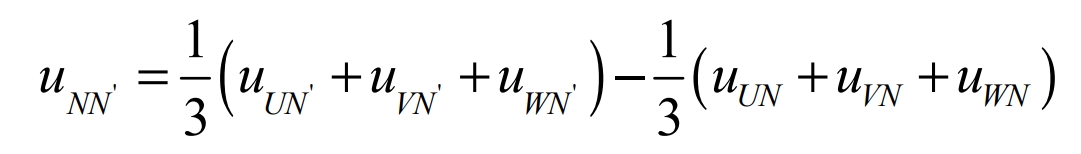
After adding and arranging the above formulas, we can obtain:
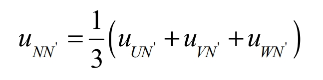
Assuming that the load is a symmetrical three-phase load, then uUN + uVN + uWN = 0 , which can be expressed as:
The waveform of uNN’ is shown in Figure 2. It is also a rectangular wave, but its frequency is 3 times the frequency of uUN’, and its amplitude is 1/3, which is Ud/6.
Figure 2 shows the waveform of uUN. The waveform shapes of uVN and uWN are the same as that of uUN, with a phase difference of 120°.
1.2 Design of three-phase photovoltaic grid-connected control system
The three-phase photovoltaic grid-connected inverter adopts a two-stage topology structure.The front-stage circuit uses a Boost circuit to achieve boosting and maximum power point tracking.The rear-stage circuit uses a three-phase bridge inverter circuit, which mainly achieves the same frequency and phase of the grid-connected current and power grid voltage, and can also control the magnitude of the grid-connected current and power.
When designing a two-stage three-phase photovoltaic grid-connected control system, the front-stage Boost circuit uses a duty cycle calculation method for control.The rear-stage three-phase full-bridge circuit controls the dual-loop control mode of the voltage inner loop and the current outer loop. The inner loop mainly implements current control according to the current voltage outer loop given command, achieving the same frequency and phase control of grid-connected current and grid voltage.The voltage outer loop controls the DC bus voltage of the grid-connected inverter, stabilizes the DC bus and provides a stable current inner loop current command.
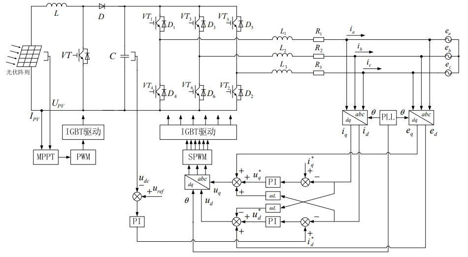
In Figure 3, the physical quantities collected by the front-stage boost circuit include: the output voltage and output current of the photovoltaic cell.The output current and output voltage of the photovoltaic cell are used for MPPT control calculations. Compared with triangular waves, the MPPT output is used to calculate the duty cycle of the PWM output control boost circuit. The PWM pulse generation module is connected to the switch tube of the boost circuit through a digital signal processor of the microcontroller, which is used to control the boost circuit to achieve maximum power point tracking and boosting.
The control of the post-stage circuit is under the control of voltage and current double closed-loop control of the inner loop, which is used for voltage closed-loop control. The collected parameter is the DC bus voltage, which is controlled to be negative by collecting the given voltage Uref of the DC bus voltage. The DC bus PI controller adjusts the error between the two, and outputs the d-axis active reference current i*d, ensuring the stability of the DC bus voltage.
1.3 Simulation parameter calculation of three-phase photovoltaic grid-connected inverter filter inductance
In the bridge inverter, there is an important component, which is the output filter inductance.The main function of the output filter inductance is to filter out the high-order harmonic current generated by the power device switch in the grid-connected current, and to generate a phase difference between the output voltage of the grid-connected inverter and the grid voltage. The grid-connected system achieves a power factor of 1 on the output side of the inverter, and the waveform is a sine wave. Through SPWM control, the output current of the photovoltaic grid-connected inverter can be in phase with the grid voltage.Selecting the appropriate inductance value is a direct factor affecting the performance of the circuit. This article studies the method of selecting the appropriate inductance value from the perspective of the ripple factor of the current.
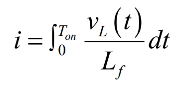
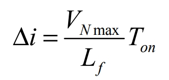
We first need to consider the relationship between the value of the output filter inductance and the magnitude of the output ripple current. Based on the fundamental voltage-current relationship for inductance, V = L di/dt, we can make the following conversion:

Wherein, vL(t) is the voltage across the inductor, and Ton is the on-time of the switch. When the output voltage approaches the peak, that is, v0(t) = VN max (VN max is the peak phase voltage), the switching period of the switch is Ts, the output current ripple reaches the maximum, and the duty cycle is D. Then,
According to the principle of volt-second balance of inductance, we obtain:
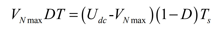
Where Udc is the DC bus voltage, we obtain:
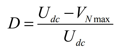
From the formula, we can obtain:
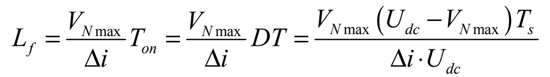
In this design, the peak phase voltage VN max = 220× √2V = 311V, the current flowing through the switch tube I = 20A, the DC bus voltage Udc = 700V, and the operating frequency of the switch tube = 10kHz z f. The period is 10 s −4 Ts = , and the relative fluctuation coefficient of the output inductor current is δ = 0.2.The formula calculation yields:
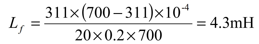
Therefore, to ensure that the actual current ripple Δi ≤ δ⋅I = 0.2×20A = 4A, the filtering inductance satisfies Lf ≥ 4.3mH. Considering the internal resistance of the filtering inductance, the design takes Lf = 4.3mH.
2. Mathematical modeling of photovoltaic grid-connected three-phase inverters
In the topology diagram of the photovoltaic grid-connected three-phase inverter shown in Figure 3, T1~6 are the six IGBT switches of the three-phase inverter bridge, L1~3 are the filter inductors of each phase, and resistors R1~3 are the internal resistances of the filter inductors L1~3, respectively. Let inductance L1 = L2 = L3 = L and resistance R1 = R2 = R3 = R, and establish a mathematical model of the photovoltaic grid-connected three-phase inverter:
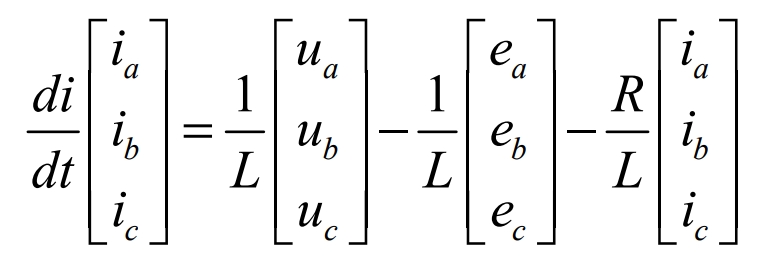
Among them, ia, ib, ic are grid-connected currents, ea, eb, ec are grid-connected voltages, ua, ub, uc are inverter output voltage.
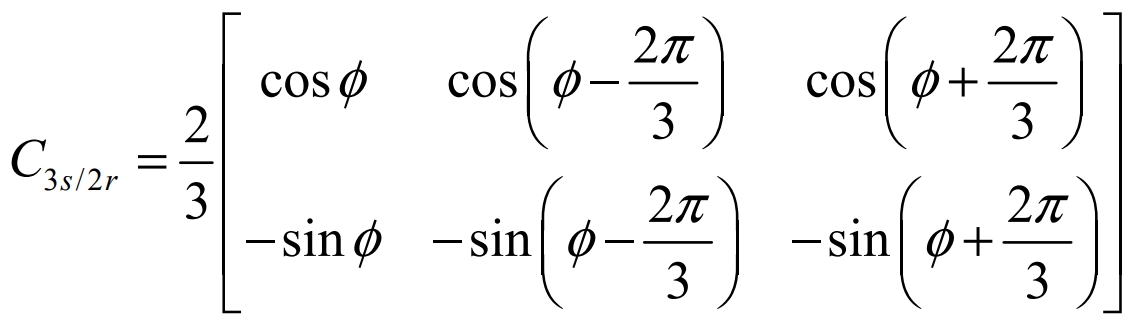
The transformation matrix for 3s/2r is:
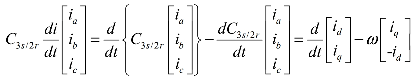
Perform a 3s/2r coordinate transformation on the formula:
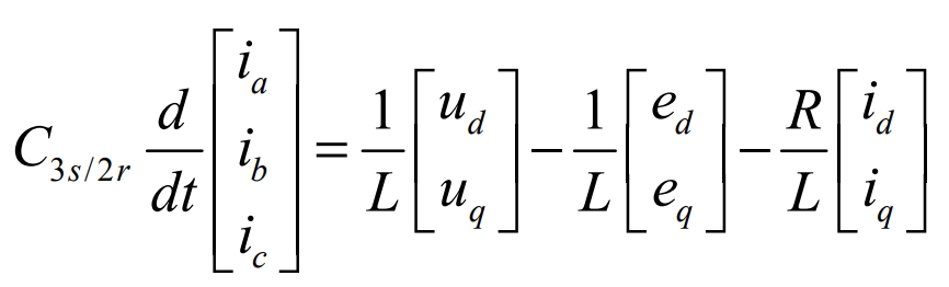
After transformation:
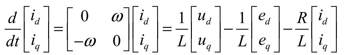
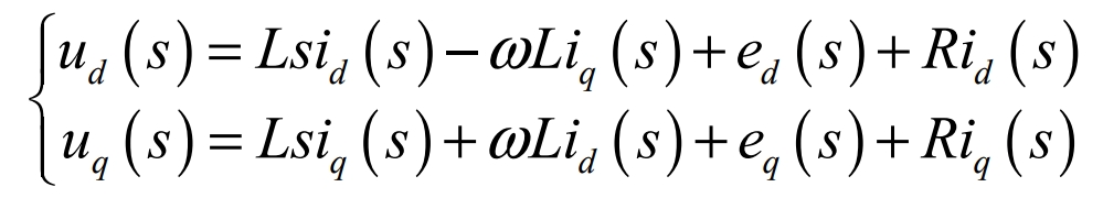
After coordinate transformation, the mathematical model of the photovoltaic grid-connected three-phase inverter in the (d, q) coordinate system is:
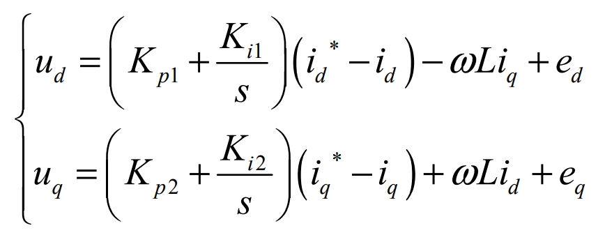
By rearranging the above formula, the output voltage of the photovoltaic grid-connected three-phase inverter can be obtained:
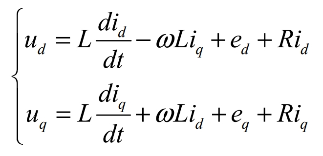
From the above formula, it can be seen that the active power transmitted to the grid by the photovoltaic grid-connected system is adjusted according to the d-axis current, while the reactive power transmitted to the grid is adjusted according to the q-axis current.Therefore, the coordinate system in which the d-axis and q-axis current control vectors rotate synchronously with the grid voltage can achieve the decoupled control of the active power and reactive power of the photovoltaic grid-connected system to the grid.Because of the interconnection effect, the d-axis is defined to be consistent with the grid voltage vector, and the current component di in the d-axis direction is defined as the active current, and the current component qi in the q-axis direction is defined as the reactive current, so that iq = 0 and eq = 0.
3. Control of photovoltaic grid-connected control system
Photovoltaic grid-connected inverters are voltage source current source inverters, which generally use dual-loop control: current inner loop and voltage outer loop. In order to achieve synchronization with the power grid, a phase-locked loop is also required.
3.1 Current inner loop
As can be seen from the formula, the mathematical model of a three-phase photovoltaic grid-connected inverter is a strongly coupled system, indicating that the tracking effect of the d-axis and q-axis current commands is not very satisfactory, and it is affected by the coupling voltage -ωLiq and ωLid as well as the grid voltage de and qe.Therefore, when using current closed-loop control, it is necessary to decouple the d-axis and q-axis currents, because the d-axis and q-axis currents are affected by the control variables du and uq, otherwise the design difficulty of the photovoltaic grid-connected control system will be greatly increased.Here, current feedforward decoupling control is used to remove the coupling effect of the d-axis and q-axis currents.
The Laplace transform of the formula is:
1). Control algorithm for active current di:
Transformed:

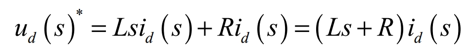
In order to cancel the effects of ωLiq(s) and ed(s), -ωLiq(s) and +ed(s) need to be added to the control algorithm.At steady state, we have:

In the control algorithm, in order to reduce unnecessary trouble, a PI regulator should be used for control, and the following formula is obtained through conversion:
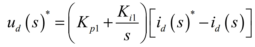
Here, us(s)* is the voltage setpoint of ud(s), id(s)* is the current setpoint of id(s), Kp1 is the proportional adjustment gain, and Ki1 is the integral adjustment gain.
2). Control algorithm for reactive current iq(s)
Transformed:
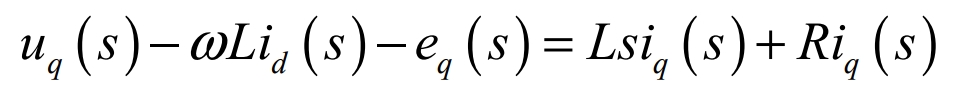
Try to avoid the impact caused by ωLiq(s) and ed(s).The control algorithm needs to include -ωLiq(s) and +ed(s).At steady state, it is:
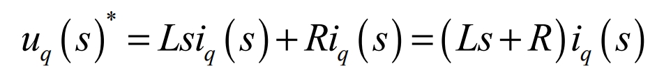
Similarly, in the control algorithm, in order to reduce unnecessary trouble, a PI regulator should be used for control, and the following formula can be obtained through conversion:
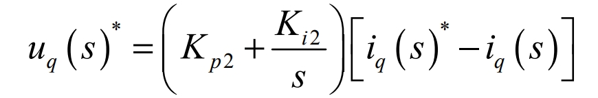
Here, uq(s)* is the voltage setpoint of uq(s), iq(s)* is the current setpoint of iq(s), Kp2 is the proportional adjustment gain, and Ki2 is the integral adjustment gain.
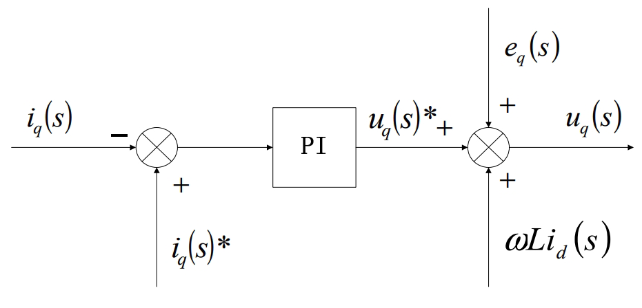
Therefore, the current feedforward decoupling control algorithm can be obtained through the control algorithm of the active current di and reactive current iq(s) described above:
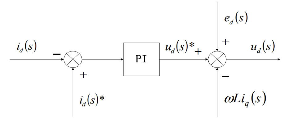
The corresponding control algorithm block diagram:
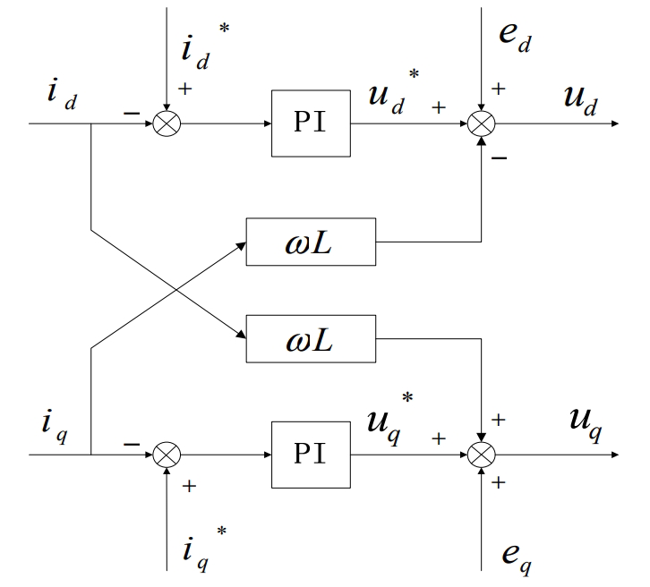
Substitute the formula:
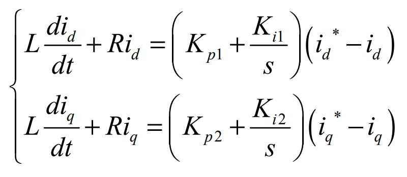
By calculating the above formula, it can be seen that the current feedforward decoupling control algorithm enables the control of currents di and qi to be independent of each other, thus achieving decoupling control of the current loop. It can also control the decoupling of the active and reactive power of the three-phase photovoltaic inverter, providing more effective control of the grid-connected grid current.
3).Parameter selection of PI regulator
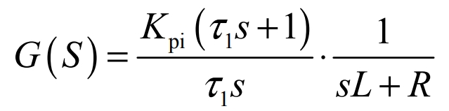
The PI regulator transfer function is:
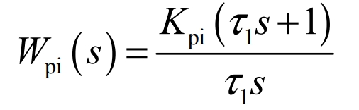
We simplify the current loop transfer function using the above formula, and obtain the PI parameter design block diagram for the current inner loop:
Thus, the open-loop transfer function of the current loop is obtained:
Adding the sampling step 1/Ts s +1, we can transform to:
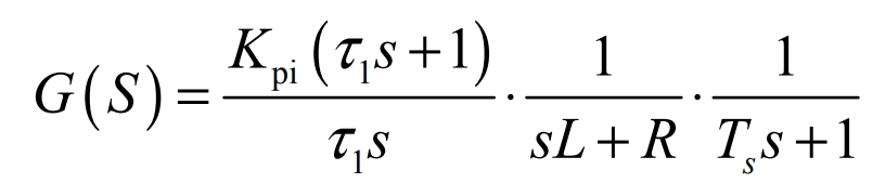
After transformation, the formula becomes:
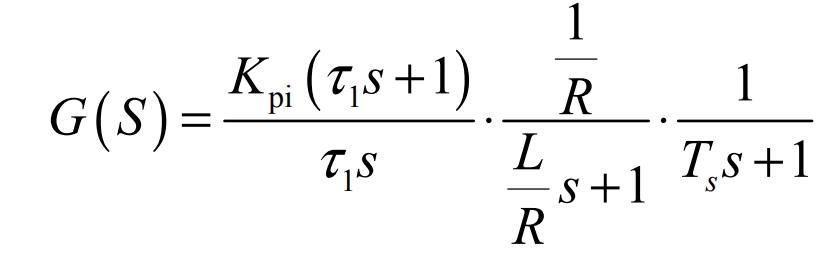
The simplified open-loop transfer function is obtained:
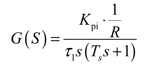
Transform the open-loop transfer function of the system into the following time constant form:
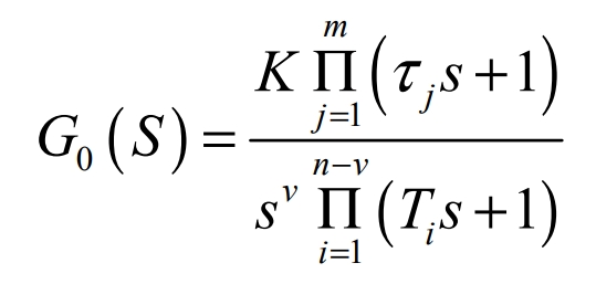
In the formula, v is the number of system types, v = 0 is called a zero-type system, v = 1 is called a type I system, and v = 2 is called a type II system;K is the open-loop gain.
Transforming the formula into a formula form yields:
Comparing the formulas, we can obtain v = 1, indicating that the system is a type I system;τ j = 0;Ti = Ts;
Because the open-loop gain of the current loop requires an overshoot of σ i ≤ 5%, KT∑ i = 0.5 should be taken, where T∑i is the sum of the small time constants of the current loop. Here, 4 1 10− T∑i = Ts = × , then:
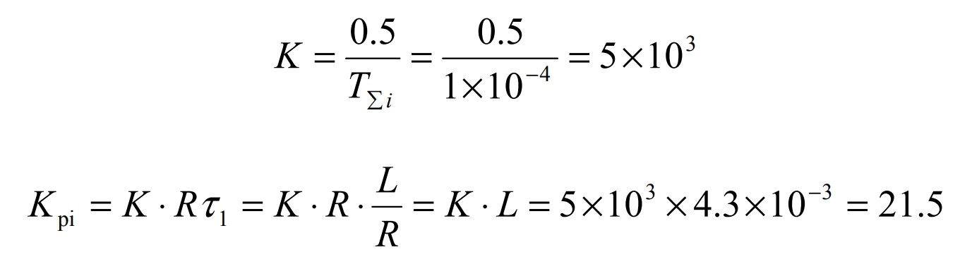
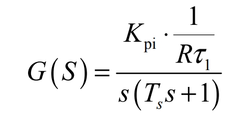
According to the above calculation, the transfer function of the PI regulator can be obtained as:
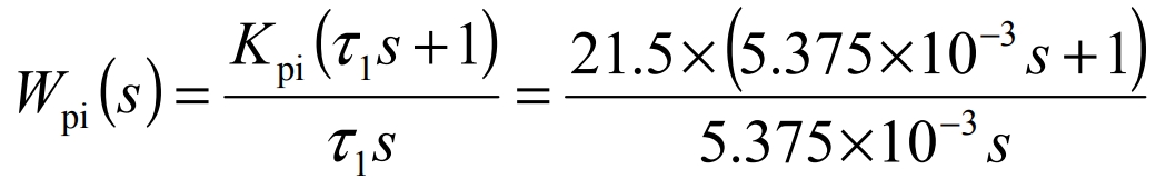
Transform the formula into the following form:
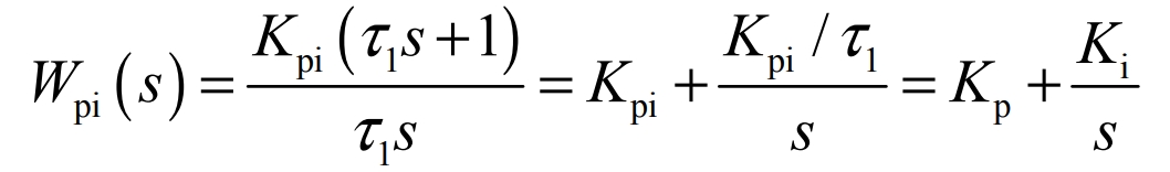
Where, Kp is the proportional parameter of the PI regulator;Ki is the integral parameter of the PI regulator.Through the above calculation, we can obtain:
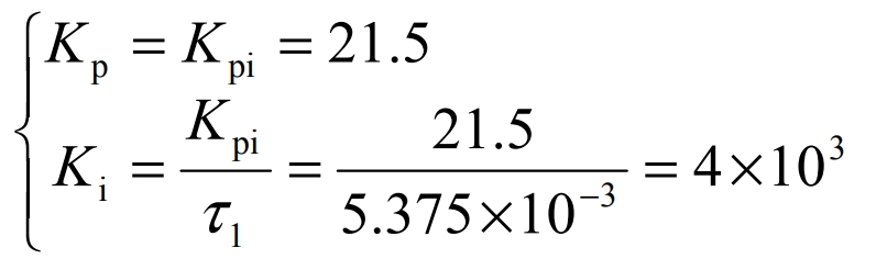
The Kp and Ki in the above formula have corresponding adjustable ranges. In practice, to ensure the stability of the system, it is necessary to adjust repeatedly, so that the appropriate values of Kp and Ki can be found.
3.2 Voltage outer ring
In a photovoltaic grid-connected system, stable control of the DC bus capacitor voltage is a prerequisite for the stability of the photovoltaic power generation system.Therefore, in order to ensure stable operation of the system, it is necessary to implement a capacitor voltage outer loop control for the DC bus voltage.
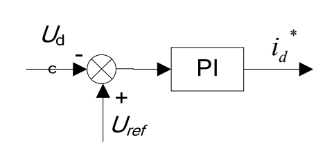
As shown in Figure 9, the voltage loop control can collect the parameter DC bus voltage Udc. The DC bus voltage control is achieved by subtracting the collected DC bus voltage Udc from the given voltage command Uref. At the same time, the DC bus PI controller adjusts the error input and outputs the d-axis active reference current *di to ensure the stability of the DC bus voltage.The transfer function of the voltage outer loop PI regulator is:
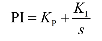
KP is the proportional parameter of the PI regulator;KI is the integral parameter of the PI regulator.KP and KI can be obtained through experience and repeated debugging.
3.3 Phase-locked loop
The design of grid-connected inverters requires phase-locked loops to obtain phase information of the grid voltage, which can achieve unity power factor operation of the grid-connected inverter system through the phase information of the grid voltage.During the entire design process, even if other aspects are perfect, the importance of phase-locked loops cannot be reduced, and the performance of phase-locked loops determines the performance of the grid-connected control system to a certain extent.The prerequisite for ensuring good dynamic performance and stability of the grid-connected control system is that the phase-locked loop can accurately and quickly detect the phase and frequency of the positive-sequence voltage component in the grid voltage under non-ideal grid voltage conditions.
The phase-locked loop circuit is a closed-loop regulation system composed of a phase detector, a loop filter, and a voltage-controlled oscillator.
The phase detector compares the instantaneous phase θ of the three-phase input voltage with the output phase θ0, and outputs a phase error signal△θ.The loop filter low-pass filters the phase error signal to remove high-frequency interference and noise, and outputs frequency control.Accumulate the digital control oscillator frequency control word, and output the tracking phase θ0When the error between the output phase θ0 and the instantaneous phase θ of the three-phase input voltage is zero, the loop filter outputs a stable frequency control word, and the angular frequency of the digitally controlled oscillator is constant, achieving frequency tracking and phase locking.The output phase θ0 is the instantaneous phase of the three-phase input voltage.
Set the angular velocity ω of the voltage space vector V rotating counterclockwise.If ω=ω0, the voltage space vector V and the dq coordinate system remain synchronized. Then the d-axis and q-axis components of the voltage vector V in the dq coordinate system are a constant value.After conversion, it is:
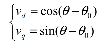
When θ is very close to θ0, sin(θ-θ0)= (θ-θ0), we replace the phase difference with the q-axis component of the dq coordinate system, which uses Clark transformation and park transformation to achieve the instantaneous phase of the three-phase input voltage.
The loop filter of the three-phase phase-locked loop is controlled using a PI regulator, and its transfer function is:
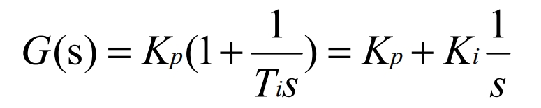
Where Kp is the proportional coefficient of the PI regulator, Ki is the integral coefficient of the PI regulator, and the relationship between its input deviation and output control signal is:
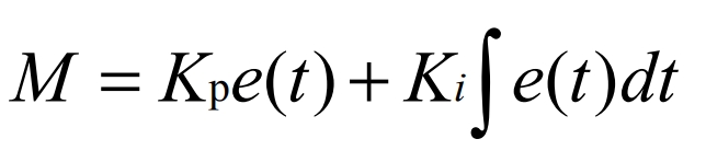
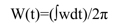
The control principle of the three-phase phase-locked loop is: a numerically controlled oscillator that accumulates the output frequency of the loop filter. When the accumulated value reaches 2π, the system resets, and this process is repeated to track the angular frequency of the sine wave.We can express this using the following formula:
4. Simulation research on photovoltaic grid-connected control system
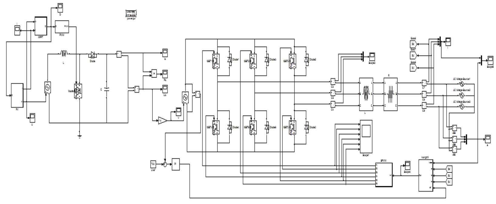
Through the above analysis, we use MATLAB to simulate the model, as shown in the figure below:
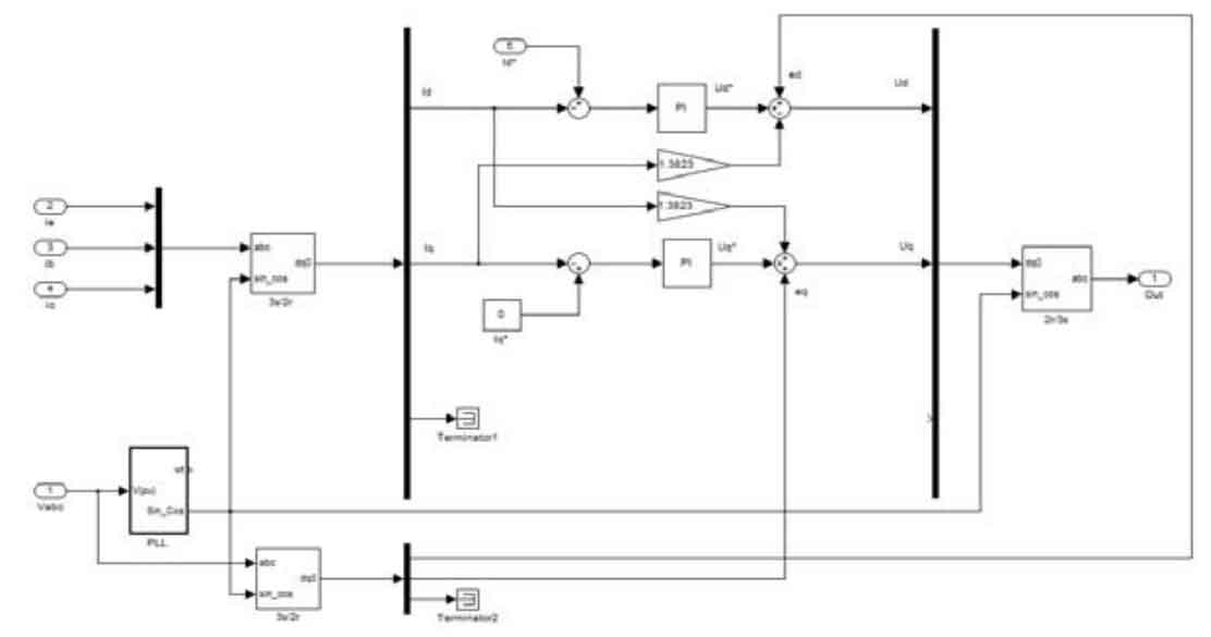
Figure 11 shows the main circuit simulation model of a three-phase photovoltaic grid-connected inverter. The main circuit consists of a three-phase full-bridge inverter, a photovoltaic cell model, a grid inductor, a grid power supply, and a boost circuit.The inverter control circuit, the boost circuit, and the MPPT circuit are the main components of the control circuit.
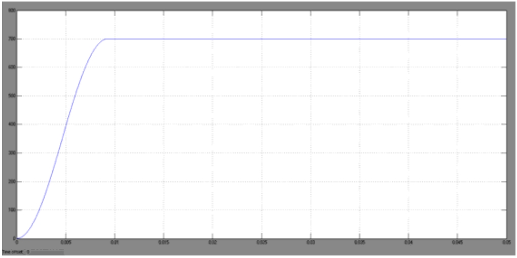
As shown in Figure 14, the output voltage of the DC bus is controlled at 700V, which proves that the voltage outer loop design is correct.
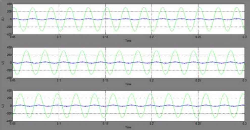
As shown in Figure 15, if the current loop of the photovoltaic grid-connected inverter is controlled correctly, the power factor of the three-phase photovoltaic grid-connected inverter is 1, and the three-phase grid-connected output currents A, B, and C should have the same frequency and phase as the three-phase grid voltage.
5. Summary
Firstly, the working principle of the photovoltaic grid-connected control system is introduced. The three-phase photovoltaic grid-connected control system is designed through the research of the three-phase voltage-source bridge inverter circuit, and the parameters of the three-phase photovoltaic grid-connected control system are calculated and analyzed. The simulation parameters of the filtering inductance are calculated.Then, a mathematical model of the three-phase photovoltaic grid-connected inverter is established, and a dual-loop control method with voltage outer loop and current inner loop is selected to control the photovoltaic grid-connected control system. A simulation model is constructed to verify the correctness of the control strategy.