
Isolated solar grid connected inverters use transformers for electrical isolation, which are large in size, high in cost, low in efficiency and power density. Non isolated solar inverters without transformers have small size, light weight, and low in cost and efficiency. However, the leakage current problem not only leads to safety hazards, but also seriously restricts their development. According to VDEO126-1-1 standard, the amplitude of leakage current in photovoltaic systems must be less than 300 mA21. In recent years, scholars from various countries have conducted extensive research on the issue of leakage current, and based on the research mechanism and establishment of models, many practical and feasible solutions have been proposed. Propose ways to change the topology structure and control strategy to solve the leakage current problem. Use a half bridge topology to connect the neutral point of the power grid to the midpoint of the DC side voltage divider capacitor. It suppresses leakage current but increases system losses, resulting in low DC voltage utilization. Reference [5] proposes a two-level common ground topology, but its output voltage contains significant harmonic components. Reference [6] proposes a multi-level common ground topology, but its control method is complex. At present, research on common ground topology is only applied to single-phase systems. For commonly used three-phase systems, there is no suitable topology structure that can completely eliminate leakage current.
In response to the above shortcomings, a combined three-phase non isolated solar inverter topology with flying capacitors is proposed. This topology connects the negative end of the photovoltaic panel to the ground wire, which can maintain the total common mode voltage unchanged and completely eliminate leakage current. The three-phase decoupling operation of solar inverters has strong ability to carry asymmetric loads.
1.Combined three-phase solar inverter with flying capacitor
1.1 Topology
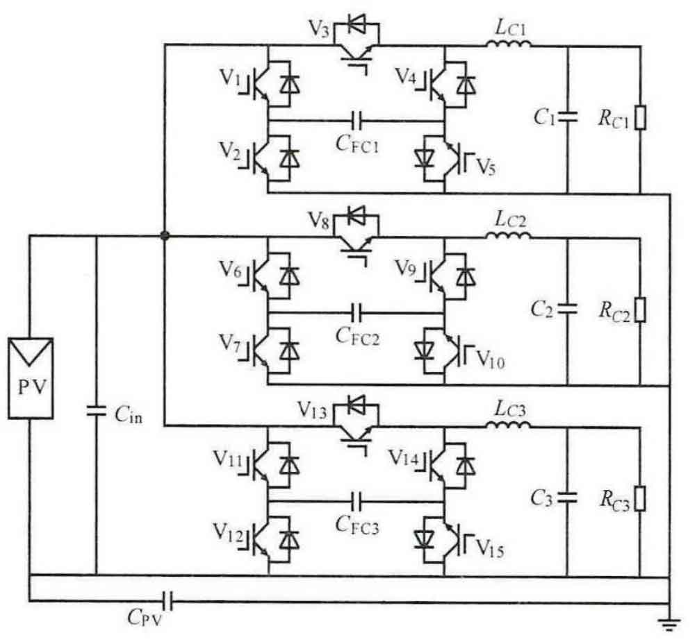
The circuit principle of a combined three-phase solar inverter with flying capacitor is proposed here, as shown in Figure 1. U represents the DC input voltage and CP represents the parasitic capacitance of the photovoltaic panel to the ground; C is the DC side voltage stabilizing capacitor; Gc, Grcz, C are flying capacitors; C. C and G are filtering capacitors; La, L, Le are the filtering inductors; V. ~Vs is the switch tube. This topology structure can divide the system into three single-phase circuits with independent solutions, and each phase operates independently of each other.
1.2 Common Mode Model Analysis of Combined Three Phase Solar Inverter
From the previous section, it can be seen that the solar inverter is composed of three independent single-phase H5 solar inverters. Therefore, for the common mode analysis of the three-phase solar inverter, it can be decomposed into the analysis of a single-phase common mode model.
The common mode equivalent model of a single-phase non isolated solar inverter is shown in Figure 2. Among them, PV refers to photovoltaic panels; PN represents the positive and negative terminals of the photovoltaic panel, C represents the DC stabilized capacitor, and L represents the filtering inductance; C is the parasitic capacitance to the ground.
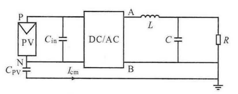
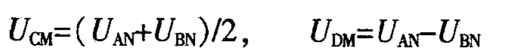
From Figure 2, it can be seen that the common mode voltage and differential mode voltage are:
By simplifying the common mode equivalent model shown in Figure 2, the simplest model can be obtained as shown in Figure 3.
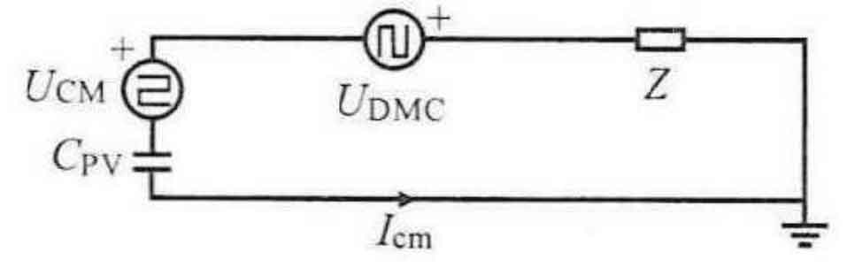
Define its total common mode voltage as:
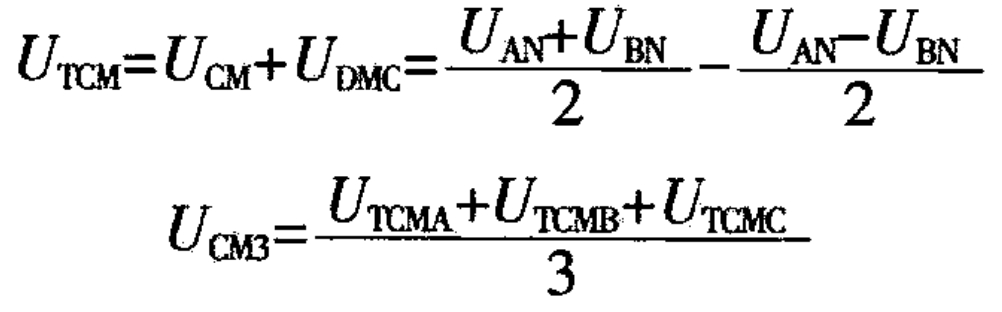
In the formula: Urou, Urw, Uaw are the total mode voltages of A, B, and C phases, respectively; Uow is the total equivalent differential mode voltage; U is the total mode voltage of the three phases.
For a combined three-phase solar inverter, the total leakage current is the sum of the leakage currents of each phase, as shown in equation (3). To make the total leakage current zero, it is necessary to maintain the total mode voltage unchanged.
1.3 Working principle and leakage current suppression
The combined three-phase solar inverter topology consists of three independent single-phase solar inverters, so its operating mode can also be analyzed independently. Taking phase A as an example, the specific working modes of phase B and phase C are similar to phase A but have phase differences.
The specific work includes 8 modes as shown in Table 1.
| Modal | V1 | V2 | V3 | V4 | V5 |
| 1 | 1 | 0 | 1 | 0 | 1 |
| 2 | 1 | 0 | 0 | 0 | 1 |
| 3 | 0 | 1 | 0 | 1 | 0 |
| 4 | 0 | 0 | 0 | 1 | 1 |
| 5 | 0 | 1 | 0 | 1 | 0 |
| 6 | 1 | 0 | 0 | 1 | 1 |
| 7 | 1 | 0 | 1 | 1 | 1 |
| 8 | 1 | 0 | 0 | 0 | 1 |
The specific analysis of the 8 modes is as follows:
Mode 1 switch V;, V; V. In a conducting state, while other switch tubes are in a off state; The power supply supplies power to the load while charging the flying capacitor.
Modal 2 V, V; In a conductive state, while other switch tubes are in a off state, the power supply continues to charge the flying capacitor, while the inductance
Lc discharge continuation. Mode 3 VV. In the on state, the other switch tubes are in the off state. Current flows out of the inductor and continues to fly across the capacitor charging mode 4 V. V. in the on state, while the other switch tubes are in the off state. The inductor continues to flow.
Mode 5 VV is in a conduction state, while other switch tubes are in a off state to provide energy for flying capacitor discharge and supply power to the load.
Mode 6 V.V.V. is in a conduction state, while other switch tubes are in a off state. The power supply is for flying capacitor charging, while L discharge continues.
Modal 7 V, V;, V is in a conductive state, while other switches are in a off state. The power supply and inductance current together charge the flying capacitor.
Modal 8 ViV, V. The other switch tubes are in a conduction state, and the power supply continues to charge the flying capacitor while the inductance continues to flow.
Taking phase A as an example, mode 1 operates normally.

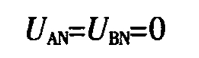
According to the formula, the total common mode voltage of phase A can be obtained as:
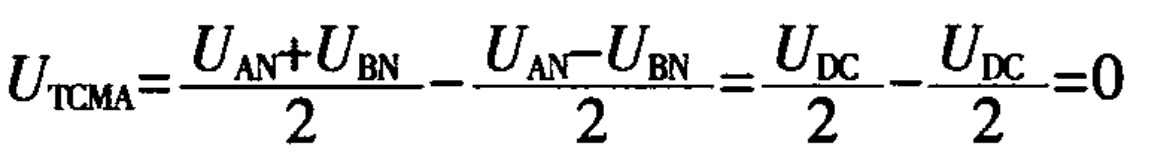
In modes 3 and 2,4, it can be seen that the common mode voltage in this mode is:
The analysis results for phase B and phase C are similar and will not be repeated here. The total mode voltage of the three-phase solar inverter is:
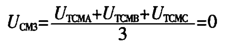
From the above analysis, it can be seen that the total mode voltage of each phase in the combined topology remains unchanged, and the common mode voltage of the entire system can remain unchanged. This combined topology has the ability to completely eliminate leakage current. two point four
1.4 Combined variable control scheme
Unipolar SPWM has smaller switching and filtering inductance losses compared to bipolar SPWM, making it more efficient. To meet the leakage current regulations and standard requirements issued in China in 2013, a synchronous dual carrier unipolar SPWM method is adopted as shown in Figure 4.
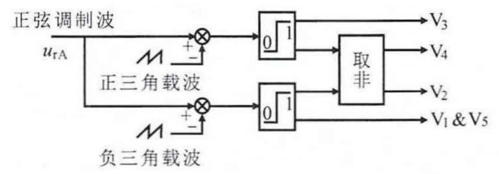
Two carrier sequences have different DC biases. The harmonics at the carrier can cancel each other out and improve the waveform. In addition, this method can conveniently perform continuous duty cycle changes, effectively allowing the system to smoothly switch between different output voltages, which has reference significance for the continuous improvement of the system. The entire system adopts a single voltage closed-loop control based on sine pulse width control, which can ensure the stability of the output voltage during input voltage fluctuations and load changes.
1.5 Design principles for flying capacitors
The flying capacitor is charged by the photovoltaic cell in the positive half cycle and provides energy in the negative half cycle of operation, so the selection of the flying capacitor is very important for this topology.
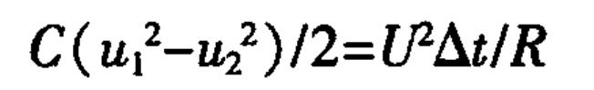
When discharging a negative half cycle capacitor, the energy released by the capacitor is approximately equal to the energy consumed by the load, and a mathematical model is established:
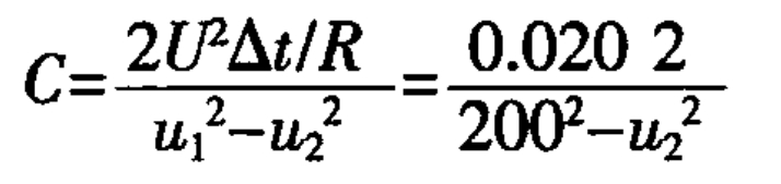
In the formula: U=110 V; R=60; T=0.5/f/=20 kHz; U=200 V.
By substituting the parameters, we can obtain:
In addition, to ensure that the voltage ripple of the capacitor is relatively small, it is required that the voltage fluctuation does not exceed 5 V:
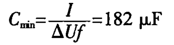
In the equation; I=1.82 A. According to equations (8) and (9), the larger the capacitance, the smaller the voltage change, but it will increase the cost. The smaller the capacitance, the lower the cost, but the larger the voltage change, the greater the discharge current and ESR loss. After comprehensive consideration, if u=199.9 V is selected, with only a 0.1V variation and little impact on the output voltage, then C=252 uF is selected as a 220 mF/400V capacitor. In addition, considering that the flying capacitor is a key factor affecting the normal operation of the circuit, it is chosen to parallelize two 220 uF capacitors as flying capacitors to ensure the normal operation of the circuit.
2. Experimental verification
A prototype of the experimental principle was built, with the following experimental parameters: an input voltage of 200 V; The output voltage of each phase is 110 V; Single phase rated power is 200W; The output frequency is 50H, the switching frequency is 20 kHz, and the DC bus capacitance is 22 uF; Filter capacitor head 4.7uF; The filtering inductance is 5mH; The flying capacitance is 440uF, and the parasitic capacitance to ground is 100 pF.
Figure 5 shows the main experimental waveforms at full load.
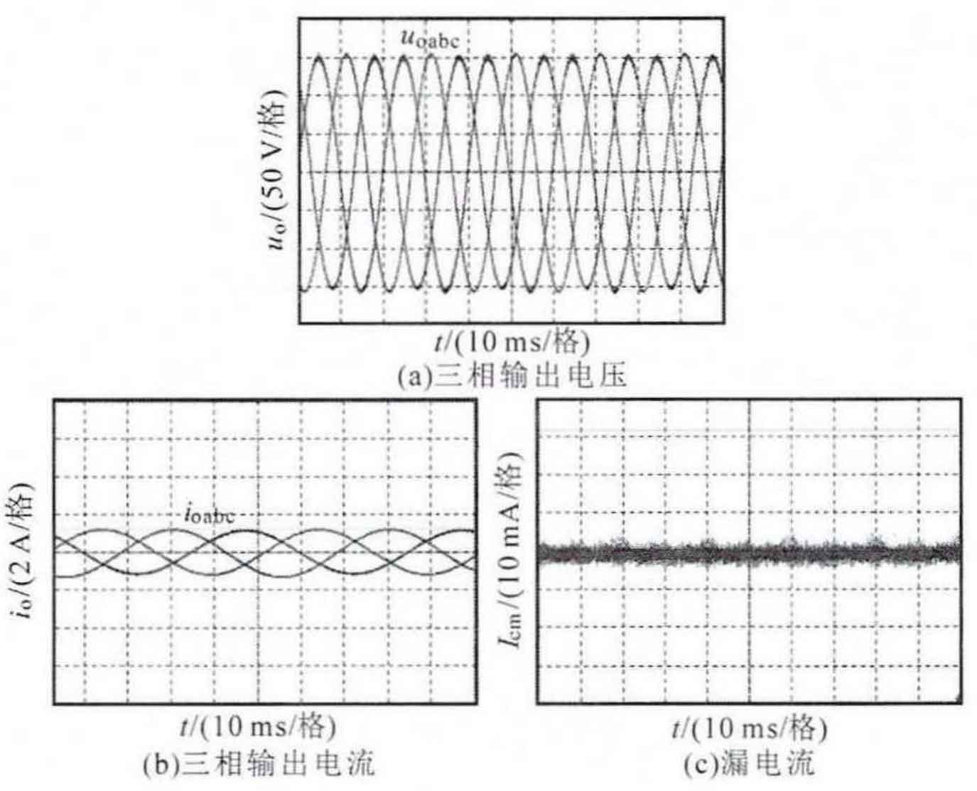
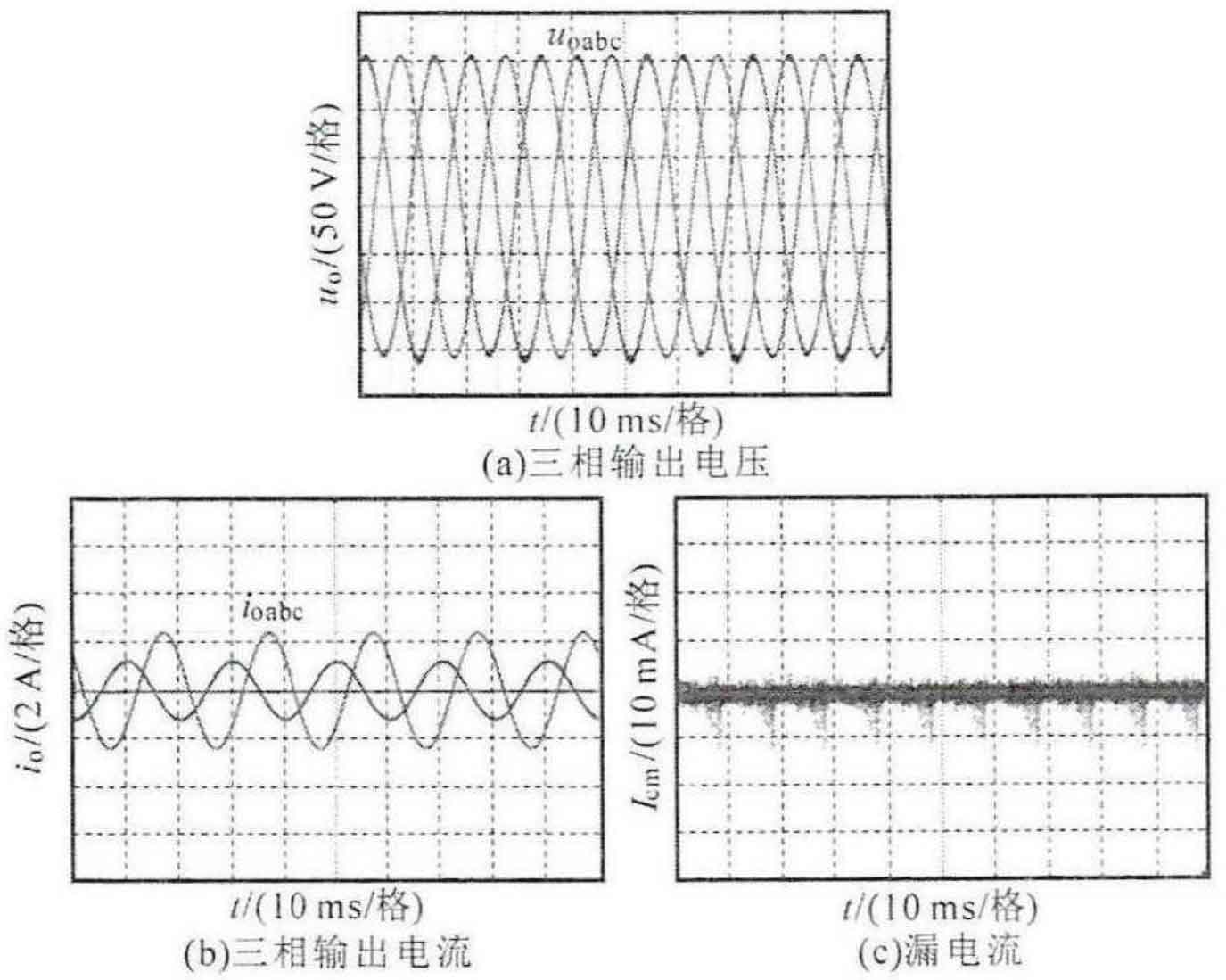
Figure 6 shows the main experimental waveforms with unbalanced loads. From this, it can be seen that the output waveform of the solar inverter is of high quality, and due to the short-circuit of the parasitic capacitance to the ground of the photovoltaic panel, the peak current under full load conditions is about 9mA; The peak leakage current under asymmetric negative conditions is approximately 8mA.
3. Conclusion
A combined three-phase leakage current free solar inverter with flying capacitor is proposed here. Compared with existing solar inverters, this topology has the advantages of completely eliminating leakage current and having strong asymmetric load capacity. The modulation strategy is simple and easy to implement. Analyzed the working principle, mode, control strategy, and parameter selection of the solar inverter, and finally built an experimental prototype to verify the feasibility of the three-phase topology. The idea of using short-circuit photovoltaic panels with parasitic capacitance to the ground can provide reference for other non isolated solar inverters.