
Under the background of “dual carbon”, China vigorously promotes the development of new energy. With the maturity of photovoltaic power generation technology, the position of solar energy in new energy is becoming increasingly important. In recent years, large-scale solar photovoltaic grid connection has brought great challenges to the power grid. The harmonics generated during the grid connection process seriously damage the power quality of the input grid, greatly reducing the efficiency of photovoltaic power generation grid connection. The harmonic control in the power grid mostly adopts passive control, using active filters to suppress harmonics in the system. Due to the similarity in topology between photovoltaic inverters and active filters, the integration of photovoltaic inverters and active filters for unified and coordinated control can greatly improve the effectiveness of harmonic control and improve the quality of power grid harmonics from the source.
Accurate and effective tracking and control compensation of harmonics are key in harmonic control, among which the ip-iq harmonic detection method based on instantaneous reactive power theory has been widely applied. Many scholars have conducted research on harmonic current control strategies: the deadbeat control strategy is adopted in the synchronous rotating coordinate system. Although the control principle is simple and the response speed is particularly fast, this control strategy requires high accuracy of the established mathematical model, complex calculation, and has certain limitations; The proportional integral (PI) control used in the system is easy to implement and has fast dynamic response, but it cannot perform zero static error tracking for the AC components in the system; The proposed Proportional Resonator (PR) control has poor anti-interference ability; Although repetitive control can reduce the static error of the system, it has the problem of periodic delay and poor dynamic response ability.
In order to solve the above problems, this article proposes to first use the ip-iq harmonic detection method based on instantaneous reactive power theory to accurately detect harmonics, and then combine the advantages of quasi PR control and repetitive control to form a composite control, which accurately and quickly compensates the harmonic current in the system, achieving unified and coordinated control of photovoltaic inverters and active filters. Finally, the effectiveness of this method was verified through simulation analysis.
1. Photovoltaic grid connected system
The photovoltaic grid connected system mainly includes modules such as photovoltaic cells, Maximum Power Point Tracking (MPPT) modules, photovoltaic inverters, and loads. The unified coordination and control diagram of the photovoltaic grid connected system is shown in Figure 1.
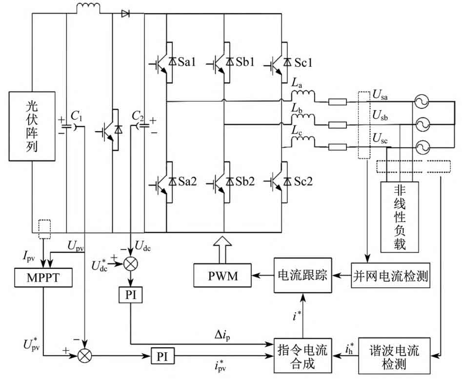
In Figure 1, Sa1, Sb1, Sc1, Sa2, Sb2, and Sc2 are the six internal topology switches of the three-phase grid connected inverter; C1 and C2 are buffer capacitors; Ipv and Upv are the output current and output voltage of the photovoltaic array, respectively, with U * pv being the maximum output voltage; Udc is the DC side voltage, and U * dc is the reference voltage; La, Lb, and Lc are three-phase filtering inductors; Usa, Usb, and Usc are three-phase grid connected voltages. The MPPT module first tracks the maximum power output of the photovoltaic array to maintain the maximum output power of the photovoltaic cell. The active current command i * pv and DC side voltage control command are obtained through PI control Δ The IP and load side harmonic current commands i * h are synthesized to obtain the current tracking command i *. Finally, quasi PR control and repetitive control are used to track the current, thereby controlling the output current of the photovoltaic inverter and compensating the grid current for harmonics.
2. Harmonic current detection
Harmonic current detection is a key link in photovoltaic grid connected systems, which detects the harmonic current of nonlinear loads and synthesizes harmonic current compensation signals through command currents to achieve harmonic compensation. Therefore, rapid and accurate detection of harmonic currents can greatly improve the efficiency and quality of harmonic compensation in the power grid.
At present, there are many methods for detecting harmonic currents. A harmonic detection method based on FBD (FryzeBuchholzDpenrock) method is proposed for detecting three-phase unbalanced power supply systems. An improved current average method is proposed to address the delay issue of low-pass filters in harmonic detection methods. An improved pq harmonic detection method based on instantaneous reactive power theory is proposed for three-phase voltage asymmetry systems. Among them, detection methods based on instantaneous reactive power theory have been widely applied due to their fast and effective characteristics, including pq method and ip-iq method. The principle of the ip-iq detection method based on instantaneous reactive power theory is shown in Figure 2.
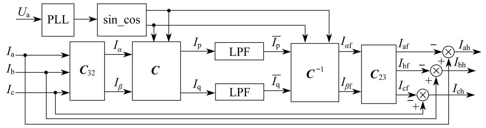
Figure 2, I α 、 I β For αβ Two phase instantaneous current in the coordinate system, I α f. I β F is αβ The fundamental current in the coordinate system, where Iaf, Ibf, Icf represent the three-phase fundamental current, Iah, Ibh, Ich represent the three-phase harmonic current, and LPF represents the low-pass filter.
Phase Locked Loop (PLL) performs phase locking on the input a-phase voltage Ua of the circuit, thereby extracting the signal sin cos that is in phase with Ua, and adding the extracted phase signal sin cos to the harmonic detection circuit. The formulas for three-phase voltage and three-phase current are:
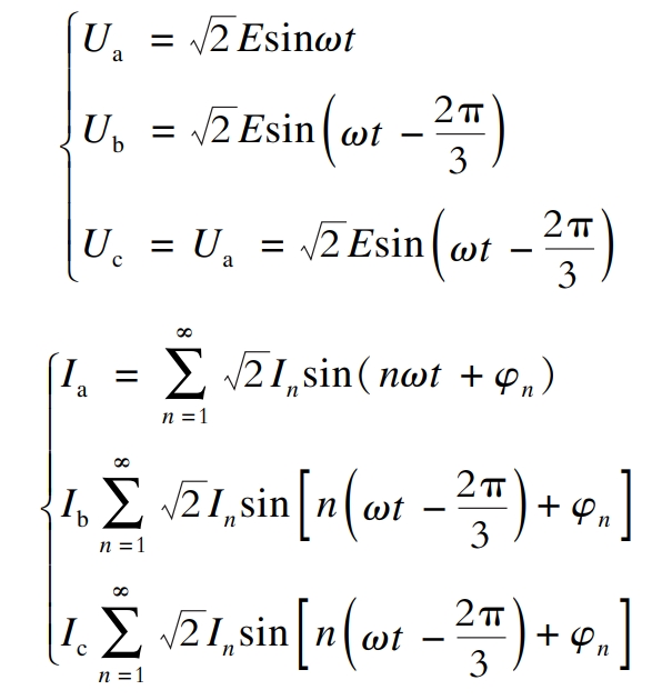
In the formula: Ua, Ub, Uc – voltage of phase a, phase b, and phase c;
E – effective voltage value;
ω——— Angular frequency;
Ia, Ib, Ic – phase a, phase b, and phase c currents;
In φ N – effective value of n times of current and n times of phase;
T – Time.
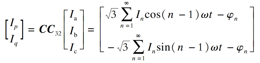
Ia, Ib, and Ic are converted to obtain the Ip and Iq components.
The transformation matrix is:
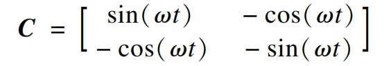
The coordinate conversion matrix is:
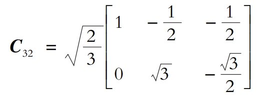
The coordinate inverse transformation matrix is:
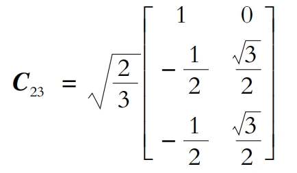
Firstly, the instantaneous active current Ip and instantaneous reactive current Iq are obtained through CC32 transformation. Ip and Iq are filtered by a low-pass filter to obtain the DC component of the current. Then, the fundamental signals Iaf, Ibf, and Icf are obtained through C-1C23 transformation. Finally, the harmonic current is obtained by subtracting the fundamental current from the three-phase current.
3. Compound control
3.1 Quasi PR control
Quasi PR control is an improved control based on PR control, and the transfer function GPR of the controller is:
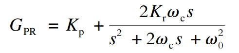
In the formula: Kp – proportional link coefficient;
Kr – resonance factor;
ω C – cutoff angle frequency;
S – Laplace operator;
ω 0- Resonance angle frequency.
Different Kr, Kp ω The bode diagram of C-time quasi PR control is shown in Figure 3.
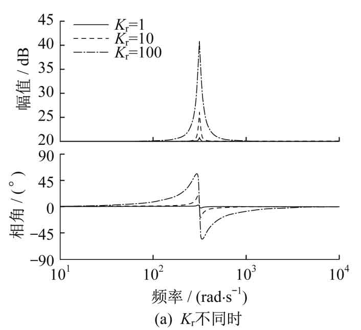
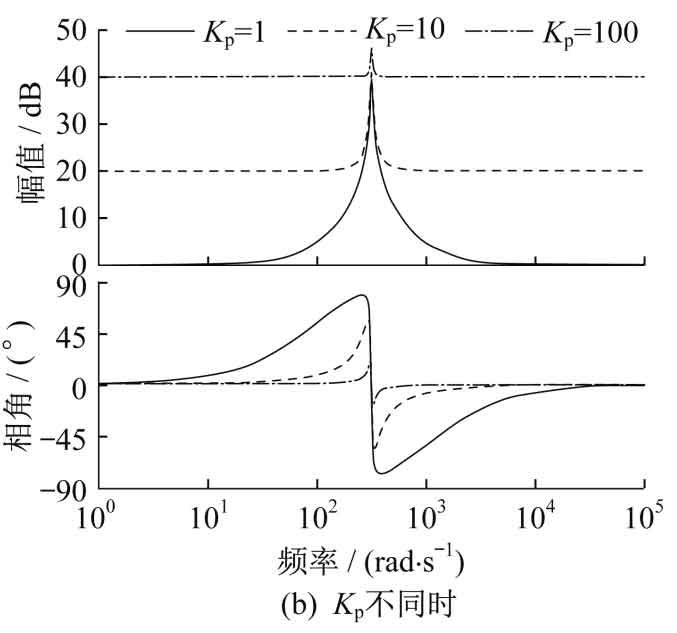
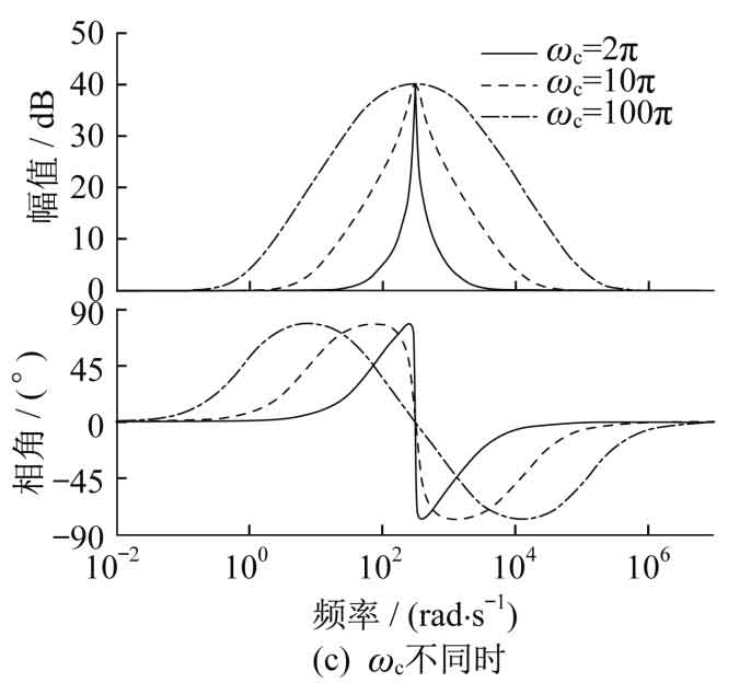
In Figure 3 (a), the gain of the system at the fundamental frequency increases as Kr increases. From Figure 3 (b), it can be seen that as Kp changes, the peak value at the fundamental frequency remains basically unchanged, while the amplitude outside the resonant bandwidth changes. The overall curve moves upwards with the increase of Kp. In Figure 3 (c), ω When c increases, the gain of the system at the fundamental frequency does not increase, but the bandwidth on both sides significantly increases.
Therefore, in order to ensure the stability of the system, it is necessary to align Kr, KP, and ω Take reasonable values for c. In this article, Kr=100 and Kp=10 are taken, ω C=5.
3.2 Traditional and improved repetitive control
The core idea of repetitive control technology is the principle of inner membrane, which involves implanting mathematical models of externally established action signals into the controller for application, in order to construct a high-precision feedback result control system. Improving the traditional repetitive control technology by replacing the delay link z-N in traditional repetitive control with Q (z) z-N in the inner membrane structure, and adding a compensator C (z) module to increase the stability margin of the system, resulting in better system stability. The block diagrams of two types of repetitive control structures are shown in Figure 4.
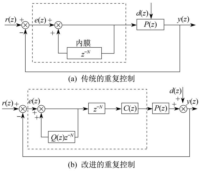
In Figure 4, r (z) and y (z) represent the input reference signal and output signal of the system, e (z) represents the error signal, the inner membrane structure is shown in the dashed box, d (z) represents the external periodic disturbance, and P (z) represents the control object of the system.
The compensator C (z) can compensate for the amplitude and phase fluctuations and deviations that occur in the system. The closed-loop transfer function of the system is:
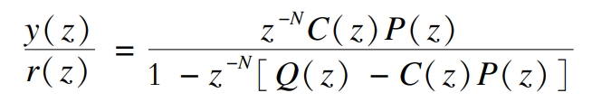
In the formula: Q (z) – attenuation module.
3.3 Composite control
Repetitive control technology can greatly reduce steady-state tracking errors in AC systems, and has good harmonic suppression effects. However, its dynamic response ability is poor, often resulting in a delay problem of one cycle.
Quasi PR control has good dynamic response ability, so the composite control combining quasi PR control and repetitive control can balance the advantages of both types of control, quickly and stably track the AC components in the system without static errors, and effectively suppress the harmonic components of the system. The block diagram of the composite control structure is shown in Figure 5.
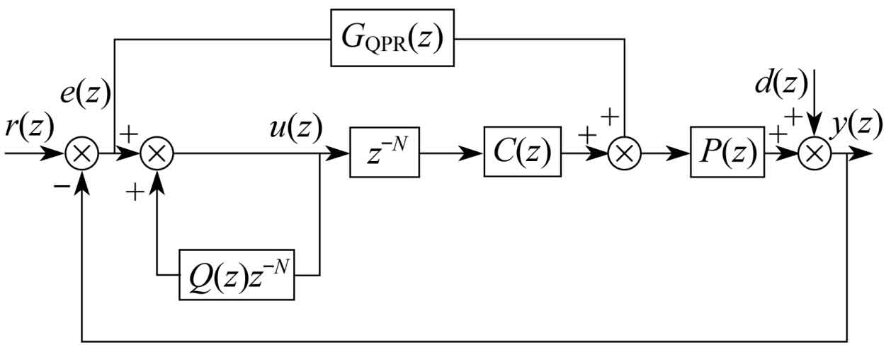
In Figure 5, GQPR is a quasi PR controller. In the composite control structure, the output of the quasi PR controller at the current time is combined with the error at the same time in the previous cycle as the output of the modulation signal control composite control, thereby reducing the error at the current time in each cycle and making it approximately zero. When the system is in a relatively stable state, repetitive control plays a major role in controlling the system output. When there is a significant disturbance in the system, due to the fast response ability of quasi PR control, the system is mainly controlled by quasi PR control. After a period of repeated control delay, the adjustment function is exerted to restore the system to a stable state.
3.4 Parameter design
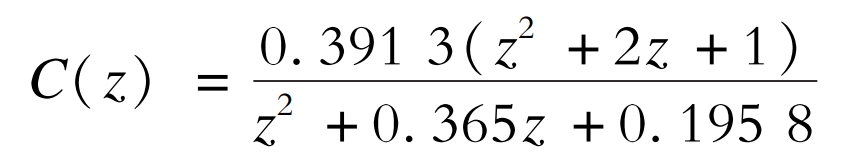
The compensator C (z)=KR · zk · S (z) is the most important link in the control system. KR is the gain coefficient, usually taken as 1; Zk is the leading link, taken as 2. The second-order low-pass filter S (z) is mainly used to eliminate high-frequency interference in the system and improve its stability. If the cutoff frequency of the filter is set too high, it will make the filtering effect of the filter meaningless and reduce system stability; If set too low, it will suppress the system’s output of high-frequency harmonics and reduce its compensation ability for high-frequency harmonics. Due to the fact that filters in practice mainly compensate for harmonics below the 25th order, it is required that the cut-off frequency of the filter should not be lower than the frequency of the 25th order harmonic.
If fc=2kHz, then filter C (z) is:
4. Simulation analysis
Use MATLAB/Simulink software for modeling and simulation. The main simulation parameters are as follows: the power supply is three-phase power grid 220V/50Hz; The switching frequency is 10kHz; On the DC side, Udc=600V, with a filtering inductance of 1.4mH and a buffer capacitance of 1mF; At the load end, the load resistance is 10 Ω and the load inductance is 3mH.
4.1 Simulation of harmonic detection module
The three-phase voltage of the system is symmetrical, and here phase a is taken for analysis. When nonlinear loads in the system generate harmonics and inject them into the power grid, active filters need to be filtered, so it is necessary to track and compensate for the harmonic currents in the power grid. Using the ip-iq harmonic detection method to detect the harmonics of phase A current Ia, the detected waveform of phase A current containing harmonics and its grid connected current harmonic distortion rate are shown in Figure 6.
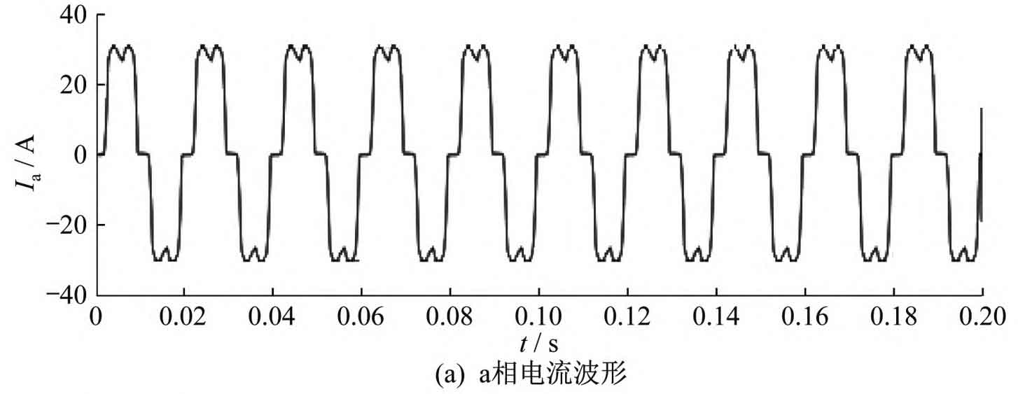
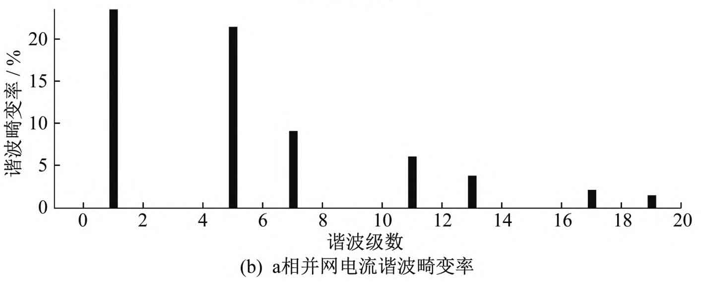
From Figure 6, it can be seen that the A-phase current does not exhibit a regular sine cosine waveform, which contains significant harmonic components. Through the analysis of the harmonic distortion rate using Fast Fourier Transform, it can be seen that the harmonic distortion rate in the detected A-phase current containing harmonics is 24.56%, with the 5th, 7th, 11th, 13th, 17th, and 19th harmonics having more harmonics.
4.2 Unified Coordinated Control Simulation
Traditional active filters have a good suppression effect on harmonics. Although the working principles of photovoltaic grid connected inverters and active filters are different, they have the same topology structure and similar control strategies. Therefore, the photovoltaic grid connected inverter and active filter are uniformly coordinated and controlled. When the light intensity is high on sunny days, the system obtains the final command compensation current signal through the command current tracking and synthesis module, and controls the photovoltaic inverter to generate a current that is the same or similar to the final command current to inject into the grid, improving the power quality of grid connected power.
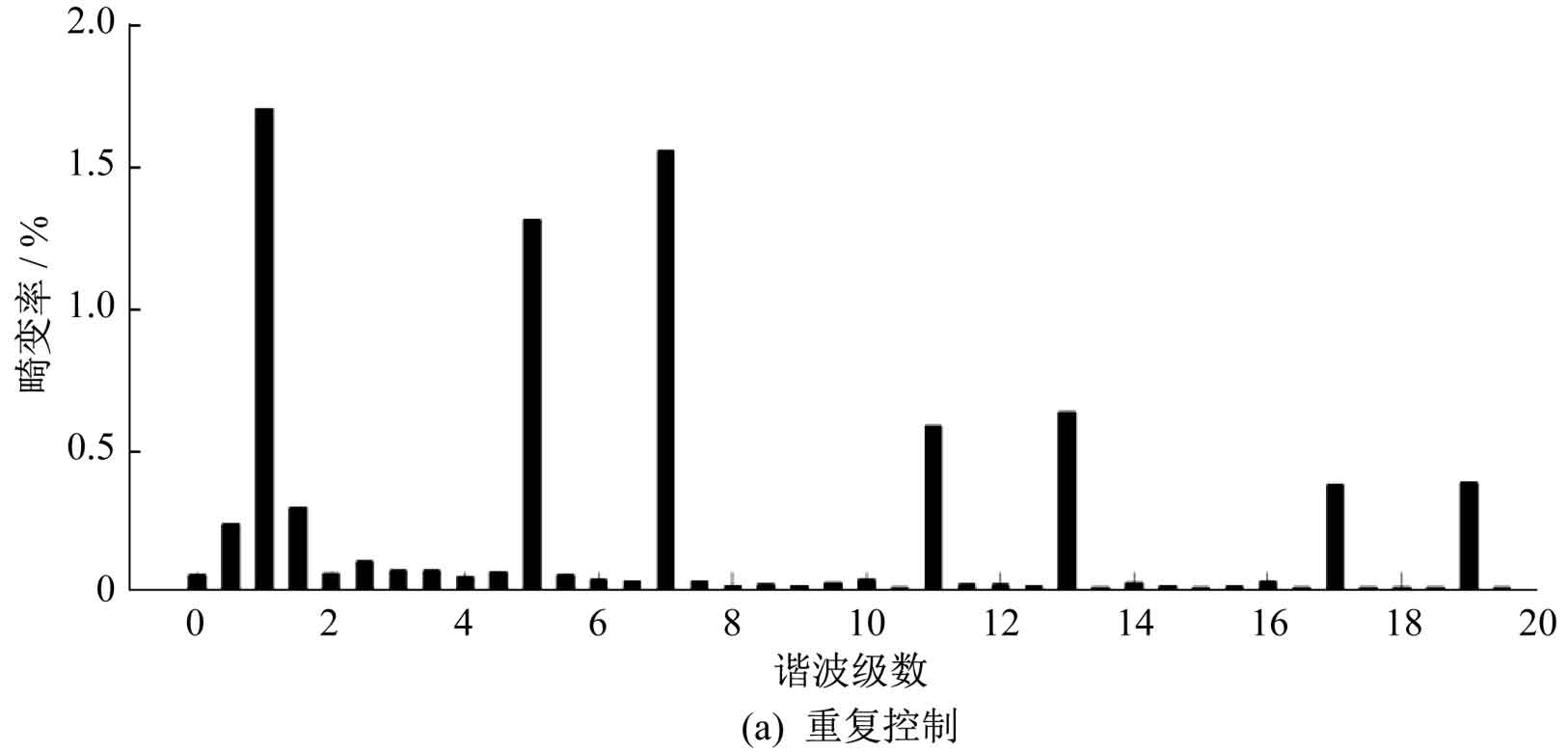
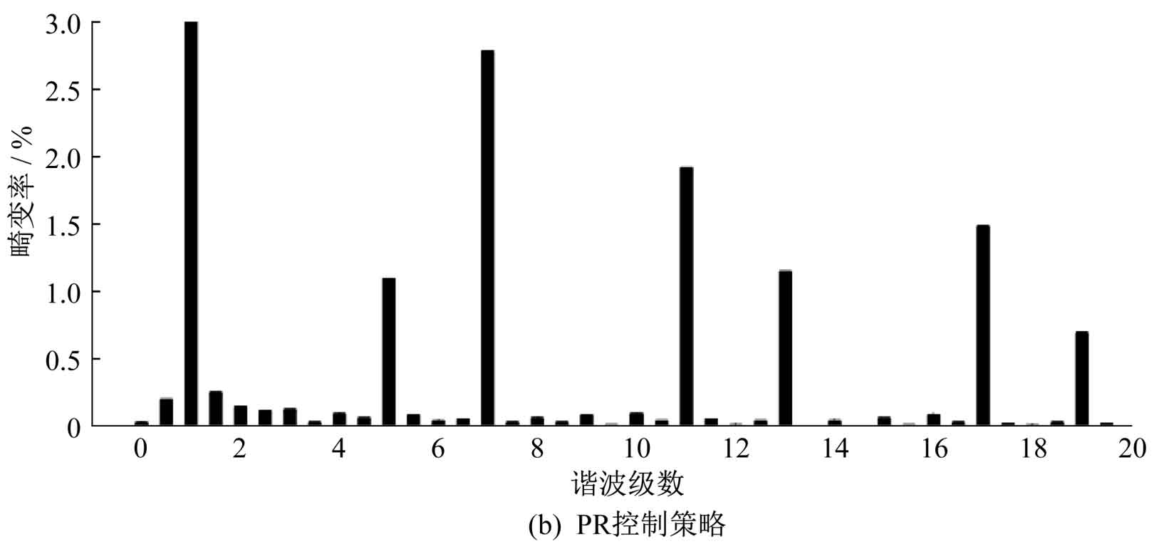
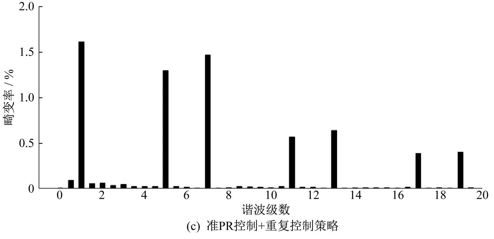
Under three control strategies of repetitive control, PR control, and quasi PR control+repetitive control, the simulation waveforms of grid voltage U and grid connected current I are shown in Figure 7. From Figure 7, it can be seen that under the repetitive control strategy, harmonics can be suppressed to a certain extent and the grid connected current waveform can be improved, but there is often a delay problem of one cycle and the dynamic response is relatively slow. Compared with repetitive control, PR control has better dynamic response ability, but the resulting current distortion is more severe. Quasi PR control+repetitive control can achieve zero static error tracking, fast dynamic response speed, and relatively small grid connected current distortion under control.
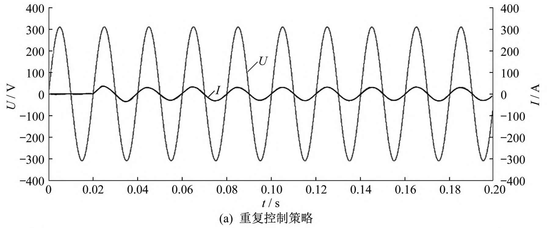
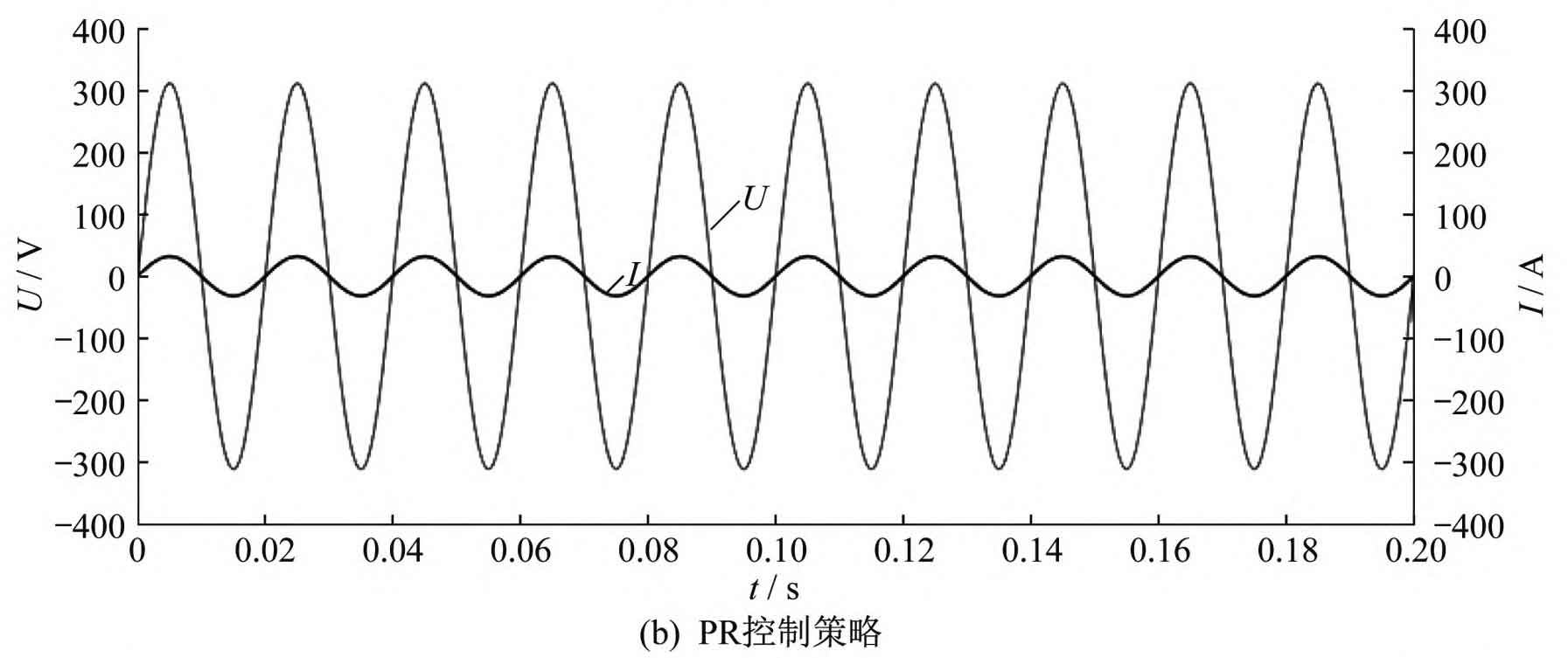
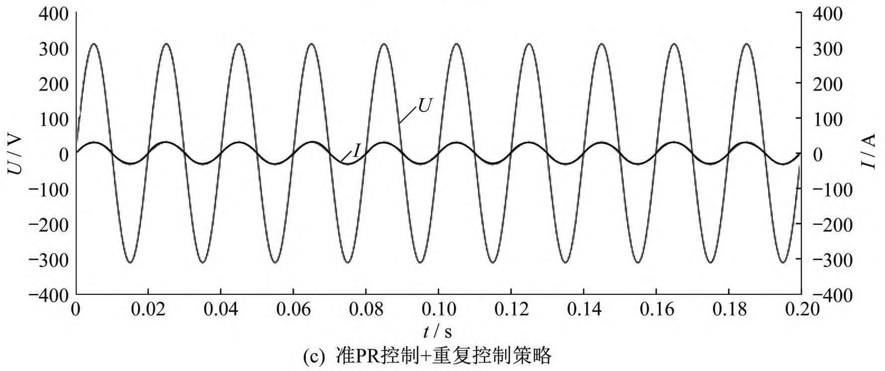
The harmonic distortion rate of grid connected current under three control strategies is shown in Figure 8. The calculation shows that under the repetitive control strategy, the total harmonic distortion rate of the current waveform is 2.32%, which has a certain inhibitory effect on harmonics; Under the PR control strategy, the total harmonic distortion rate of the current waveform is 4.65%; Under the quasi PR control+repetitive control strategy, the total harmonic distortion rate of the current waveform is 1.92%. Compared to using repetitive control and PR control alone, the harmonic content of the current waveform under composite control is significantly reduced, and the response speed and waveform quality are significantly improved.
Considering that in practical applications, the external weather and environmental temperature may change, the simulation conditions are changed as follows: the light intensity is increased to 1500W/m ^ 2, and the environmental temperature is increased to 30 ℃. After corresponding changes, the harmonic distortion rate of grid connected current, grid voltage, and grid connected current waveform under unified coordinated control are shown in Figure 9.
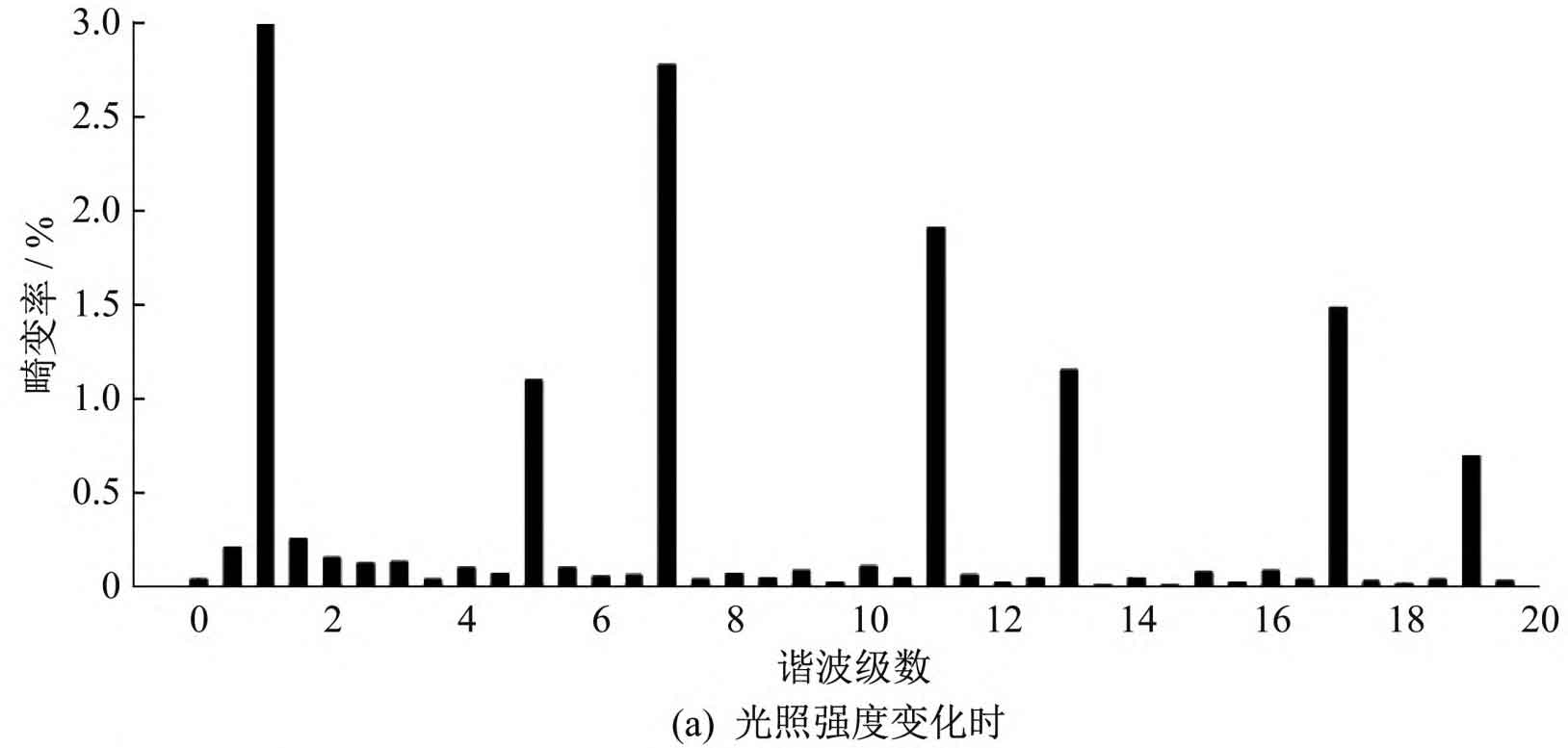
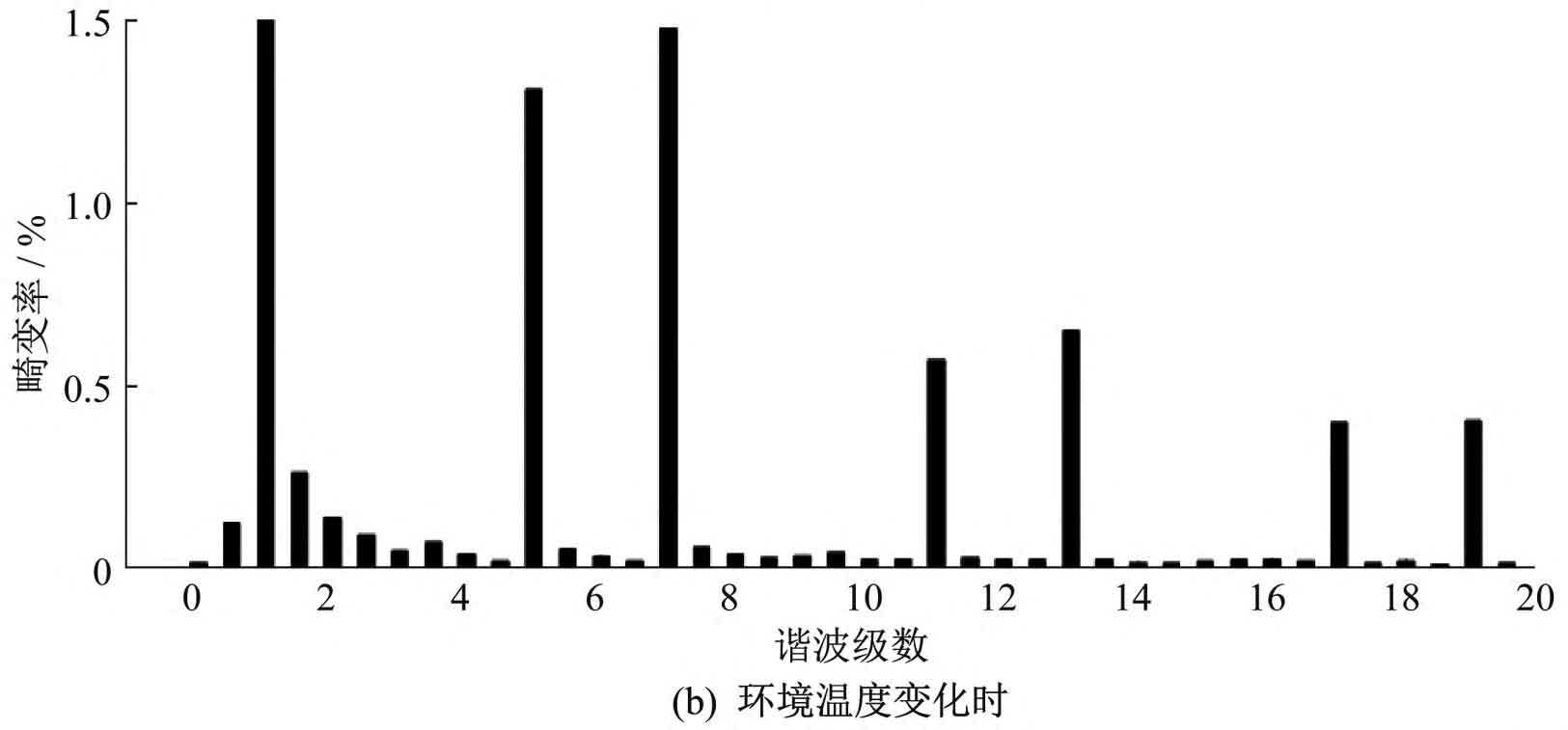
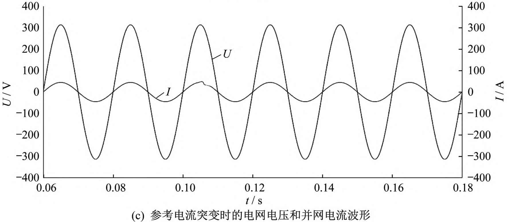
From Figure 9 (a) and Figure 9 (b), it can be seen that when the light intensity and external environmental temperature change, the grid current and grid voltage are in the same frequency and phase, and the total harmonic distortion rate of the grid current waveform is 3.01% and 2.28%, both of which are less than 5%, meeting the grid connection requirements. From Figure 9 (c), it can be seen that under the composite control strategy, when the system reference current suddenly changes, after 0.01 seconds, the grid connected current waveform returns to stability, indicating that the control strategy has good dynamic responsiveness.
5. Conclusion
This article proposes to coordinate and unify the control of photovoltaic inverters and active inverters, using the ip-iq harmonic detection method based on instantaneous reactive power theory to detect and track the system’s harmonics. Taking into account the advantages and disadvantages of PR control and repetitive control, a composite control strategy is composed of quasi PR control and improved repetitive control to control the grid current. Simulations were conducted on repetitive control, PR control, and composite control strategies in MATLAB/Simulink environments. The results showed that compared to using a single repetitive control and PR control, the composite control strategy proposed in this paper has the advantages of good dynamic response of quasi PR control, as well as the ability of repetitive control to effectively suppress grid harmonics, improving the quality of grid connected current waveform, Complies with grid connection requirements, achieves coordinated and unified control of photovoltaic inverters and active filters, and improves the power quality of the power grid.