
Large capacity energy storage can eliminate the adverse effects of fluctuations, randomness, and anti peak characteristics of new energy generation on the power grid. The battery energy storage system based on modular multilevel converter (MMC) has received increasing research due to its advantages of modularity, decentralization, and high voltage and large capacity.
Existing research mostly focuses on the MMC based battery energy storage system (MMC BESS) where each submodule is connected to an energy storage battery. As a three terminal system, modular multilevel converter based battery energy storage system can facilitate the interconnection and decoupling of AC and DC systems, while also exerting the energy storage function of batteries to achieve power suppression and buffering. The basic control strategy is to obtain the current dq axis reference value through the outer loop control, and then use the inner loop control to achieve rapid response of the current, achieving decoupling control of active and reactive power. The research focus is mostly on the management of energy storage batteries, and a discrete time domain power prediction model for battery state of charge is proposed to achieve real-time dynamic control. The system has fast response speed and accurate current tracking. The existing operation control is aimed at the topology where all submodules are connected to energy storage batteries, and traditional double closed-loop control is mostly used. The entire system has a large number of batteries, which are bulky and expensive, resulting in increased costs and waste of battery capacity when the energy storage demand is not very high.
The price of battery energy storage systems mainly consists of battery packs, battery management systems, energy management systems, energy storage converters, and other electrical equipment prices. Reducing the capacity of each submodule’s energy storage battery can reduce costs to some extent, but the two are not proportional, that is, the cost reduction ratio will be smaller than the battery capacity reduction ratio, and the required battery management system will not be reduced. Therefore, a few scholars at home and abroad have begun to study the partial integration of MMC with partially integrated BESS (MMC PBESS) into battery energy storage systems, which can effectively reduce energy storage costs while meeting the energy storage ratio requirements. In addition, modular multilevel converter with partly integrated battery energy storage systeman provide inertia for the power grid with gradually deepening power electronics, and has good application prospects in auxiliary services such as primary frequency regulation and black start, which do not require significant energy storage capacity. The Fujian modular multilevel converter based battery energy storage system project, supported by the State Grid Headquarters project, is currently under construction. Therefore, modular multilevel converter with partly integrated battery energy storage system, which reduces the number of batteries on the basis of modular multilevel converter based battery energy storage system, also has application prospects and value. Its corresponding firefighting and other supporting measures have been studied and applied in existing energy storage stations and MMC converter stations.
Modular multilevel converter with partly integrated battery energy storage system can be specifically divided into three topologies: partial molecular module energy storage, battery stack parallel branch energy storage, and inductance parallel branch energy storage. The first topology does not change the original structure of the MMC energy storage system, and there are different implementation forms such as half of the submodules connected to energy storage, a certain phase connected to energy storage, and a certain bridge arm connected to energy storage. Existing research has solved the internal imbalance problem caused by partial energy storage by injecting circulating current, which is achieved through the DC component of the circulating current to achieve inter phase energy balance and the AC component to achieve inter phase energy balance. However, the calculation of circulating current is cumbersome and the injection of circulating current increases the complexity of system control. The control strategies of each bridge arm are coupled, lacking targeted topology forms. The modular multilevel converter with partly integrated battery energy storage system based on a certain phase connected energy storage system proposes a battery or grid control method, which achieves battery balance by changing the given value of battery current. However, the battery in the energy storage submodule is connected through a chopper circuit, resulting in complex control. The relationship between the connection ratio, modulation ratio, and grid connected power factor of energy storage batteries under the constraints of capacitor voltage balance and modulation range has been studied, but no further optimization and improvement have been made to its control strategy. The literature on modular multilevel converter with partly integrated battery energy storage system mentioned above shows that although the topology structure is different from traditional MMC, the capacitor voltage balancing strategy of its capacitor part is the same as that of traditional MMC. For example, the average voltage of the bridge arm capacitor based on carrier phase shift modulation and the sub module capacitor voltage are controlled by PI to change the modulation waveform to achieve capacitor voltage balance; The closed-loop sorting algorithm based on nearest level approximation determines the number of submodules that need to be input based on the nearest level approximation. When charging the submodules, the corresponding number of submodules with the lowest voltage is input, and when discharging, the corresponding number of submodules with the highest voltage are input, thus achieving capacitor voltage balance; The outer loop control of capacitor voltage takes the total sub module capacitor voltage of the bridge arm as the control target to generate the reference value of the current inner loop. Additional measures such as sorting and balancing algorithm need to be taken to balance the capacitor voltage inside the bridge arm; There are also control strategies such as additional sub modules, switching matrix self balancing, and circulation injection.
Analysis and control method research have been conducted on the modular multilevel converter with partly integrated battery energy storage system with lower bridge arm connected to energy storage batteries. Half of the sub modules can not only reduce energy storage costs, but also support DC voltage in the event of AC side short circuits. This control method is also applicable to the topology of upper bridge arm connected to energy storage batteries. Even adding batteries to each phase can also achieve half of the sub module energy storage, but its control strategy needs to consider factors such as modulation wave distribution, which is more complex and has been studied by scholars. The first part of the article introduces the modular multilevel converter with partly integrated battery energy storage system topology and its mathematical and circuit models for connecting the lower bridge arm to the energy storage battery; The second part provides the control strategy and operational boundaries of modular multilevel converter with partly integrated battery energy storage system; The third part compares and analyzes the simulation results of modular multilevel converter with partly integrated battery energy storage system on the MATLAB/Simulink platform; The fourth part presents the research results.
1. MMC-PBESS modeling for connecting the lower bridge arm to the battery
The modular multilevel converter with partly integrated battery energy storage system topology of the lower bridge arm connected to the energy storage battery is shown in Figure 1 (a).
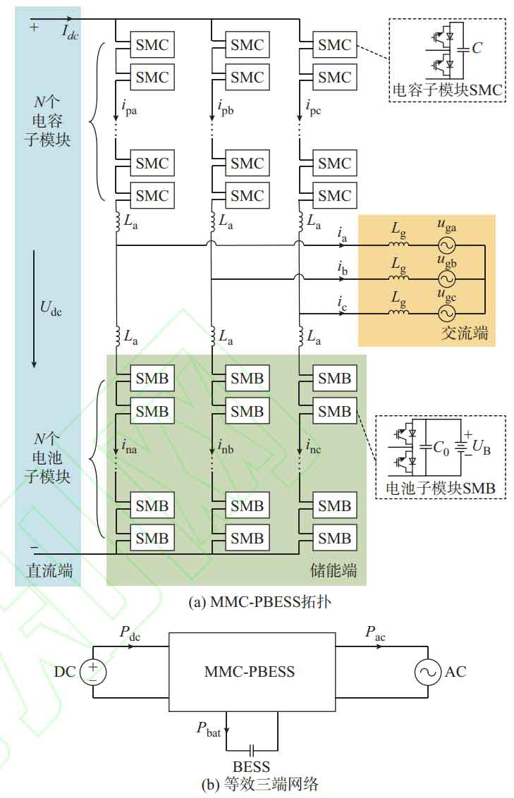
This topology is similar to the traditional MMC topology structure, consisting of three phases and six bridge arms. Each bridge arm is composed of N sub modules SMC or SMB and a bridge arm inductance La in series, all of which are half bridge sub modules. Among them, ij (j=a, b, c) is the current of the j-phase AC bus; Ipj and inj represent the upper and lower arm currents of phase j, respectively; Idc is the DC bus current; Ugj is the grid connection voltage on the intersecting current side of j; Udc is the DC voltage; UB is the voltage of the submodule battery; Lg is the grid connected inductance on the AC side; C is the capacitance of the capacitor submodule; C0 is the capacitance of the battery in parallel in the battery submodule. The difference is that each phase of the lower bridge arm submodule in this topology is connected to an energy storage battery, expanding the traditional MMC into a three-port network, as shown in Figure 1 (b), which can achieve power exchange at the DC, AC, and energy storage ends. Among them, Pdc, Pac, and Pbat are the DC, AC, and energy storage powers of modular multilevel converter with partly integrated battery energy storage system, respectively. The direction indicated by the arrow is positive, ignoring circuit losses. The three satisfy the constraint Pdc – Pac=Pbat.
1.1 MMC-PBESS DC side model
The DC bus current is evenly divided in three phases:
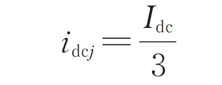
In the formula, idcj is the direct current component in the upper/lower bridge arm current of phase j. Let u nj and u pj be the total equivalent voltage of the sub modules of the lower and upper bridge arms of the j phase, respectively. The Kirchhoff voltage law equation on the DC side of modular multilevel converter with partly integrated battery energy storage system can be listed:
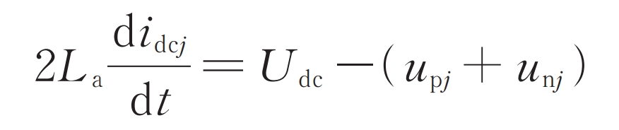
The formula is the DC side mathematical model of modular multilevel converter with partly integrated battery energy storage system. In addition, there are the following constraints between the battery voltage of the lower bridge arm submodule and the DC bus voltage.

1.2 MMC-PBESS AC side model
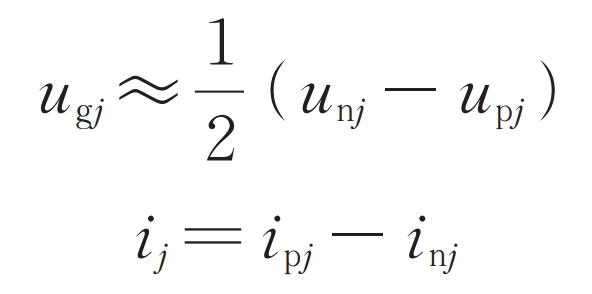
There is a voltage and current relationship between the upper and lower bridge arms and the AC bus.
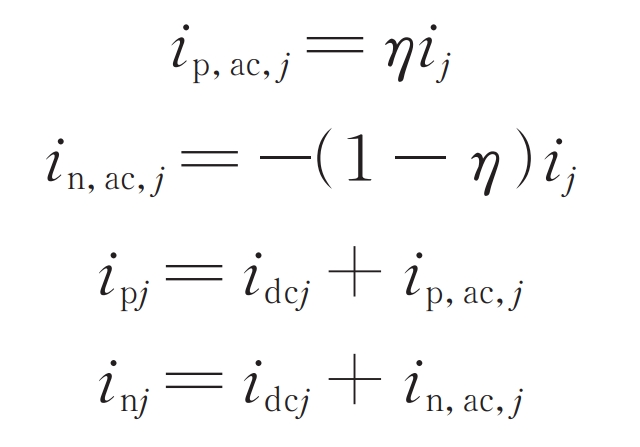
The upper and lower bridge arms of modular multilevel converter with partly integrated battery energy storage systemare asymmetric, so the AC bus current cannot be evenly distributed between the two bridge arms like traditional modular multilevel converter based battery energy storage system. Let the AC components in the bridge arm current of phase j be ip, ac, j, and their proportion to the AC bus current be η ∈ (0, 1); The AC components in the lower bridge arm current of phase j are in, ac, j, and their proportion to the AC bus current is 1- η, Namely:
Taking phase A as an example, the KVL equations of the upper and lower bridge arm circuits can be obtained from the topology diagram:
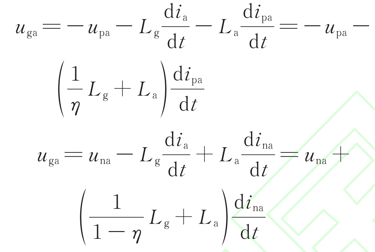
In the equation, t is the time variable.
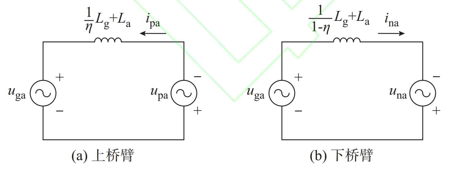
The formula is the AC side mathematical model of modular multilevel converter with partly integrated battery energy storage system. The equivalent circuits on the AC side of the upper and lower bridge arms of the topology A can be obtained as shown in Figure 2 (a) and (b), respectively.
2. MMC-PBESS sub control method for connecting the lower bridge arm to the battery
2.1 Sub module capacitor voltage balancing control
During system operation, the power on the AC and DC sides cannot be kept balanced at all times, and the capacitors of each submodule are independent of each other, and the switching conditions of each switch cannot be completely consistent. Therefore, the capacitor submodules may experience overcharging or discharging, and there may be capacitor voltage imbalance between different submodules.
Therefore, it is necessary to balance the voltage of the sub module capacitors, that is, adjust the DC or AC current based on the deviation of the sub module capacitor voltage from the reference value, in order to maintain the charge discharge balance of the capacitor bridge arm in real-time. This study aims to verify in experiments, so the voltage level is not very high and the number of bridge arm submodules is relatively small. Therefore, carrier phase shift modulation is used to achieve better harmonic characteristics of the output waveform. The following capacitor voltage equalization control essentially changes the modulation wave of carrier phase shift modulation.
2.1.1 Principle of capacitor voltage balance
Taking phase A as an example, ignoring secondary and higher frequency circulating currents, the upper bridge arm current and voltage can be expressed as:
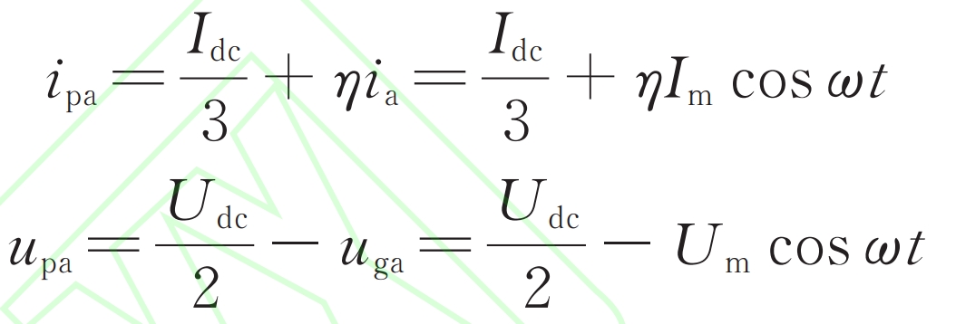
In the formula, Im and Um respectively represent the amplitude of AC grid connected current and voltage; ω Is the power frequency angular frequency.
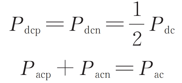
Multiplying the formula on the same side can obtain the DC component of the upper bridge arm power as Udc Idc/6- η ImUm/2, then the condition for capacitor voltage balance is that the DC component is zero, which can also be expressed as:

In the formula, Pdcp and Pacp are the AC and DC power borne by the three-phase upper bridge arm. When only the DC power and AC power of the upper bridge arm circuit are equal, the upper bridge arm power has no DC component, and the capacitor voltage can be balanced.
2.1.2 arm average voltage control
The DC component in the bridge arm current charges the submodule capacitor when the submodule is put into operation, so adjusting the value of this DC component can control the charging of the submodule capacitor.
Specifically, taking phase A as an example, define the average voltage ua, p, av of the bridge arm capacitance on phase A as:
In the formula, uapi is the capacitance voltage value of the i-th sub module of the A-phase upper bridge arm. The control objective is to maintain ua, p, and av at the capacitor voltage setting values uc and ref. After subtracting uc, ref and ua, p, and av, the output is added to the reference value of the DC component of the bridge arm current in the DC control through a PI controller.
When the average voltage of the bridge arm is less than the set value of the capacitor voltage, the reference value of the DC component of the bridge arm current increases. Under closed-loop control, the actual DC component of the bridge arm current increases, and the sub module capacitor is charged. The average voltage of the bridge arm increases, thus achieving control of the average capacitor voltage of the bridge arm.
2.1.3 submodule capacitor voltage control
The capacitor voltage between submodules within the bridge arm may also be unbalanced, so it is necessary to independently balance the capacitor voltage of each submodule.
When the bridge arm current is positive, if the capacitor voltage of the submodule is too small, the input time will be extended; If the capacitor voltage of the submodule is too high, reduce its input time. The reverse is also true. The change in input time is determined by the independent modulation wave size of the submodule, that is, the capacitor voltage size can be controlled by changing the modulation wave of the submodule.
When the bridge arm current is positive, after subtracting uc, ref, and uapi, the output is added to the modulation wave of the submodule through a PI controller; When the bridge arm current is negative, subtract uc, ref, and uapi and take the inverse through the PI controller. The output is added to the modulation wave of the submodule.
2.2 Split control strategy for upper and lower bridge arms
The topology shown in Figure 1 is symmetrical between the three phases, so from the DC side, the DC bus current is evenly distributed in the three phases. The DC side control strategy is no different from the traditional strategy applied to MMC. The reference value of the DC bus current is calculated by giving the DC power Pdc, and then the internal loop control is used to achieve fast response.
The traditional strategy controls the current of the AC bus, with the upper and lower bridge arms parallel from the AC side. Due to the symmetry of the upper and lower bridge arms of the MMC, the bus current is naturally evenly distributed between the two bridge arms. Unlike MMC, the topology of the upper and lower bridge arm submodules in this article is different. Therefore, the upper and lower bridge arms are asymmetric, and the AC bus current cannot be evenly divided between the two bridge arms. Using traditional strategies will result in fundamental frequency components in the circulation.
The presence of batteries in the topology enables decoupling of AC and DC side control, meaning that AC and DC power can be unequal. When the AC and DC power of the system is unequal, batteries are needed to play a role in energy storage. The traditional strategy applied to MMC does not decouple AC and DC, and cannot fully utilize the energy storage function of batteries. Therefore, it is necessary to independently control the current of the upper and lower bridge arms. This article defines this independent control strategy as a separate control strategy, which can play the charging and discharging functions of the lower bridge arm battery while meeting the voltage balance of the upper bridge arm capacitor.
Perform dq axis transformation on the two loops of the three-phase upper and lower bridge arms shown in Figure 2, using dual closed-loop control. The outer ring is a constant power control, and the total d-axis component reference value ID of the AC bus can be calculated from the AC power reference value Pac and the AC grid connected voltage amplitude Um:
The inner loop is controlled by the bridge arm current, using AC grid connected voltage feedforward and dq axis decoupling control, with an equivalent inductance of Lg/ η + La or Lg/(1- η )+ La, achieving fast response of upper and lower bridge arm currents. Assuming a power factor of 1, the focus of the sub control strategy is the selection of the d-axis reference value for the bridge arm current:

In the formula, IDp is the reference value of the d-axis component of the bridge arm current ipj on phase j; IDn is the reference value of the d-axis component of the bridge arm current inj under phase j.
The bottom modulation strategy uses carrier phase shift modulation, which can obtain a higher equivalent switching frequency when the sub module switching frequency is low, making it very suitable for modular multilevel converter with partly integrated battery energy storage system. The modulation waves ump and umn of the upper and lower bridge arms are composed of the DC component umdc and the AC component umac, p, umac, n:
In the formula, umdc is the DC component of the bridge arm modulation wave; Umac, p, umac, n are the AC components of the upper and lower bridge arm modulation waves, respectively. UMDC, UMAC, p, and UMAC, n are generated by DC side control and AC side sub control, respectively.
According to the formula, in order to ensure the voltage balance of the upper bridge arm capacitor, the amplitude of the AC component of the upper bridge arm current η Im is the fixed value, and when converted to the dq axis, the reference current IDp is the fixed value. Considering the modulation ratio m=2Um/Udc ≈ 1, the umac generated by the upper bridge arm control, p, is approximately equal to umdc/2. The half bridge submodule cannot output negative voltage. In order to ensure that the lower bridge arm half bridge submodule is within the normal modulation range, umac, n must be less than or equal to umdc/2, that is, less than or equal to umac, p. The selection of the lower bridge arm IDn must meet the following constraints:

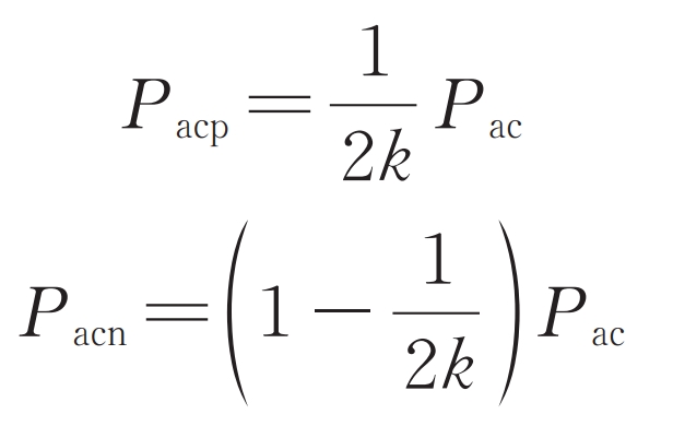
The specific values of IDp and IDn are related to the ratio of system AC/DC power. Let k be the ratio of system AC/DC power, and consider the case where Pac=kPdc (Pdc ≥ 0), that is, the DC side delivers power to modular multilevel converter with partly integrated battery energy storage system, which operates in inverter mode. The AC and DC power borne by the lower bridge arm is defined as Pacn and Pdcn, respectively, indicating the following relationship between AC and DC power:
With the goal of maintaining the balance of capacitor voltage in the upper bridge arm submodule, there are the following constraints between the AC and DC power of the upper bridge arm:

From this, we can obtain:
When k=0, there is a short circuit on the AC side, and all power on the DC side is absorbed by the energy storage battery. At this point, the upper bridge arm is short circuited, and all the sub modules of the lower bridge arm battery are put into operation to support the DC side voltage.
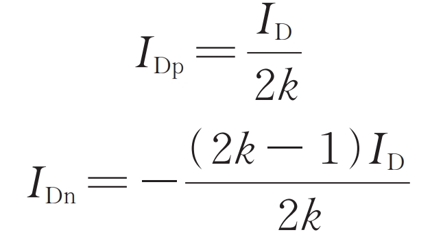
When k ≠ 0, it can be obtained from equations:
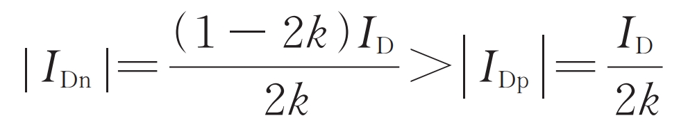
1) K<0
Both the AC and DC sides input power to modular multilevel converter with partly integrated battery energy storage system, and at this time, the ID is less than 0, which does not meet the constraints of the formula, and the half bridge submodule system cannot operate normally. At this point, in order to ensure that the lower bridge arm submodule can operate in a negative voltage state, the half bridge submodule can be changed to a full bridge submodule. However, as the number of power devices increases and the cost increases, this article will not consider it.
2) 0<k<0.5
The AC power is less than half of the DC power, IDp>ID>0, IDn>0, and the excess AC power transmitted by the upper bridge arm is absorbed by the lower bridge arm battery.
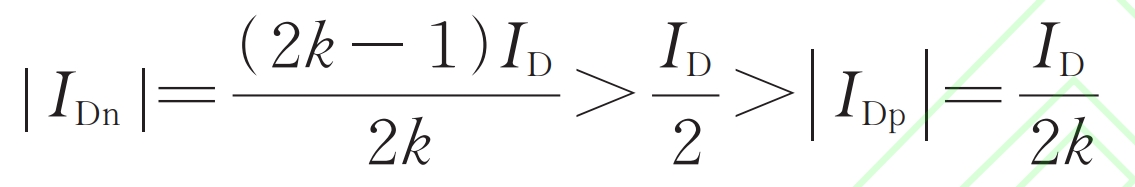
3) 0.5 ≤ k<1
The AC power is greater than or equal to half of the DC power, 0<IDp<ID, – ID<IDn<0, and the lower bridge arm battery provides a small portion of AC power.
4) K=1
The AC and DC power are equal, and the battery does not play a role in energy storage. The entire system utilizes the role of traditional MMC to achieve the conversion of AC and DC power.
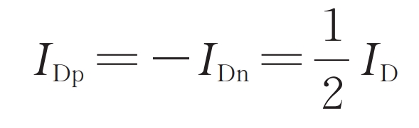
It can be seen that the fundamental frequency component of the upper and lower bridge arm currents is forcibly controlled to half of the AC bus current, eliminating the fundamental frequency component of the circulating current.
5) K>1
AC power is greater than DC power, at which point:
The half bridge submodule system cannot operate normally without meeting the constraints of the formula.
In summary, when Pac=kPdc (Pdc ≥ 0), the normal operating range of the half bridge submodule modular multilevel converter with partly integrated battery energy storage system is 0<k ≤ 1. The selection rules for IDp and IDn are shown in Figure 3.
The modular multilevel converter with partly integrated battery energy storage system and its control strategy proposed in this article can achieve phase separation control similar to STATCOM. However, the three-phase AC equivalent circuit of modular multilevel converter with partly integrated battery energy storage system in this article is a parallel connection of two star shaped circuits. Although the three-phase can be controlled separately, there are constraints and coupling between the three, that is, regardless of the three-phase voltage, the total three-phase output port voltage needs to be kept constant at all times.
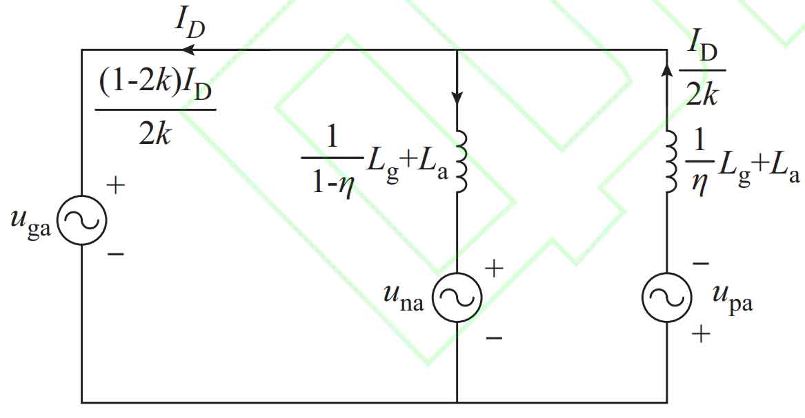
The above sub control strategy can also be applied to achieve low voltage ride through in the event of AC side faults in modular multilevel converter with partly integrated battery energy storage system. Assuming Pac=kPdc (Pdc ≥ 0, 0<k ≤ 1) during normal operation μ The ratio of the AC side voltage during a fault to the AC side voltage during normal operation, then the AC side voltage drops to μ Um (0.2 ≤ μ < 1). In order to maintain the constant current of the AC bus and achieve low voltage crossing, the reference values of the d-axis components of the upper and lower bridge arm currents are changed after the fault occurs as follows:
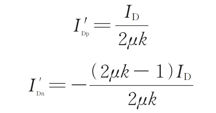
In the formula, I’Dp and I’Dn are the d-axis component reference values of the system’s upper and lower bridge arm currents after the fault occurs.
After a fault occurs, changing the reference value of the bridge arm current can utilize the charging function of the energy storage battery to absorb surplus power on the DC side and achieve low voltage ride through on the AC side of the modular multilevel converter with partly integrated battery energy storage system Of course, traditional MMC AC fault traversal methods can also be used. For DC side faults, the half bridge submodule in this topology does not have DC fault traversal capability. The handling method for DC side faults is the same as the traditional half bridge submodule MMC, which can limit the current by quickly connecting the limiting resistor and inductor in series to the flow path of DC current after a fault, or by paralleling thyristors at both ends of the submodule to limit the current. The content of AC/DC fault handling is complex and has been extensively studied in literature, so this article will not elaborate on it.
3.Simulation verification
In order to verify the correctness of the above analysis and lay the foundation for subsequent experimental platform construction, an modular multilevel converter with partly integrated battery energy storage system with N=16 bridge arm submodules was built on MATLAB/Simulink. The three-phase upper bridge arm submodules were all connected to capacitor C, and the lower bridge arm submodules were all connected to energy storage battery B. The system parameters are shown in Table 1.
| Reference | Value |
| La | 2 mH |
| Lg | 1 mH |
| C | 10 mF |
| uc,ref | 48 V |
| UB | 48 V |
| UDC | 750 V |
| Um | 311 V |
| ω | 100π rad/s |
3.1 Verification of capacitor voltage balance
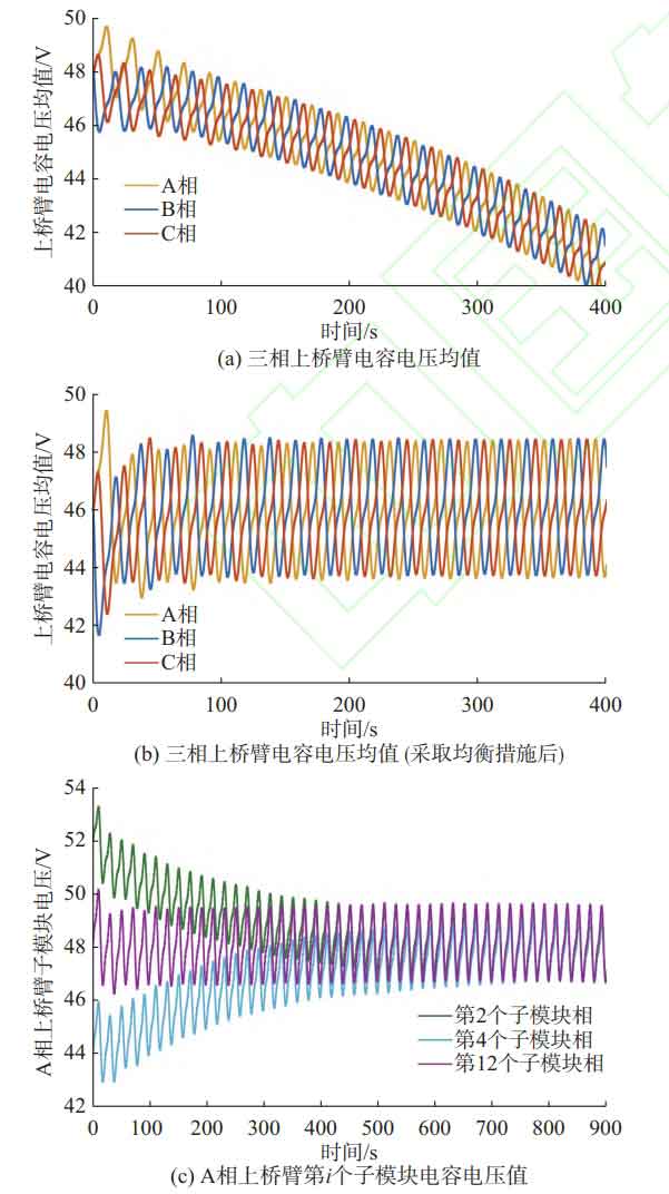
Set the system to have equal AC and DC power, without taking any capacitor voltage balancing measures. The simulation results of the average voltage of the three-phase upper bridge arm capacitor are shown in Figure 4 (a). It can be seen that due to the internal equivalent resistance of the system consuming some DC power, there is an over discharge phenomenon in the upper bridge arm submodule capacitor, and the system cannot operate stably.
3.1.1 Verification of Bridge Arm Average Voltage Control
Firstly, verify the control effect of the average voltage of the bridge arm. The reference value of the capacitor voltage is 48 V, and the simulation results are shown in Figure 4 (b). It can be seen that after about 4 cycles (0.08 seconds), the average voltage of the bridge arm capacitor stabilizes at around 48 V, indicating that the capacitor is no longer over discharged, and the amplitude of the capacitor voltage fluctuation is about 2.4 V, mainly based on the fundamental frequency.
3.1.2 Verification of sub module capacitor voltage control
Secondly, verify the control effect of the sub module capacitor voltage. Set the initial capacitance voltage of the second submodule of the A-phase upper bridge arm to 52 V, the initial capacitance voltage of the fourth submodule to 44 V, and the capacitance value of the 12th submodule to 80% of the capacitance values of other submodules (i.e. 8mF). The simulation results are shown in Figure 4 (c). The capacitance voltage of the second submodule gradually decreases and stabilizes at around 48 V after 0.7 seconds; The capacitance voltage of the fourth submodule gradually increases and stabilizes at around 48 V after 0.7 seconds; The 12th submodule stabilized at around 48 V after 0.08 seconds, with a capacitance voltage fluctuation amplitude of approximately 2.9 V. It can be seen that the smaller the capacitance value, the greater the capacitance voltage fluctuation.
3.2 Verification of upper and lower bridge arm split control
Let Pdc=10 kW, calculate Idc=Pdc/Udc ≈ 13.33 A, idcj=Idc/3 ≈ 4.44 A. Firstly, simulate the case of 0<k<0.5, taking k=0.4. The simulation results of the AC/DC bus current and the A-phase bridge arm current are shown in Figure 5 (a). It can be seen that the amplitude of the AC bus current is well controlled at Im=2Pac/(3Um) ≈ 8.6 A, while the DC bus current is stable around 14 A under capacitor voltage balance control, slightly higher than the theoretical value of 13.33 A. According to the formula, IDp=1.25ID is calculated, so the amplitude of the AC component of the upper bridge arm current is 1.25Im=10.75 A; According to the formula, IDn=0.25ID is calculated, so the amplitude of the AC power of the lower bridge arm current is 0.25Im=2.15 A. The AC components of the upper and lower bridge arms are in the same direction, and the AC bus current Im=IDp – IDn=8.6 A. Figure 5 (a) shows the simulation results of the system for 0.06 s or three power frequency cycles, which are consistent with the calculation results. The bridge arm current is superimposed on the DC component of about 14/3 ≈ 4.67 A, and the AC bus current is the difference between the upper and lower bridge arm currents.
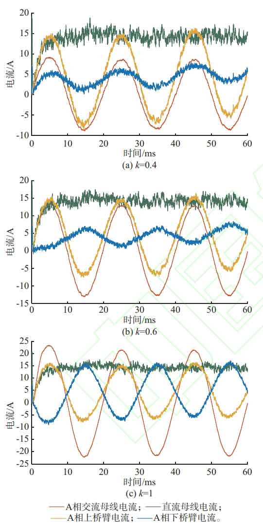
Next, simulate the case of 0.5 ≤ k<1, taking k=0.6. The simulation results of the AC/DC bus current and the A-phase bridge arm current are shown in Figure 5 (b). It can be seen that the amplitude of the AC bus current is well controlled at Im=2Pac/(3Um) ≈ 12.86 A, and the DC bus current is stable around 14 A under capacitor voltage balance control. According to the formula, IDp=0.83ID is calculated, so the amplitude of the AC component of the upper bridge arm current is 0.83Im=10.67 A; According to the formula, IDn=-0.17ID is calculated, so the amplitude of the AC component of the lower bridge arm current is 0.17Im=2.19 A. The AC components of the upper and lower bridge arms are reversed, and the AC bus current Im=IDp – IDn=12.86 A. Figure 5 (b) shows the simulation results of the system for 0.06 s or three power frequency cycles, which are consistent with the calculation results. The bridge arm current is superimposed on the DC component of about 4.67 A, and the AC bus current is the difference between the upper and lower bridge arm currents.
Finally, simulate the case where k=1, and the simulation results of the AC/DC bus current and the A-phase bridge arm current are shown in Figure 5 (c). It can be seen that the amplitude of the AC bus current is well controlled at Im=2Pac/(3Um) ≈ 21.44 A, and the DC bus current is stable around 14 A under capacitor voltage balance control. According to the formula, IDp=0.5ID is calculated, so the amplitude of the AC component of the upper bridge arm current is 0.5Im=10.72 A; According to the formula, IDn=-0.5ID is calculated, so the amplitude of the AC component of the lower bridge arm current is 0.5Im=10.72 A. The AC components of the upper and lower bridge arms are reversed, and the AC bus current Im=IDp – IDn=21.44 A. Figure 5 (c) shows the simulation results of the system for 0.06 s or three power frequency cycles, which are consistent with the calculation results. The bridge arm current is superimposed on the DC component of about 4.67 A, and the AC bus current is the difference between the upper and lower bridge arm currents.
Through the above analysis, it can be found that regardless of the proportion of AC and DC power, the waveform of the upper bridge arm current remains unchanged. The DC component represents the DC power borne by the upper bridge arm, and the AC component represents the AC power borne by the upper bridge arm. The two are coupled, so the AC component is also a fixed value when the DC power is fixed. The AC component of the lower bridge arm current changes with the value of k, representing the charging function of the energy storage battery. When its phase is opposite to the upper bridge arm current, the battery absorbs some DC power from the lower bridge arm during charging; When its phase is the same as the current of the upper bridge arm, the battery charges and absorbs all DC power from the lower bridge arm and some AC power from the upper bridge arm. The size of the circulating current is equal to half of the sum of the upper and lower bridge arm currents. When 0<k<0.5, the upper and lower bridge arm currents are in the same direction, and the circulating current is at its maximum, additional circulating current suppression measures need to be taken.
3. Conclusion
This article conducts mathematical modeling and analysis of the upper and lower bridge arm AC circuit of the modular multilevel converter with partly integrated battery energy storage system topology with the lower bridge arm connected to the battery. The effectiveness of the capacitor voltage balance strategy and the proposed upper and lower bridge arm control strategy are verified on MATLAB/Simulink. This control strategy can suppress the fundamental frequency component of the circulating current when the AC and DC power of the system are equal, and exert the charging function of the battery when the AC and DC power of the system are unequal. It is also applicable to the modular multilevel converter with partly integrated battery energy storage system topology where the upper bridge arm is connected to the battery, and also applies to higher voltage levels using nearest level approximation modulation. Compared with existing circulating current injection methods, it achieves decoupling control of the upper and lower bridge arms, which facilitates independent control and management of capacitor and battery submodules and is simpler. The applicable conditions for this strategy are given when the DC power is positive, that is, it can be applied when the AC power is greater than zero and less than or equal to the DC power. The half bridge submodule modular multilevel converter with partly integrated battery energy storage system can achieve flexible inversion and achieve the flow of DC power to the energy storage and AC terminals while maintaining capacitor voltage balance.
The control strategy proposed in this article is only applicable to the half bridge submodule modular multilevel converter with partly integrated battery energy storage system with upper/lower bridge arm energy storage for DC side power inflow, and does not consider battery charge balance and power device stress issues. Subsequent research will expand on this.