
In order to cope with the increasing demand for electricity and environmental pressure, the power system is forming a development trend of high proportion of new energy and high proportion of power electronic equipment (i.e. “dual high”). With the increasing penetration rate of new energy and power electronic equipment, the power system has a trend of decreasing inertia and weakening system strength, and stability issues are becoming increasingly serious. Grid forming (GFM) control technology can improve the voltage and frequency support capabilities of converters and enhance the stability of power systems. On the other hand, the role of energy storage systems in the power grid includes providing active or reactive support for the system, improving the grid connection capacity of new energy, participating in peak shaving and frequency regulation, and providing short-term power supply during faults. The use of grid control technology to control energy storage converters can improve the stability of new power systems. Therefore, the stability of the energy storage system itself is particularly crucial, and its insulation and withstand voltage level is an important indicator for testing stability. The partial discharge of electrical equipment in the power system, regardless of its form, whether it occurs internally or on the surface, will correspondingly damage the insulation of the equipment. Partial discharge caused by suspension, partial discharge caused by bubbles, and tip discharge caused by conductor tips may all have different effects on electrical equipment.
Currently, there is not much research on energy storage battery systems in China. China Electric Power Research Institute has established a second-order common mode equivalent circuit model suitable for energy storage systems and conducted research on the common mode voltage and current of battery systems; In collaboration with the School of Automation at Nanjing University of Technology and Shanghai Institute of Shipbuilding Equipment, a bidirectional active balancing system for energy storage battery modules based on bidirectional flyback converter is proposed to address the issues of poor consistency between modules and imbalanced electricity consumption. This effectively reduces the imbalance of electricity consumption.
Mainly focusing on research on improving the reliability of energy storage battery units. The insulation and withstand voltage boundaries of energy storage battery systems and their high altitude application capabilities were verified through experiments, and the impact of wire harness discharge on the insulation and withstand voltage performance of battery systems was explored, providing guidance for the development and application of energy storage battery systems in the future.
1. Reliability of energy storage battery unit
1.1 Energy storage system and structure
The energy storage system has only four parts, namely energy storage batteries, energy storage converters (PCS), energy management systems (EMS), and battery management systems (BMS). The main devices of the BMS system include BMU (battery module management unit), BCMU (battery cluster management unit), BSMU (battery stack management unit), high-voltage control box, LCD screen device, etc. The specific configuration is carried out according to the engineering design. The energy storage battery unit includes: batteries, battery pack related structures, wiring harnesses, battery pack management units, and other parts.
1.2 Insulation withstand voltage and partial discharge
Insulation withstand voltage test is a technical means to inspect and evaluate the insulation withstand voltage capability of electrical equipment. Any local damage to the insulation structure will cause the entire equipment to lose insulation performance. Therefore, the overall insulation capacity of the equipment can generally only be represented by the test voltage (in kV) that can withstand.
Partial discharge phenomenon mainly refers to the discharge that occurs locally in the insulation of power equipment under the action of a sufficiently strong electric field. According to the statistics of the power grid, partial discharge is an important cause of insulation breakdown in high-voltage electrical equipment and an important indicator of insulation degradation. At a standard atmospheric pressure of 20 ℃, pressure of 101325 Pa, and absolute humidity of 11 g/m3, it is generally believed that the uniform electric field air gap breakdown field strength is 30 kV/cm, which means that a distance of 1 cm requires a voltage of 30 kV to breakdown, and a distance of 1 mm requires a voltage of 3 kV to breakdown.
Partial discharge generally includes corona discharge, arc discharge, surface discharge, and air gap (internal) discharge. Among them, air gap (internal) discharge is usually caused by defects in solid insulation such as cables, bushings, GIS joints, etc. Air gap discharge is highly destructive to insulation and usually continues to expand until they cause complete failure.
This study on the insulation and withstand voltage performance of energy storage battery units mainly focuses on the insulation and withstand voltage test verification of the battery itself, battery structure, wiring harness, and battery management unit, and explores the impact of local insulation defects in wiring harness on insulation and withstand voltage.
2. Test principle and plan
2.1 Principles of Electrical Testing
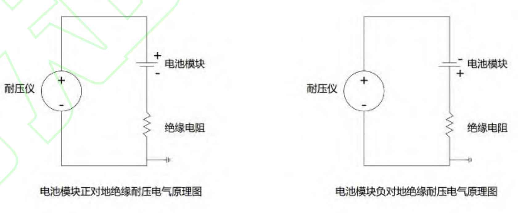
The insulation and withstand voltage electrical principle of the energy storage battery module is shown in Figure 1. The electrical principles of insulation and withstand voltage performance are consistent, but the evaluation indicators and test voltage are different. The evaluation index of insulation performance is the insulation resistance under a certain test voltage; The evaluation index of withstand voltage performance is the leakage current at a certain test voltage. The operating voltage is divided into power frequency AC voltage and DC voltage. As the battery module itself is a DC power supply, DC voltage is used as the test voltage. Although the electrical principles of insulation and withstand voltage are the same, the assessment indicators are different, so separate assessment tests are conducted on insulation and withstand voltage. In addition, in order to ensure the completeness of the test, this test assesses the insulation and withstand voltage capabilities of the battery module, positive to ground and negative to ground, respectively.
2.2 Electrical Test Plan
The energy storage battery module is composed of a battery body (structural component+module), a secondary acquisition cable, and a BMU. The lowest level of insulation and withstand voltage among the three determines the upper limit of the insulation and withstand voltage of the energy storage battery module. Using a hierarchical decoupling and step-by-step stacking approach, insulation and voltage withstand tests were conducted on the battery body, secondary acquisition cables, and BMU.
According to GB/T 36276-2018, lithium-ion batteries for power storage (with a working voltage of 1.5 kV) are insulated to the national standard of 2.5 kV. Due to the special nature of the battery system (active system), during the actual insulation or withstand voltage process, it is necessary to first verify whether there is a potential superposition state, and whether there is a continuous increase in the actual insulation and withstand voltage potential during the continuous series connection of battery modules.
If there is a potential superposition, for a 1500 V system, the end of the system is subjected to a voltage of nearly 4000 V. Considering a factor of 1.1, the insulation standard needs to reach 4.4 kV.
According to the national standard for withstand voltage of 3.8 kV, based on the altitude withstand voltage relationship, for external insulation of equipment at altitudes above 1000 m but not exceeding 4000 m, the insulation strength decreases by about 1% for every 100 m increase in altitude.
This time, considering the insulation and voltage resistance at an altitude of 4800 meters, as most electrical equipment with an altitude of 35 kV and below has a certain margin for external insulation, considering below 4000 meters, according to formula 1, the required voltage resistance strength is 7400 V.
2.2.1 Insulation Test Plan
Collect the temperature and voltage of the energy storage battery through backend connection to BMS. After the data is normal, conduct insulation resistance testing according to the working conditions in Table 1. Set the voltage to the test standard value for 60 seconds, and record the insulation resistance value. After each test, the residual charge of the battery module needs to be released.
| Working conditions | Insulation resistance/MΩ | Remarks |
| Battery module+BMU tooling | Positive pole to ground | No breakdown or flashover occurs |
| Battery module+BMU tooling | Negative electrode to ground | No breakdown or flashover occurs |
| Battery module+BMU | Positive pole to ground | No breakdown, flashover, or BMU communication abnormalities occur |
| Battery module+BMU | Negative electrode to ground | No breakdown, flashover, or BMU communication abnormalities occur |
| Battery module+acquisition cable removal | Positive pole to ground | No breakdown or flashover occurs |
| Battery module+acquisition cable removal | Negative electrode to ground | No breakdown or flashover occurs |
2.2.2 Voltage withstand test plan
Collect the temperature and voltage of the energy storage battery through backend connection to BMS. After the data is normal, conduct a voltage withstand performance test according to the working conditions in Table 2. Set the voltage to the test standard value for 60 seconds, and record the leakage current value. After each test, the residual charge of the battery module needs to be released.
| Working conditions | Leakage current/mA | Remark |
| Battery module+BMU tooling | Positive pole to ground | No breakdown or flashover occurs |
| Battery module+BMU tooling | Negative electrode to ground | No breakdown or flashover occurs |
| Battery module+BMU | Positive pole to ground | No breakdown, flashover, or BMU communication abnormalities occur |
| Battery module+BMU | Negative electrode to ground | No breakdown, flashover, or BMU communication abnormalities occur |
| Battery module+acquisition cable removal | Positive pole to ground | No breakdown or flashover occurs |
| Battery module+acquisition cable removal | Negative electrode to ground | No breakdown or flashover occurs |
3. Test results and analysis
3.1 Verification of potential superposition phenomenon
The test object is a complete energy storage battery unit, and insulation testing instruments, multimeter, and protective tools are also prepared for insulation testing.
Set a voltage value of 500 V. Firstly, conduct a negative electrode to ground insulation test. The negative electrode of the battery module is 500 V. The insulation of the first negative electrode cell to ground is 500 V. The voltage of the second cell far from the negative electrode is 665 V. The potential difference between the two is exactly equal to the sum of the voltage differences between a-1 cells themselves.
Conduct a positive pole to ground insulation test, and the positive pole of the battery module is 500V to the ground. The insulation of the first positive pole cell to the ground is 500V, and the voltage of the second cell far from the positive pole to the ground is 335V. The potential difference between the two is also approximately equal to the sum of the voltage differences between a-1 cells themselves. (a ≤ N, N is the total number of cells in the battery pack) Set a voltage value of 1000 V and repeat the above test to obtain the same result. Due to the consistent principle of voltage application in the withstand voltage test, no further explanation will be provided.
This indicates that there is indeed a situation of potential superposition in the insulation or withstand voltage process of energy storage battery units. For a 1500 V system, when conducting a national standard 2.5 kV insulation test on the negative electrode, the voltage of the module far away from the total negative battery gradually increases, reaching a maximum of around 4000 V. Therefore, structural design, wiring harness selection, BMU board card, etc. need to be designed according to 4000 V or higher level.
3.2 Reliability Study of Energy Storage Battery Units
According to the test plan in Section 3, under condition 1, there were no breakdown or flashover phenomena during the insulation and voltage withstand tests, and there were no abnormalities in the module retest communication, voltage, and temperature data. Therefore, subsequent testing will only be conducted for condition 2. The following table shows the insulation and voltage withstand test results for condition 1.
| Test parameters | Test results | Remarks |
| Insulation resistance/MΩ | Positive pole to ground 14.9 × 10 ^ 3 | No breakdown or flashover occurred |
| Insulation resistance/MΩ | Negative pole to ground 13.8 × 10 ^ 3 | No breakdown or flashover occurred |
| Leakage current/mA | Positive pole to ground 0.1 | No breakdown, flashover, or BMU communication abnormalities have occurred |
| Leakage current/mA | Negative electrode to ground 0 | No breakdown, flashover, or BMU communication abnormalities have occurred |
Due to the fact that the energy storage battery module is composed of the battery body (structural components+module), wiring harness, and BMU, the lowest insulation and withstand voltage level of the three determines the upper limit of the insulation and withstand voltage of the energy storage battery module. Firstly, consider starting with a relatively simple structure of the wiring harness, and verify the discharge factors of the test object and their impact on the reliability of the energy storage battery unit by changing parameters such as the distance between the wiring harness and the battery frame, the presence of tips in the wiring harness, and the number of insulation layers in the wiring harness.
3.2.1 Insulation Capability Study
Under different working conditions, use insulation testing equipment (with a range of DC 0-5 kV) to gradually apply DC voltage to the product until breakdown and flashover occur, and record the boundary voltage value.
| Working condition serial number | Is there a tip in the wiring harness | Distance between wire harness tip and sheet metal | Insulation and wrapping of wiring harness | Insulation test results | Remarks |
| 1 | No | 0 mm | Standard specification heat shrink sleeve+fabric tape | 5 kV without breakdown or flashover, BMU without abnormalities, and product communication is normal | Control group |
| 2 | Yes | 0 mm | Standard specification heat shrink sleeve+fabric tape | 3 kV discharge, BMU damage, loss of product communication | The module itself is not damaged |
| 3 | Yes | 2 mm | Standard specification heat shrink sleeve+fabric tape | 3.5 kV discharge, BMU damage, loss of product communication | The module itself is not damaged |
| 4 | Yes | 4 mm | Standard specification heat shrink sleeve+fabric tape | 5 kV without breakdown or flashover, BMU without abnormalities, and product communication is normal | The module itself is not damaged |
This indicates that when there are no insulation defects in the wiring harness, the insulation capacity can reach 5 kV or above under the conditions of the testing equipment. Even under the actual application conditions of potential superposition, the test object can still meet the insulation requirements of the national insulation standard of 2.5 kV, 1.1 times the voltage margin (actual DC 4.4 kV). High voltage wiring harnesses with insulation defects may cause partial discharge. The closer they are to another conductor, the more likely they are to experience discharge, leading to a decrease in the insulation and voltage withstand capacity of the battery module and BMU, especially causing destructive damage to the BMU.
3.2.2 Exploration of withstand voltage capability
Under different working conditions, use voltage withstand testing equipment to gradually apply DC voltage to the product, slowly raise it until breakdown and flashover occur, and record the boundary voltage value.
| Working condition serial number | Is there a tip in the wiring harness | Distance between wire harness tip and sheet metal | Insulation and wrapping of wiring harness | Voltage withstand test results | Remarks |
| 1 | No | 0 mm | Standard specification heat shrink sleeve+fabric tape | 7.4 kV has no breakdown or flashover, BMU is normal, and product communication is normal | Control group |
| 2 | Yes | Above 4 mm | Standard specification heat shrink sleeve+fabric tape | 7.2 kV discharge, BMU damage, loss of product communication | The module itself is not damaged |
| 3 | Yes | Above 4 mm | Standard specification heat shrink sleeve+fabric tape | 7.8 kV discharge, BMU damage, loss of product communication | The module itself is not damaged |
| 4 | Yes | Above 4 mm | Standard specification heat shrink sleeve+cloth based tape+3 layers of electrical tape | 8.8 kV discharge, BMU damage, loss of product communication | The module itself is not damaged |
This indicates that when there are no insulation defects in the wiring harness, the insulation capacity can reach 7.4 kV or above under the conditions of the testing equipment. According to the altitude withstand voltage relationship in Section 3.2, it can be inferred that the energy storage battery unit can still withstand DC 3.8 kV voltage under high altitude conditions (4800 m). High voltage wiring harnesses with insulation defects may cause partial discharge, leading to a decrease in the insulation and withstand voltage capacity of battery modules and BMUs, especially causing destructive damage to BMUs. By providing insulation protection to the wiring harness, such as adding insulation tape wrapping, the product’s voltage resistance can be effectively improved. In an ideal state, the energy storage battery module and its management unit can withstand DC 8.0 kV and above voltage.
3.3 Reliability improvement plan
According to the analysis of the test results in section 3.2, factors such as the presence of tips in the wiring harness, the distance between the wiring harness and the sheet metal frame, and the insulation and wrapping of the wiring harness are three important reasons for the discharge of the wiring harness, which may lead to BMU damage and reduce the reliability of the energy storage battery unit. There are two main directions to improve product reliability in response to the above influencing factors.
(1) Structural improvement. Increase the gap between the wire harness and the sheet metal, at least 4 mm or more; At the same time, the sheet metal insulation coating structure of the energy storage battery unit is added to form insulation isolation.
(2) Process improvement. To improve the level of wiring harness technology, it is easy to produce cutting-edge solder joints in sheet metal structures. Wrap 3-4 layers of electrical insulation tape around the solder joints of the sampling line before wrapping the cloth based tape, or change the welding process to a crimping process.
4. Summary
Through theoretical analysis and electrical tests, it was verified that there is a phenomenon of potential superposition in the insulation and withstand voltage process of energy storage battery units. In an ideal state, the insulation and withstand voltage of energy storage battery units can reach over 5 kV and 8.0 kV, respectively. Based on the altitude withstand voltage relationship, the possibility of application of energy storage battery units in high altitude conditions (4800 m) was calculated and verified. The second half of this article focuses on the impact of discharge on the insulation and voltage resistance of energy storage battery units. By changing parameters such as the distance between the wire harness and the battery frame, whether the wire harness has a tip, and the number of insulation layers of the wire harness, it is verified that discharge may occur within 4 mm of the wire harness tip from the sheet metal, reducing the reliability of energy storage battery units. By increasing insulation wrapping, improving wiring harness technology, and enhancing insulation protection, product stability can be greatly improved.
In addition, insulation withstand voltage test is a destructive test, therefore, for some critical equipment in operation that lacks spare parts or has a long repair time, careful consideration should be given to whether to conduct insulation withstand voltage test. Of course, there are still many shortcomings in the reliability research of energy storage battery units this time. On the one hand, it is limited by the range of insulation testing equipment and has not been able to continue exploring the insulation boundary upwards; On the other hand, when exploring the factors affecting insulation and withstand voltage, only relatively simple wiring harnesses were considered. The impact of internal factors such as battery module structure and management units on the overall insulation and withstand voltage is the next step we want to explore
We believe that through further exploration of energy storage battery units, our research and development of energy storage battery systems will become more mature.