
In photovoltaic systems, energy conversion and control of photovoltaic arrays are the core content, and solar inverters are the key technology and important equipment to achieve this function. Design a photovoltaic system based on the type of solar inverter, determine the capacity of the photovoltaic power station by considering factors such as lighting conditions and climate characteristics in the construction area, and then select a suitable type of solar inverter to ensure stable operation of the photovoltaic system.
1. Type of solar inverter
Solar inverters are the core electronic power equipment in photovoltaic systems, which convert direct current into alternating current with adjustable frequency and amplitude to maintain the balance of the photovoltaic array system. Solar inverters mainly include centralized solar inverters, string solar inverters, and distributed solar inverters. Among them, centralized solar inverters have a high total power and are used in large projects such as ground photovoltaic power plants with good lighting conditions. They have the characteristics of large volume, low cost, high safety, and a small number of equipment components. The centralized solar inverter has a large number of photovoltaic strings, and its working principle is to converge and track the maximum power point (MPPT) of the DC current generated by multiple photovoltaic modules, and then concentrate on the conversion and boost of DC and AC power, achieving the effect of grid connected power generation. The string solar inverter has a high level of protection and can be directly installed outdoors. The DC input of the string solar inverter is a photovoltaic dedicated MC4 waterproof terminal, which can be directly connected to the battery panel without passing through the DC combiner box; Its output voltage range is wide, with an AC phase voltage of 180-280 V, which can be directly connected to the local single-phase or three-phase power grid. The distributed solar inverter achieves cascade MPPT, which enables photovoltaic power plants to generate higher power in complex mountainous areas. The distributed solar inverter improves the DC and AC transmission voltage, significantly reducing long-distance transmission line losses. The distributed solar inverter can flexibly configure the sub array capacity according to the terrain, further reducing system costs.
2. Key points for selecting solar inverters
(1) Consider rated output power design. The rated output power represents the power supply load capacity of the solar inverter, and the higher the rated output power, the greater the electrical load of the solar inverter. Therefore, in the selection of solar inverters, attention should be paid to the rated output power of solar inverters to ensure that they meet the requirements for photovoltaic system expansion and electrical power under the maximum load of the system, in order to ensure the efficient and stable operation of the photovoltaic system.
(2) Consider the adjustment performance of the output voltage. The adjustment performance of the output voltage represents the stability of the output voltage of the solar inverter. When the DC input voltage fluctuates within the allowable range, the percentage deviation of the output voltage fluctuation of the solar inverter is the voltage adjustment rate; When the load changes from 0 to 100%, the percentage deviation of the output voltage of a high-performance solar inverter is the load adjustment rate. Generally, the voltage adjustment rate of a high-performance solar inverter is not more than ± 3%, and the load adjustment rate is not more than ± 6%.
(3) Consider the overall efficiency of the machine. The overall efficiency represents the power loss of the solar inverter itself. Solar inverters with larger capacity need to clarify their efficiency under low load and full load working conditions. Generally, the efficiency of solar inverters below the kilowatt level is 80%~85%, the efficiency of 10 kW level solar inverters is 85%~90%, and the efficiency of high-power solar inverters is 90% or above. The efficiency of solar inverters affects the power generation capacity and cost of photovoltaic systems. Therefore, considering the actual situation, it is recommended to choose solar inverters with high overall efficiency.
(4) Consider startup performance. It should be ensured that the solar inverter can start normally under rated load. A solar inverter with good performance can start multiple times under full load conditions without causing damage to other devices and circuits. If using a small solar inverter, it is necessary to use methods such as current limiting start and soft start to ensure its safety.
3. Design of photovoltaic system schemes for different solar inverters
3.1 Centralized solar inverter photovoltaic system scheme
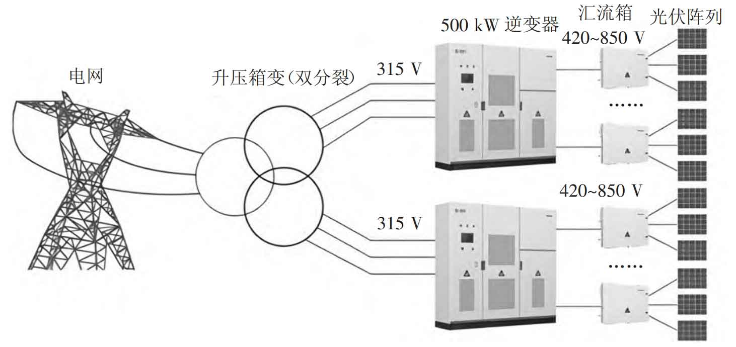
The centralized solar inverter photovoltaic system includes modules, combiner boxes, inverters, box transformers, and power grids. This scheme utilizes photovoltaic modules to generate electricity, and the combiner boxes are used to gather current, which is then transmitted to two 500 kW solar inverters. After passing through double split boxes, the system is connected to the grid. The topology of the centralized solar inverter photovoltaic system scheme is shown in Figure 1. Centralized solar inverters are usually installed at the maximum power point of the power plant to control the tracking of the maximum power point of the photovoltaic array and improve the operational efficiency of the photovoltaic system.
The implementation of the system scheme should pay attention to the following key points.
(1) Photovoltaic site selection, photovoltaic module selection, and tilt angle design. There are three main points: ① According to the requirements of flood control, fire protection, maintenance, etc., the photovoltaic field area is generally selected in plains or mountainous hills, avoiding seismic zones, downstream areas of rivers, etc. The connection distance between the substation and the photovoltaic field area should be shortened, and the incoming and outgoing lines should be adjusted appropriately. ② In the selection of photovoltaic unit modules, the most common photovoltaic modules currently are silicon based photovoltaic modules and thin film photovoltaic modules, among which silicon based photovoltaic modules are widely used The operation modes of photovoltaic arrays are diverse, and the investment, benefits, and difficulty of later maintenance vary depending on the operation mode. In the actual construction process, fixed tilt angle, adjustable tilt angle, and single axis and dual axis tracking methods are used for the angle design of photovoltaic modules. Among them, the cost of fixed tilt angle is lower, but the power generation efficiency is lower. The dual axis tracking method has the highest power generation efficiency, but the cost is higher. Therefore, the angle design of photovoltaic modules in most centralized solar inverter photovoltaic power plants is mainly based on adjustable tilt angles.
(2) Layout of photovoltaic modules. Determine the optimal tilt angle of the components based on the solar radiation in the construction area, and pay attention to the shading problem in the rear row when arranging the components to ensure a reasonable distance between the components. The layout of photovoltaic modules includes two types: horizontal and vertical. The horizontal layout is 4 pieces arranged from left to right, and the vertical layout is 2 pieces arranged from top to bottom.
(3) Design and installation of combiner box. For large and medium-sized grid connected photovoltaic power plants, 12 in 1 out and 16 in 1 out combiner boxes are selected based on the layout of photovoltaic modules. In practical applications, priority is given to selecting combiner boxes with multiple circuits. The combiner box has the ability to cut off fault current, and its incoming protection uses photovoltaic dedicated DC fuses, while the outgoing protection uses DC low-voltage molded case switches. Equip the combiner box with photovoltaic dedicated surge protectors to provide lightning protection; Install monitoring devices inside the combiner box to facilitate real-time monitoring of the DC current, total output current, and total output power of each incoming branch of the combiner box by staff. If any abnormalities are found in the incoming line, the monitoring device can promptly alarm.
The combiner box is installed and fixed on the component bracket using a hanging installation method, with the bottom height meeting relevant requirements. The inlet and outlet positions of the combiner box are kept at a certain distance from the bottom of the box, providing convenience for the construction of the inlet and outlet lines. Installing anti reflection diodes in the incoming circuits of each branch of the combiner box can improve the safety of the operation of the combiner box, although it may result in a certain loss of power generation. During the actual construction process of photovoltaic power plants, the installation of anti reflection diodes and the installation method to be adopted depend on the actual situation. For example, when the construction environment of photovoltaic power stations is high in humidity, temperature, or when DC cables are directly buried, it is recommended to install anti reflection diodes; If the construction environment of photovoltaic power plants is good and DC cables are laid along the bridge, it is recommended not to install anti reflection diodes.
3.2 Series solar inverter photovoltaic system scheme
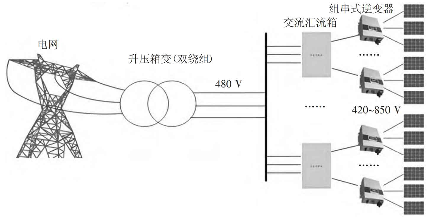
String solar inverter is a type of solar inverter that directly combines the power generated by photovoltaic modules into the solar inverter, converts it into AC power, and then concentrates it into the booster box through the combiner box for grid connection. The power of the string solar inverter ranges from 5 kW to 50 kW, and each solar inverter has multiple MPPTs. Therefore, the power generation of the string solar inverter photovoltaic system is relatively high. The topology of the string solar inverter photovoltaic system scheme is shown in Figure 2.
The implementation of a series solar inverter photovoltaic system scheme should pay attention to the following key points.
(1) Design of series and parallel numbers. In the design of series number, it is required that the minimum voltage of MPPT when the solar inverter is fully loaded ≤ the number of photovoltaic modules in series × The consideration voltage of a single component ≤ the highest input voltage of the inverter; In the design of parallel numbers, the number of components in parallel × Number of components in series × Component power × Capacity ratio ≤ the maximum input power of the inverter. The more photovoltaic modules are connected in series, the more combiner boxes or string solar inverters, as well as DC cables are needed. Therefore, under actual conditions, the maximum number of series connections should be selected. Considering the impact of photovoltaic module layout, wiring methods, and other factors on the cost of the support, a lower cost component series connection scheme should be selected.
For example, when the peak power of the photovoltaic module is 275 Wp, using 22 series connection methods, a single photovoltaic module can reach its maximum open circuit voltage. Considering the impact of on-site dust, line loss, and other factors on power generation, the input voltage value of the solar inverter is smaller than the maximum voltage range of the maximum power point tracking operation of the solar inverter. According to relevant requirements, the inclination angle of the component is 36 °.
(2) Component layout design. When the power of the solar inverter is 50 kW, 24 components can be arranged in a vertical 2 × 12 or Horizontal 4 × Mainly arranged in 12 rows, ensuring no obstruction between components and reducing power generation losses. From the perspective of component array area and cable cost, cable optimization design is carried out for two layout methods to reduce array area and cable cost.
(3) Design of photovoltaic subarray. Taking 275 Wp photovoltaic modules as an example, each string contains 22/24 modules, and every 9 strings are connected in parallel to a solar inverter, which is then merged into an AC combiner box. It is recommended to set the combiner box in the middle of the photovoltaic module array or near the roadside to facilitate the installation, maintenance, and transportation of the combiner box. Configure an intelligent communication box for each photovoltaic sub array, use an automation control module to maintain communication between the combiner box and the solar inverter, understand the operation status of both, and understand the operation status of the photovoltaic system.
3.3 Scheme of Distributed Solar Inverter Photovoltaic System
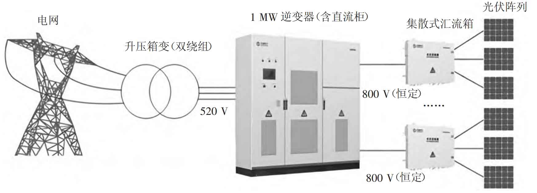
The topology of the distributed solar inverter photovoltaic system scheme is shown in Figure 3. The distributed solar inverter photovoltaic system scheme has the following advantages.
(1) Compared with the centralized solar inverter photovoltaic system scheme, the distributed solar inverter moves the MPPT forward to the combiner box and increases the number of combiner boxes, effectively reducing transmission losses.
(2) The distributed solar inverter photovoltaic system adopts distributed MPPT to reduce the loss of power generation caused by various mismatches.
Objectively, various factors such as the dispersion of components, the obstruction of the square array, and changes in the tilt angle of the bracket can all lead to mismatch losses. In the distributed solar inverter scheme, each intelligent MPPT controller has 4 or 8 MPPT control modules, and each MPPT control module is connected to 4 or 2 sets of strings. Compared with the centralized solar inverter photovoltaic system scheme where nearly 100 sets of strings are connected to 1 MPPT, the distributed solar inverter greatly reduces the parallel mismatch loss of the strings.
(3) The distributed solar inverter photovoltaic system can also achieve the effect of reducing AC and DC line losses. The intelligent MPPT control module (corresponding to the combiner box of the centralized solar inverter photovoltaic system scheme) has a voltage boosting function, which increases the long-distance (combiner box to inverter room) DC transmission voltage to around 800 V DC. Compared to the 600 V DC of the centralized solar inverter and the 480 V AC of the series solar inverter, the DC line loss of the distributed solar inverter photovoltaic system is significantly reduced. The AC output voltage of the distributed solar inverter photovoltaic system is correspondingly increased to around 500 V AC, and compared with the 315 V AC of the centralized solar inverter photovoltaic system, the AC line loss is also reduced.
(4) The overall efficiency of the distributed solar inverter photovoltaic system is high, and it has application advantages in large-scale distributed projects and mountain photovoltaic power stations. For example, a distributed photovoltaic power generation system converts the direct current transmitted by a photovoltaic array into alternating current with the same voltage, frequency, and phase as the grid using a solar inverter, and directly integrates the alternating current into the grid to achieve on-site utilization of power resources. Distributed solar inverters are generally installed on the side near the photovoltaic array. Compared with centralized solar inverters, they are more flexible in controlling the photovoltaic array MPPT and achieving maximum power point tracking of the photovoltaic array. However, they have higher technical requirements and construction costs.
(5) When designing small-scale photovoltaic power generation projects, the distributed solar inverter photovoltaic system requires a small power output of the solar inverter. The distributed solar inverter photovoltaic system should achieve “instant use” when connected to the grid, usually using a two-stage grid connection method to achieve the above requirements: the first level is that the electricity generated by the photovoltaic array directly enters the grid, The second stage is to convert direct current into alternating current through a solar inverter and send it to the power grid. In the second stage, the dual anti parallel inverter technology is used to avoid harmonic problems and reduce the harmonic content in the grid connected current. In addition, in order to ensure the stable operation of solar inverters, it is necessary to choose high-quality components.
4. Conclusion
The design of photovoltaic system schemes based on different solar inverters requires comprehensive consideration of the characteristics of the photovoltaic power station construction area, economic costs, and relevant technologies required for inverters. On the basis of improving the power generation capacity and efficiency of photovoltaic systems, appropriate solar inverters should be selected for photovoltaic system design, emphasizing the layout, angle design, and distance between photovoltaic modules to improve the utilization of renewable resources and ensure the stability and safety of power supply.