
With the development of the economy and social progress, conventional energy is facing the danger of depletion. Finding and utilizing renewable energy has become an urgent issue facing humanity. Many types of renewable energy, such as solar, wind, hydro, and tidal energy, have reached the level of large-scale utilization. Among them, solar energy, with its unique advantages such as unlimited energy storage, widespread existence, and available cleanliness, will inevitably be valued and used by more people. In power electronics systems, we use inverters to convert the energy of solar energy into AC loads for our ordinary users. However, solar energy cannot be abundant every day, and the various batteries currently used consume more conventional energy. Therefore, we propose the concept of a bidirectional inverter. The bidirectional inverter system proposed in this article can enable energy to flow between the DC side and the AC power grid, ensuring that the DC side voltage can be stable within a certain range.
1. System architecture
As shown in Figure 1, it is a block diagram of the solar bidirectional inverter proposed in this article. It can be seen that the system is roughly composed of two circuit architectures: the front stage is a Boost boost circuit with maximum power tracking function, and the rear stage is a DC to AC conversion circuit composed of a full bridge bidirectional inverter. The DC power output from the solar photovoltaic panel is first boosted to the set voltage through the maximum power tracking of the previous stage, and then connected in parallel to the grid at the other end through a bidirectional inverter. The system has two operating modes: mains parallel mode and power factor correction:
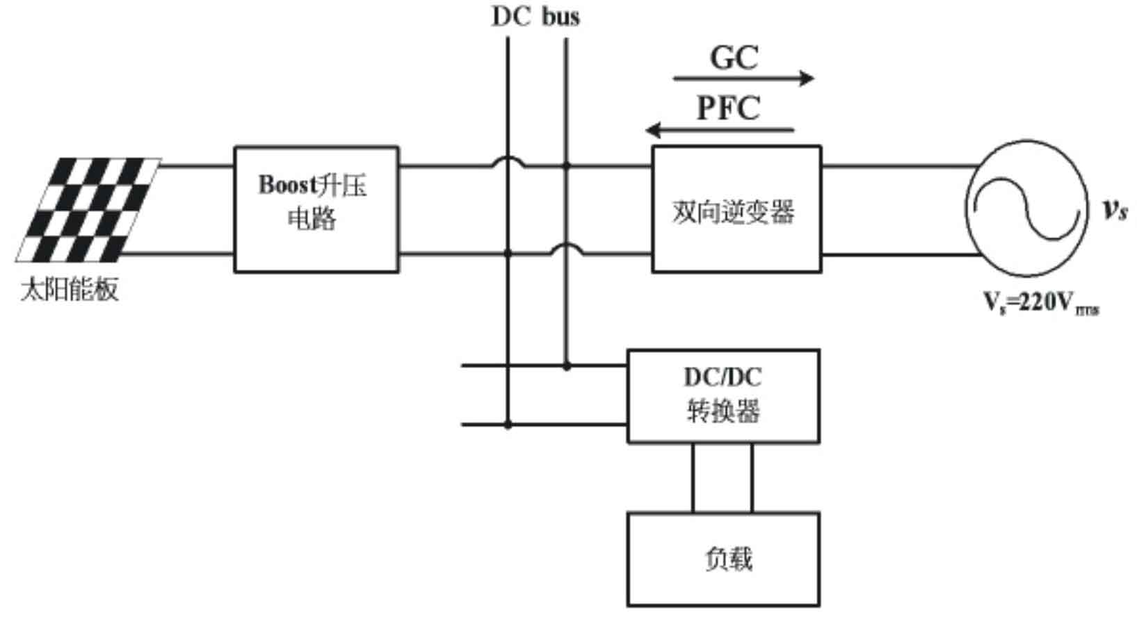
(1) Mains parallel mode (GC)
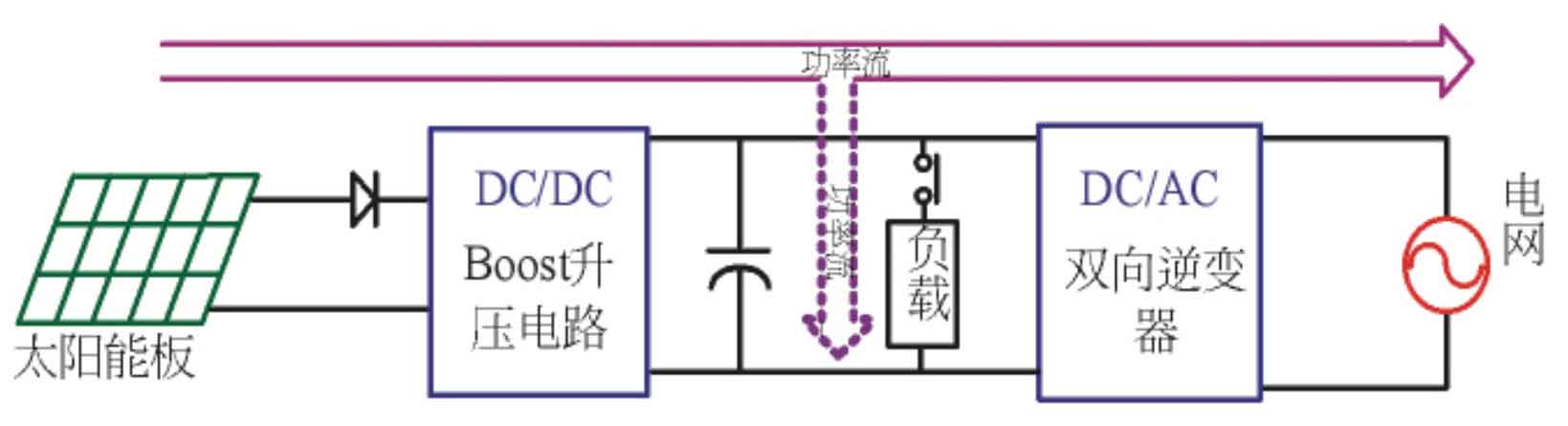
As shown in Figure 2, it shows the power flow of the system in the parallel mode of mains power supply. When the output power of the solar panel is higher than the required power of the load, the bidirectional inverter operates in the parallel mode of the mains, feeding the remaining energy into the power grid.
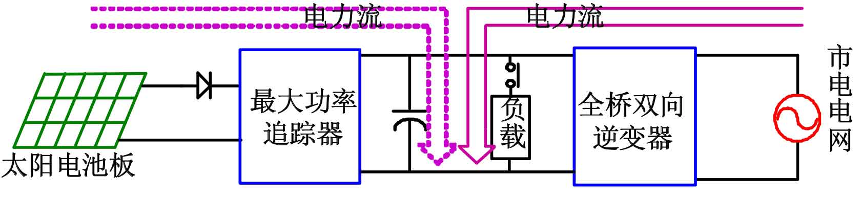
(2) Power Factor Correction Mode (PFC)
As shown in Figure 3, the power flow of the system in power factor correction mode is shown. When the DC side voltage drops below 360 V, solar energy is insufficient to provide the required power for the load. The bidirectional converter switches to power factor correction mode to convert the grid energy into DC supply load to achieve stable DC side supply. Different DC/DC converters are used to supply different DC loads. From this, it can be seen that the biggest advantage of this system is that it does not require the use of energy storage devices such as battery modules, greatly reducing system volume, quality, and cost, which is more conducive to protecting the environment and improving the efficiency of the inverter.
1.1 Maximum power tracker
The main circuit of the maximum power tracker is actually a Boost boost circuit. The input is a DC voltage source, and the output is also a DC voltage source. The internal components include power switches, fast diodes, energy storage inductors, and DC side energy storage capacitors. Its working principle is that when the power switch is turned on, the input voltage begins to charge the inductor and store energy in it, at which point the inductor current gradually increases. When the power switch is cut off, the energy stored by the inductor accumulates with the input power energy, and is discharged to the load through a fast diode, so the output voltage will be higher than the input voltage. The function of maximum power tracking is to rely on the microcontroller to capture the voltage and current output from the solar panel, and output PWM waves with different duty cycles based on disturbance observation method. The switch is determined by the high and low levels of the PWM wave to determine its conduction and cutoff.
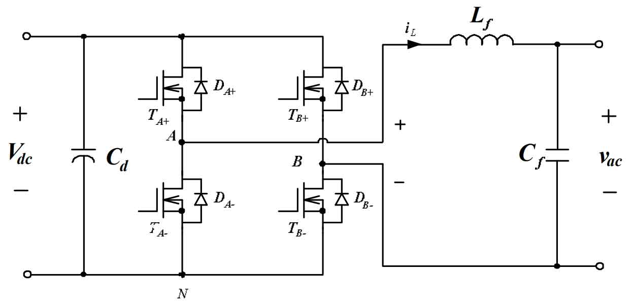
1.2 Full bridge bidirectional inverter
As shown in Figure 4, the full bridge inverter is composed of four power switches, filtering inductors and capacitors, and DC side energy storage capacitors. The full bridge inverter can be divided into A and B arm switches. The control signals of the same arm switch are complementary to each other and have blank time to avoid short circuits caused by the simultaneous conduction of the upper and lower arms. The DC side voltage stabilizing capacitor is designed to provide a stable voltage supply to the load. The main function of a full bridge inverter is to generate high-frequency modulation signals by controlling the switching of four power switches, and then filter them through the next level of filtering inductance and capacitance, leaving the required 50 Hz low-frequency AC signal. The control method for power switch switching is to use Sinusoidal Pulse Width Modulation (SPWM) and high-frequency switching to reduce switch losses and the volume of the subsequent filtering circuit. The microcontroller adopts predictive current control method, which controls the rise and fall of the output inductor Lf current by calculating the duty cycle of the input voltage of the inductor Lf.
2. Simulation analysis
In order to verify the feasibility of the proposed single-phase bidirectional inverter, this paper designs and proposes a circuit topology structure based on dsPIC, and its specifications are shown in Table 1.
| Specifications | Value |
| DC side voltage/V | 340-390 |
| Grid voltage | 220V/50Hz |
| Front switch frequency/KHz | 50 |
| Rear stage switch frequency/KHz | 20 |
| Output power/Kw | 1 |
| Element | Value |
| Output filter inductance/mH | 5 |
| Output filter capacitor/µF | 5 |
| Microcontroller | DsPIC30F4011 |
This article uses PISM circuit simulation software to verify the feasibility of the entire system, which includes two working modes of the system: parallel power supply mode and power factor correction mode.
2.1 Single mode
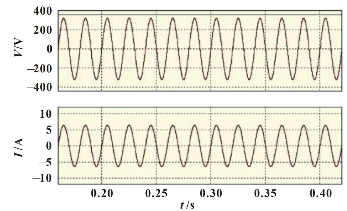
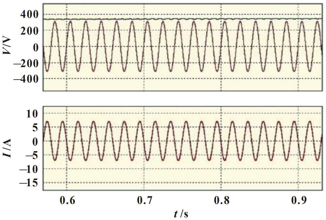
Figure 5 shows the DC side voltage waveform, output voltage, and output current waveform of a bidirectional inverter operating in parallel mode with mains power. In this mode, the bidirectional converter will supply the remaining energy after the load and collapse into the mains terminal. So it can be seen that the output current of the inverter is in phase with the output voltage, and the frequency is both 50 Hz, meeting the design requirements. In PFC mode, due to insufficient solar energy to supply the load, the main function of the bidirectional converter is to provide energy conversion from the mains to the load. Figure 6 shows the line voltage waveform, inverter output current waveform, and DC side voltage waveform of the inverter operating in power factor correction mode. In this mode, the output current of the inverter is in phase with the line voltage, and the DC side voltage can be stable within the calibration range.
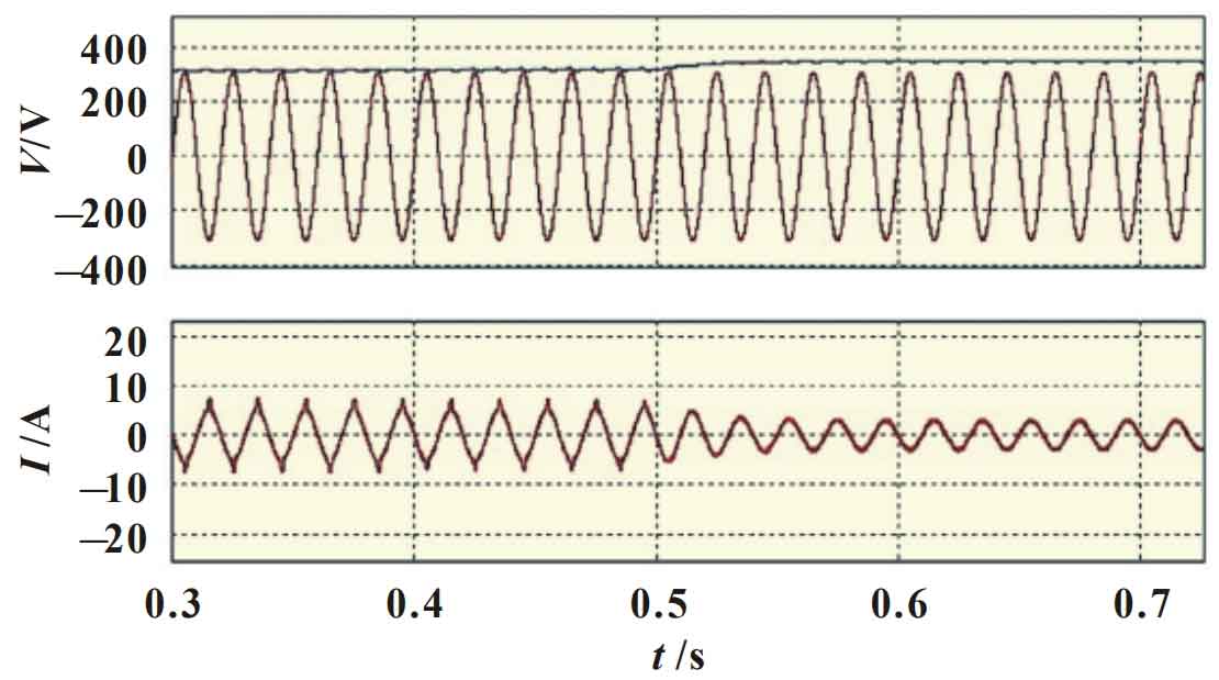
2.2 Mode Conversion
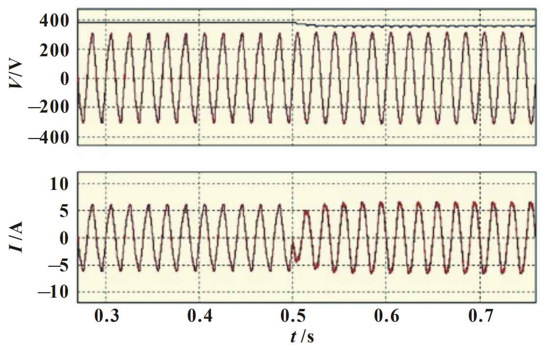
Figures 7 and 8 show the transition of the bidirectional converter operation mode between GC mode and PFC mode. In Figure 8, the operation mode changes from GC mode to PFC mode. It can be seen that the DC side voltage has decreased, but it can still remain stable within the calibration range. The output current of the inverter changes from being in phase with the line voltage to being in phase with the line voltage. Similarly, it can be seen that when the operating mode is switched from PFC to GC, the output current of the inverter changes from being in phase with the line voltage to being in phase with the line voltage. From this, it can be verified that the inverter can achieve perfect conversion between the two modes.
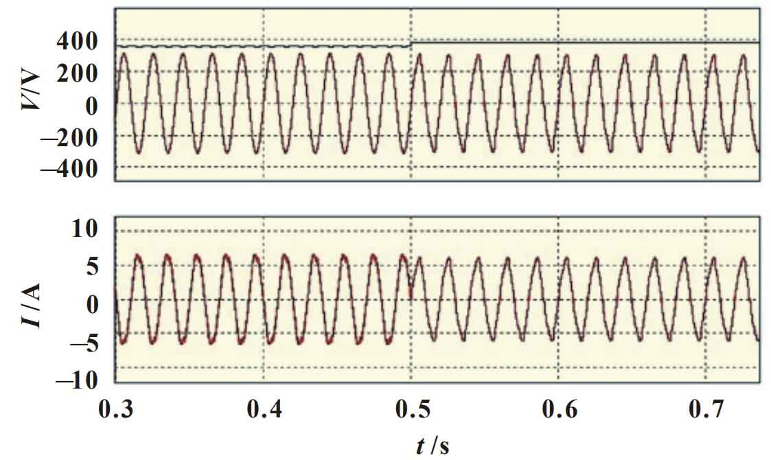
2.3 Load changes
Simulated the load transformation of the inverter operating in PFC mode. When the load changes from light to heavy, the output current of the inverter decreases. The microcontroller senses this and adjusts the duty cycle of the full bridge switch, allowing more mains energy to pass through the inverter and collapse into the DC side load terminal, resulting in an increase in the DC side voltage (Figure 9).
3. Conclusion
A solar power supply system with bidirectional inverters has been proposed, which can operate in two modes: mains parallel mode and power factor correction. The characteristic of this system is that it only uses a microcontroller chip and does not require energy storage devices such as batteries to fully utilize solar energy. This not only reduces costs, but also maximizes environmental protection. The circuit simulation results can confirm the feasibility of the proposed system.