
Energy is the foundation of social development and human progress. With the rapid development of economy and technology, the demand for energy in industrialized societies is increasing, which promotes the rapid development of the power industry, leading to excessive consumption of conventional energy and causing a series of problems such as global warming and environmental pollution. In response to the energy crisis and environmental pollution, renewable energy sources such as hydropower, tidal energy, biomass energy, wind energy, and solar energy have received attention and attention from countries around the world, especially wind and solar energy, which have become the mainstream direction of new energy development. Taking wind power as an example, in 2019, the national wind power added 25.74 million kilowatts of grid connected installed capacity, with a cumulative installed capacity of 210 million kilowatts. Wind power installation accounted for 10.4% of the total power generation installed capacity, and the annual wind power generation reached 405.7 billion kilowatt hours, surpassing 400 billion kilowatt hours for the first time, accounting for 5.5% of the total power generation.
With the development and application of various large-scale renewable energy sources in China, new energy power stations and distributed new energy generation equipment are widely connected to the power grid. Medium voltage and large capacity power electronic converters are key components of new energy generation and core interface equipment in the new generation power grid. They have become key supporting technologies for significantly improving future power grid transmission capacity, stability, regulation ability, and power quality. Although traditional two-level and three-level converters can further improve voltage and power levels through phase-shifting transformers, device series connection, and parallel connection of power units, they also bring a series of problems such as complex design, increased volume, expensive cost, high dynamic voltage and current sharing requirements, and low reliability. The use of wide bandgap semiconductor power devices based on SiC and GaN can also effectively improve the voltage and power levels of traditional converters. However, at the current level of production technology, there is a contradiction between the switching frequency and power capacity of power electronic devices. Usually, the larger the power capacity, the lower the switching frequency. However, reducing the switching frequency can lead to issues such as decreased output power quality and increased electromagnetic interference, making it difficult to meet the requirements and standards of relevant applications. In the absence of fundamental breakthroughs in new power semiconductor devices, conducting research on the topology and control technology of medium and high voltage power electronic converters has become an effective way to achieve high-performance and high-power power conversion.
The emergence of Modular Multilevel Converter (MMC) has opened up new ideas for the implementation of medium to high voltage and high capacity power conversion technology. This power conversion technology connects multiple submodule converters in series, and the power level and voltage level can be flexibly adjusted by changing the number of submodules. Modular structure is suitable for industrial design and production, and it is also easy to achieve redundant protection, improving system reliability. In addition, the output voltage is a multi-level structure, which reduces the requirements for filters and can be directly connected to the medium and high voltage power grid without the use of power frequency transformers, effectively reducing the cost and volume of the system. Due to the above advantages, modular multi-level converters have broad application prospects in the field of medium, high voltage, and large capacity. In addition to being applied in renewable energy generation systems, they are also used in various occasions such as variable frequency drive, DC transmission, reactive power compensation, etc. Taking the offshore DC wind power transmission system based on MMC as an example, its typical structure is shown in Figure 1. The output power of each wind turbine is collected through the wind farm collection system, connected to the wind farm side MMC through a step-up transformer, and then transmitted through the submarine DC cable. Finally, it is integrated into the grid through the grid side MMC.
Compared to traditional fossil fuels, renewable energy has characteristics such as abundant resources, sustainability, efficiency, and cleanliness. However, it also has disadvantages such as strong randomness, large fluctuations, and discontinuity. When large-scale grid connection occurs, it has a significant impact on the power grid, affects the stability of the power system, and even causes local grid paralysis. Therefore, renewable energy generation systems are often equipped with a battery energy storage system (BESS) to smooth power fluctuations and improve system stability.
In the offshore DC wind power system shown in Figure 1, the battery energy storage unit is connected to the wind farm through the Power Conversion System (PCS). In addition to suppressing power fluctuations, it can also improve the damping of the wind turbine and compensate for the virtual inertia of the system. However, ensuring the safe, reliable, and efficient operation of large capacity battery energy storage systems is still a challenging task at present. When using an energy storage system based on two-level and three-level converters, the battery energy storage unit needs to undergo a large number of series and parallel connections to improve energy storage capacity, which brings various problems such as low reliability and complex energy management. The use of Cascaded H-bridge (CHB) energy storage systems can effectively solve the problems of low reliability and complex energy management in large capacity energy storage systems.
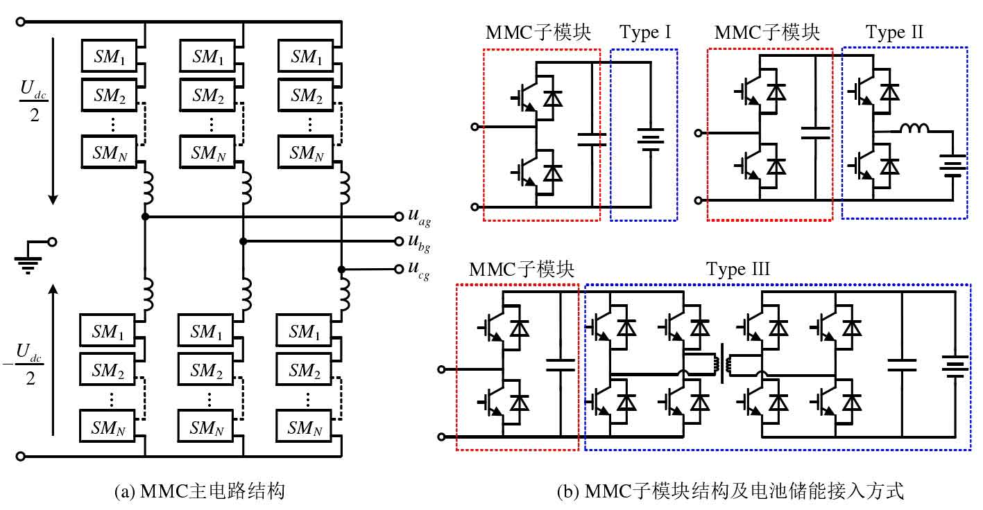
As shown in Figure 2, while MMC performs AC/DC power conversion, its submodules can serve as the interface for the battery energy storage unit, achieving modular access to the battery energy storage unit, forming a modular multilevel converter with integrated battery energy storage system (MMC BESS) for energy storage. According to the needs of different application scenarios, battery energy storage units can be connected to MMC submodules in different ways. Figure 2 (b) shows three commonly used connection methods. In Type I, the battery is directly connected in parallel with the MMC submodule capacitor to achieve higher efficiency and lower cost. However, low-frequency current pulsation can flow into the battery, affecting the lifespan of the battery unit. Moreover, the voltage changes of the energy storage unit during the charging and discharging process can also affect the normal operation of the system. The battery cells in Type II are connected to the MMC submodule through non isolated DC/DC, which can avoid low-frequency pulsating current flowing into the battery and provide new control freedom for the system, increasing the flexibility of system control. The battery in Type III is connected to the MMC submodule through an isolated DC/DC converter, suitable for occasions with electrical isolation requirements. From the perspective of functionality and practicality, it is an ideal integration method for batteries to be connected to MMC submodules through the primary DC/DC link, which is conducive to fully utilizing the role of battery energy storage systems. This article only considers this battery connection method.
The energy storage method of directly integrating the battery energy storage unit into MMC does not require the configuration of an independent PCS for the battery energy storage unit, which is conducive to system integration and coordinated control, and can fully utilize the role of the battery energy storage system. More importantly, the modular access method of battery energy storage units also brings the following advantages:
1) This reduces the voltage level of the battery pack, avoids the series and parallel connection of a large number of energy storage units, and improves the reliability and safety of the energy storage system.
2) The configuration method of energy storage units is more flexible, and each submodule can be configured with different types, voltage levels, and capacities of energy storage units, or even only some submodules can be configured with energy storage units.
3) Each submodule can be independently controlled, and the State of Charge (SOC) balance of the battery energy storage unit can be achieved without the need for a complex energy management system.
It can be seen that modular multi-level converters can not only meet the requirements of renewable energy generation systems for medium to high voltage and high capacity power converters, but also provide interfaces for the connection of battery energy storage systems, forming an AC/DC interconnection interface with energy storage function. This structure is more conducive to the collaborative control of system integration and AC/DC power transmission, and can fully utilize the role of energy storage systems, which is of great significance for solving problems such as renewable energy generation grid connection. Based on the above reasons, in-depth research will be conducted on modular multi-level converters and their applications in battery energy storage systems will be explored.
1. Energy storage modular multi-level converter
1.1 Power transmission mode
The Modular Multilevel Converter with Integrated Battery Energy Storage System has three power ports: AC, DC, and battery. Its power transmission is different from the original MMC. Power can only be transmitted between any two power ports or simultaneously between the three power ports, and there are multiple power transmission modes as shown in Figure 3. In Mode I, power is only transmitted between the DC and AC ports, and the power transmission of Modular Multilevel Converter with Integrated Battery Energy Storage System is the same as that of ordinary MMC. In modes II and III, power is only transmitted between the battery and the DC port or between the battery and the AC port, and the Modular Multilevel Converter with Integrated Battery Energy Storage System, which operates only as PCS, operates in these two modes. In Mode IV, the DC, AC, and battery ports are all involved in power transmission, which is the most common power transmission mode for Modular Multilevel Converter with Integrated Battery Energy Storage System.
For battery energy storage systems, maintaining the SOC balance of each battery energy storage unit is an important goal. Unbalanced SOC can cause overcharging and discharging of some battery energy storage units, leading to a decrease in the actual capacity of the energy storage system. SOC represents the percentage of remaining storage energy in the rated storage energy of the energy storage unit. Obviously, for energy storage units with larger SOC, their discharge power should be increased or their charging power should be reduced. For energy storage units with smaller SOC, their discharge power should be reduced or their charging power should be increased in order to make the SOC of each energy storage unit tend to be the same. Therefore, during the SOC equalization process, the battery power injected into each submodule is not equal, resulting in internal power transmission between the phases, bridge arms, and submodules of Modular Multilevel Converter with Integrated Battery Energy Storage System as shown in Figure 4. Figure 4 (a) shows the phase power transmission. For a balanced three-phase AC output voltage, when the AC output power Pkac of each phase is equal and the injected battery power (Pbku+Pbkl) of each phase is not equal, it can be inferred from the power balance that the DC power Pkdc borne by each phase is not the same. Figure 4 (b) shows the power transmission between the bridge arms. When the upper bridge arm battery power Pbku and the lower bridge arm battery power Pbkl are not equal, there is power transmission Pk between the upper and lower bridge arms Δ To maintain the balance of bridge arm power, this power transmission is achieved by injecting fundamental frequency components into the circulation. Within the bridge arm, the battery power Pbkji of each submodule must be equal to the MMC side power Pkji to maintain the voltage balance of the submodule capacitors. So when the battery power of the submodules is unequal, the power Pkji absorbed by the submodules from the MMC side needs to be adjusted accordingly to match the battery power. At this time, the power transmission between the submodules is shown in Figure 1-4 (c).
1.2 Control strategy
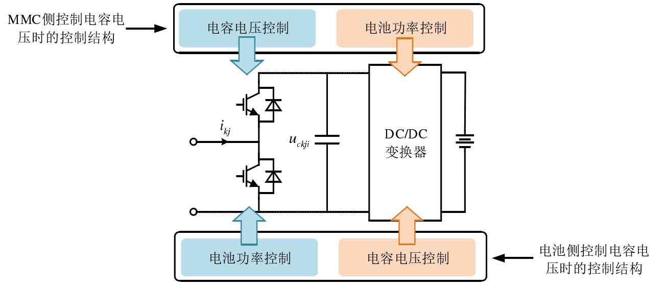
The battery energy storage unit is connected to the submodule through the DC/DC link, providing a new degree of control freedom for MMC. The submodule control has two structures shown in Figure 5, and the capacitor voltage can maintain the control structure in the original MMC, It can also be directly controlled by the battery side DC/DC link The former does not change the control structure of MMC, and the battery side DC/DC link only needs to control the power of the battery energy storage unit. The operation between the MMC side and the battery side can be considered independent of each other, and even if a part of the battery energy storage unit is removed, it will not directly affect the operation of MMC, so it has high reliability and flexibility. The latter does not need to balance the capacitor voltage of the submodule on the MMC side, but the battery power depends on the MMC side Conducting indirect control can lead to complex SOC balancing issues. In addition, the operation of the MMC side relies on the energy storage side, requiring all submodules to be equipped with energy storage units and in normal operation, which leads to poor flexibility and low reliability. Based on the above reasons, this article only considers the control structure of the MMC side control capacitor voltage.
Taking Modular Multilevel Converter with Integrated Battery Energy Storage System for controlling grid connected power as an example, the specific control structure is shown in Figure 6. The introduction of a battery energy storage system does not change the control structure of the original MMC, only equivalent to connecting a constant power load to each submode. The MMC side control can be divided into three parts: AC circuit control, circulating current circuit control, and submodule capacitor voltage balance control. The AC circuit control directly follows the control structure of a two-level converter, obtaining active current command * gdi and reactive current command * gqi based on active power command * acP and reactive power command * acQ, and then synchronously rotating the coordinate system in dq (or αβ Under the stationary coordinate system, the corresponding closed-loop control is carried out on the current to generate the instruction value * kdiffu for the differential mode component of the bridge arm voltage.
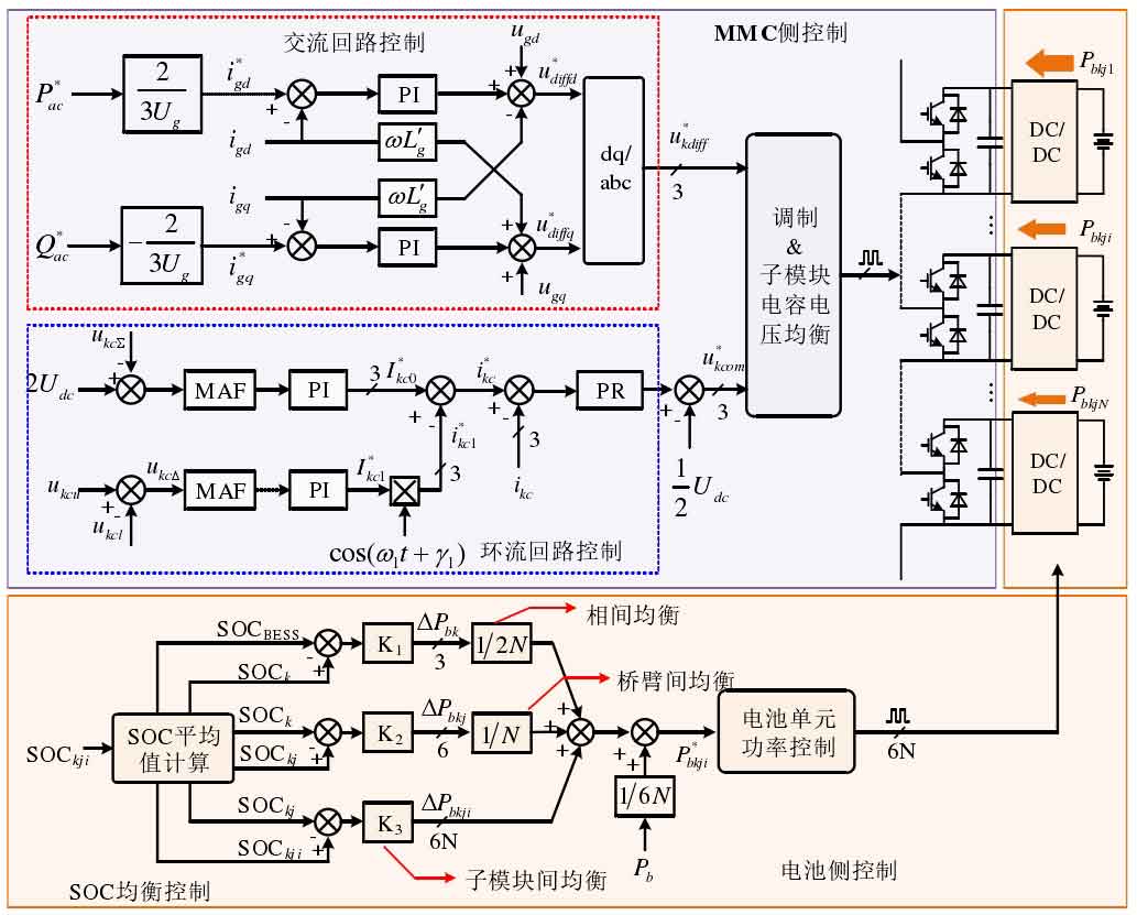
The loop control consists of three parts: phase capacitor voltage balance control, bridge arm capacitor voltage balance control, and loop control. The goal of phase capacitor voltage balance control is to maintain a total capacitor voltage of 2 Udc for one phase, and the controller outputs the command value * kc0I as the DC component in the circulating current. The goal of capacitor voltage balance control between bridge arms is to maintain the balance of capacitor voltage between upper and lower bridge arms, i.e. kcu Δ=0, and the controller outputs the command value * kc1i for adjusting the fundamental frequency circulating current. After obtaining the circulating current command * kci through the balanced control of capacitor voltage between phases and bridge arms, a Proportional Resonant (PR) controller is used to closed-loop control the circulating current, generating the command value * kcou of the common mode component of the bridge arm voltage. The sub module capacitor voltage balance control maintains capacitor voltage balance by distributing the switch signals of the sub modules. The control method is closely related to the modulation strategy and will be emphasized in subsequent chapters, which will not be repeated here.
The battery side DC/DC link is mainly responsible for controlling the charging and discharging power of the battery, and the key is how to obtain the sub module battery power command * bkjiP based on SOC balance control. SOC balancing control is divided into three layers: inter phase, inter bridge arm, and inter sub module balancing control. When the average value SOCk of a phase submodule SOC is less than the average value SOCBES of the energy storage system SOC, the power bk Δ P is added to the power command value of the phase battery to reduce the output power of the phase battery. Conversely, the output power of the phase battery is increased, and the SOC balance control between the bridge arms and submodules also adopts the same control structure. The controller parameters K1, K2, and K3 can adjust the SOC equalization speed. The larger the controller parameters, the faster the SOC equalization speed. In addition, when each submodule is configured with energy storage units of different capacities, it is necessary to further adjust the charging and discharging power of the energy storage unit based on its actual capacity to ensure the convergence of SOC.
In summary, the introduction of a battery energy storage system is equivalent to incorporating a constant power load into the MMC submodule, without changing the operating principle and control structure of the MMC itself. But the battery energy storage system will change the power transmission mode of MMC, and its SOC balance control will also affect the power balance between phases, bridge arms, and sub modules, thereby affecting the steady-state characteristics of the system and capacitor voltage balance characteristics. Therefore, research on the Modular Multilevel Converter with Integrated Battery Energy Storage System should be based on MMC, and then focus on new issues introduced by battery energy storage systems.
2. Key Technologies and Research Status
So far, significant progress has been made in the research of MMC systems in academia and industry, as well as research on their application in battery energy storage systems. This section focuses on the key issues of MMC and its application in battery energy storage systems, and is mainly divided into two parts. The first part is the key issues of the MMC system itself, mainly focusing on its operational characteristics analysis and mathematical model. It is crucial for designing control strategies, tuning controller parameters, and optimizing system performance; The second part is the key issues introduced into the battery energy storage system, mainly related to the voltage balance and pulsation suppression of the sub module capacitor. The following summarizes the research status and existing problems of each key technology at home and abroad.
2.1 Operating characteristics and equivalent circuit model of AC port
The MMC port model, also known as the input output model, has the advantages of simplicity and intuition, and is an important basis for analyzing system output characteristics, designing control strategies, and optimizing system output performance. Due to the special circuit structure of MMC, in addition to the DC and fundamental frequency components related to power transmission, there are also various harmonic components in each variable. This affects the operating characteristics of the MMC AC port, which is much more complex than traditional two-level converters.
There is a relationship between the variables in the MMC system as shown in Figure 7 (a). Taking the bridge arm as an example, in addition to the DC component, there are also pulsating components on the sub module capacitor voltage ckuiu, mainly based on the fundamental frequency and secondary frequency. However, when calculating the modulation signal kuiS of the submodule, direct modulation is often used, which ignores the voltage ripple component of the submodule capacitor and directly replaces the actual value with the reference value of the capacitor voltage. Affected by this, the voltage ripple component of the capacitor is modulated to generate various frequencies of voltage on the sub module port voltage kuiu, such as DC, fundamental frequency, secondary, and tertiary, and then affects the bridge arm current k through the main circuit loop
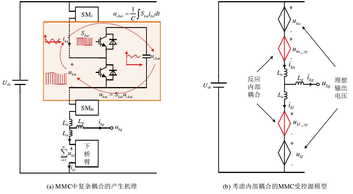
UI. On the one hand, the bridge arm current is controlled by the circulating current circuit and the AC circuit, which affect the modulation signal kuiS of the submodule. On the other hand, after modulation, it again affects the capacitor voltage. This mutual circulation creates a complex internal coupling relationship between the capacitor voltage, bridge arm current, and modulation signal. When considering the influence of internal coupling, one phase of MMC can be represented by a controlled source model as shown in Figure 7 (b). The output voltage of the bridge arm consists of two parts. One part is the ideal output voltage kuu of the bridge arm, which is the output voltage without considering internal coupling; The other part is the output voltage k of the internal coupling reaction
U_ RPU, obviously it will affect the operational characteristics of the MMC communication port.
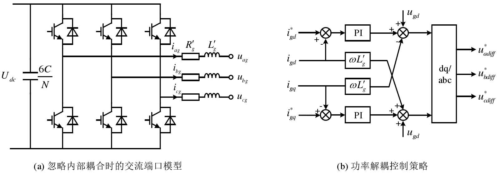
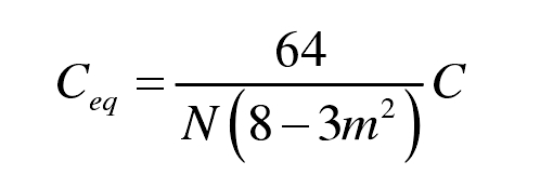
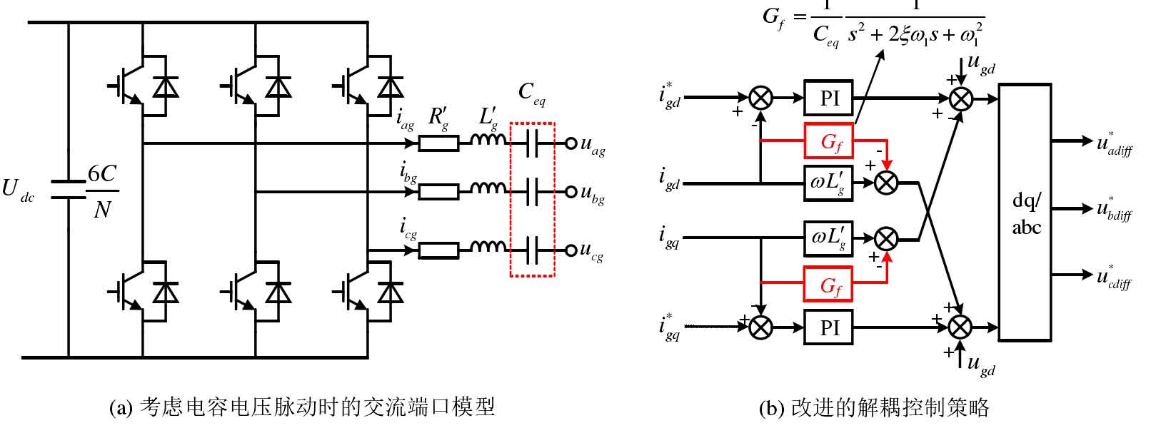
Completely ignoring the influence of internal coupling, i.e. ignoring the voltage ku in Figure 7 (b)_ RPU and Kl_ RPU, which equates the MMC AC port to a two-level converter as shown in Figure 8 (a), is currently the most widely used AC port model. Then, the control strategy of the two-level converter can be directly adopted to obtain the power decoupling control strategy based on the dq synchronous rotating coordinate system as shown in Figure 8 (b). Obviously, equating MMC to a two-level converter can greatly reduce the difficulty of analyzing MMC output characteristics and designing control strategies, making it convenient for practical engineering applications. However, this simplified model ignores the influence of internal coupling and cannot accurately describe the operational characteristics of the AC port, and the control strategy based on this cannot achieve good control performance. In order to accurately describe the operating characteristics of the MMC AC port, a high-performance control strategy was designed, taking into account the influence of capacitor voltage ripple components. Ignoring the loop control, the influence of internal coupling was reflected by serializing capacitor Ceq at the AC port of the two-level converter. The equivalent circuit model shown in Figure 9 (a) was obtained, and the specific expression of capacitor Ceq was:
In the formula, C is the submodule capacitance, N is the number of bridge arm submodules, and m is the modulation ratio.
Through steady-state and dynamic simulations, it has been shown that the AC port model of the series connected capacitor Ceq is more accurate than the two-level converter model. However, due to the neglect of the influence of circulation loop control and the fact that the model is based on steady-state analysis, it is essentially a steady-state model, and there are still significant differences in its dynamic characteristics compared to MMC. Based on this equivalent circuit model, a decoupling control strategy was designed as shown in Figure 9 (b), with the decoupling term Gf taking into account the influence of the equivalent capacitance Ceq:
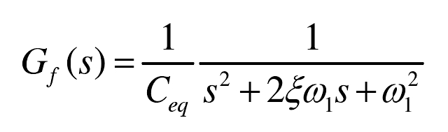
In the equation, ξ Is the damping coefficient, by changing the damping coefficient ξ Adjust the power decoupling control effect while suppressing the oscillation problem introduced by the decoupling term Gf. However, due to the lack of accurate models, the decoupling control effect is not ideal, and the design of damping coefficients still needs to be studied.
In summary, establishing an AC port equivalent circuit model that accurately reflects the internal coupling effect is the key to studying the output characteristics of the system and designing high-performance control strategies, which is of great significance for the engineering application of MMC.
2.2 Analysis of internal steady-state and dynamic characteristics
In addition to the output ports, there are also multiple variables and control loops within the MMC system. Obtaining the interaction patterns between internal variables and control loops, ensuring good steady-state and dynamic characteristics of internal variables, is a prerequisite for maintaining reliable and efficient system operation. In addition, when MMC is applied to battery energy storage systems, higher requirements are placed on the steady-state and dynamic performance of internal variables such as capacitor voltage and circulating current. However, there is a complex coupling relationship within the MMC system as shown in Figure 7 (a). How to construct an MMC mathematical model that can accurately describe the complex coupling relationship and conduct steady-state and dynamic analysis on it has always been a research hotspot and difficulty in the MMC system. The current research work related to the stable and dynamic characteristics of MMC. The following will be introduced from two aspects: steady state and dynamic.
(1) Steady state characteristic analysis
Steady state analysis in MMC usually refers to obtaining the steady-state values of various variables under certain input and output constraints. Its purpose is to provide a reference basis for the economic and superiority evaluation of main circuit parameter design and engineering design. In addition, it can also obtain the interaction laws between various variables and optimize the steady-state performance of the system based on this.

The analysis method based on the MMC time-domain model is convenient for describing the working principle of the system and is currently the most commonly used steady-state analysis method. The typical time-domain analysis process is shown in Figure 10, where the switching functions Sku and Skl of the upper and lower bridge arms are regarded as input variables, the circulating current ikc and AC output current ikg are regarded as output variables, and the bridge arm capacitor voltage ucku, uckl, and the bridge arm output voltage uku, ukl are intermediate process variables, which can be calculated based on the switching function, circulating current, and output current. The bridge arm switch function contains multiple frequency components, and its general expression is:
Among them, mk0 and mkc2 θ Kc2 is used to control the direct current component and the second harmonic component in the circulation, respectively; Mk1 θ K1 is used to control the output power (voltage) of the AC port. In addition, the switching function can also include components of other frequencies to achieve other control objectives such as specific secondary circulation injection.
The steady-state time-domain analysis method first obtains the capacitor voltage and output voltage of the bridge arm based on the switch function and bridge arm current. Then, the MMC circuit is divided into sub circuits with different frequencies, such as AC loop, DC loop, and secondary loop. Finally, establish a matrix equation between the input and output variables based on the equations of each circuit, and solve the matrix equation to obtain the steady-state values of each variable. The open-loop time-domain analysis method does not consider the influence of the control system and directly gives the bridge arm switch function in the formula. Ignoring the quadratic components in the switching function, the interaction between circulating current and capacitor voltage was studied, and a matrix equation containing all circulating current frequency components was established. Considering that the harmonic components above the second order in the circulation are relatively small, only the second order component in the circulation is considered, and a more concise expression for the second order circulation is given. The focus was on studying the influence of the secondary component of the switching function on steady-state performance such as capacitor voltage ripple, bridge arm current peak, and bridge arm current effective value. The system performance under different secondary circulation control was evaluated, providing an important basis for optimizing the design of main circuit parameters.
The results of open-loop analysis are generally in analytical form, which is convenient for summarizing the interaction laws between various variables. However, due to the neglect of the influence of the control system, the accuracy of the analysis results needs to be improved. To this end, the influence of the control system was considered, and all components of the switch function were set as unknown variables. The Newton Raphson method was used to solve the input-output matrix equation, thereby obtaining accurate switch functions and improving the accuracy of steady-state analysis. This method is called closed-loop time-domain analysis method.
On this basis, the third harmonic component in the switching function is considered, further improving the accuracy of steady-state analysis. However, both open-loop and closed-loop time-domain analysis methods involve a large amount of trigonometric function calculations in the process of constructing input-output matrix equations, and the complexity increases rapidly with the increase of harmonic frequency.
The steady-state phasor analysis method converts sinusoidal alternating current into phasors, represented by active and reactive components, thereby avoiding the complex calculation and solution process of trigonometric functions in time-domain analysis. This method can not only be used for designing main circuit parameters, but also for steady-state time-domain simulation, system power transmission analysis, and so on. However, due to the fact that MMC variables contain multiple frequencies and require rotating coordinate systems with multiple frequencies such as fundamental, secondary, and tertiary to represent each variable as active and reactive components, there is still a problem of complex analysis processes.
(2) Dynamic characteristic analysis
The dynamic characteristics analysis methods of MMC are mainly divided into two categories: the first type directly adopts the analysis methods of nonlinear systems; The second type linearizes nonlinear systems and uses classical linear system analysis methods. Lyapunov theory and Floquet theory are typical nonlinear system analysis methods and are also used in MMC systems. Reference based on Lyapunov theory pointed out that MMC has the characteristic of self stability under open-loop control, while reference [74] studied the stability of the system under closed-loop control. Linearize the periodic time-varying model of MMC and directly determine the stability of the system using Floquet theory
Sex. However, nonlinear analysis methods are difficult to locate the factors that cause system instability, making it difficult to guide the design of controller parameters for multiple loops in MMC.
The analysis method based on linear systems transforms time-varying models into time-invariant models, and after small signal linearization, classical linear system methods such as eigenvalue analysis and Nyquist stability criteria are used for analysis. According to the different methods of transforming time-varying models into time-invariant models, there are mainly simplified model analysis methods, multi harmonic linearization analysis methods, dynamic phasor model analysis methods, and harmonic state space theory (HSS) analysis methods. The simplified model analysis method only considers the frequency components related to power transmission, ignoring the harmonic components related to reactive power in power transmission, and is mainly used for simplified design of controller parameters. Based on this analysis method, design
The parameters of each controller in the circulation loop control were designed, and the controller parameters on the AC output side were designed in reference [76]. The multi harmonic linearization analysis method is developed from the traditional harmonic linearization analysis method, which reflects the multi frequency coupling characteristics of MMC by considering multiple harmonic components. Based on the analysis method of multi harmonic linearization, the AC output impedance considering different harmonic components was compared, and the influence of different control structures on the output impedance was studied. Multi harmonic linearization requires simultaneous consideration of multiple frequencies, and the modeling process is much more complex than traditional harmonic linearization. Currently, it is mainly used for AC output impedance modeling and does not study the dynamic characteristics of internal variables.
The dynamic phasor analysis method has the same principle as the steady-state phasor analysis method, and can establish a dynamic model that includes internal multivariable and multi control loops. It is widely used in the dynamic analysis of MMC. Studied the interaction between the MMC system and the AC and DC side circuits; Studied the stability of circulating harmonics and improved stability by optimizing controller parameters; Studied the system stability when the power grid is unbalanced. However, dynamic phasor analysis methods require multiple rotational coordinate systems of frequencies when transforming time-varying models into time-invariant models, and the modeling and analysis process is often very complex. The HSS theory is directly based on the time-domain state space model, where the time-domain variables are represented by complex numbers. After appropriate changes, an HSS model that can accurately describe multivariable, multi frequency, and complex coupled systems can be obtained. This model is represented in the matrix form of state space expressions, with a concise and intuitive structure that is easy to implement with computers. Currently, it is used for output impedance modeling of MMC. Based on HSS theory, the problem of sub synchronous oscillation in wind farms was studied through impedance modeling, and corresponding suppression methods were proposed; Further consideration was given to the impact of third harmonic injection on the output impedance; Reference [87] compared the difference in output impedance between MMC and two-level converters; The influence of zero sequence circulating current control on the dynamic characteristics of the AC side was studied, and it was pointed out that without controlling zero sequence circulating current, internal coupling would generate resonance on the AC side, leading to system instability.
In summary, the current steady-state characteristic analysis of MMC mainly focuses on how to obtain steady-state values of various electrical quantities for the design of main circuit parameters, but lacks research on the interaction laws between various electrical quantities, control quantities, and main circuit parameters, as well as system steady-state performance optimization based on this law. Dynamic characteristic analysis mainly focuses on the dynamic characteristics of the AC port, lacking research on the mutual influence between internal control loops and the design of controller parameters. However, the dynamic characteristics of internal control are also crucial for the operation of the MMC system, especially considering its application in battery energy storage systems. The most crucial thing is that the commonly used steady-state and dynamic analysis methods are often too complex when describing multivariable, multi frequency, and complex coupled systems, making it difficult to conduct comprehensive and in-depth research on the steady-state and dynamic characteristics of the system.
2.3 Submodule capacitor voltage balancing control
The balance of capacitor voltage in submodules is a prerequisite for the operation of MMC systems. Unbalanced capacitor voltage can lead to problems such as submodule overmodulation, increased output harmonics, and even system instability. According to different modulation strategies, capacitor voltage balancing control is mainly divided into two categories: capacitor voltage closed-loop control and capacitor voltage sorting control. The closed-loop equalization control of capacitor voltage needs to be combined with Carrier Phase Shifted PWM (CPS-PWM), and its control structure is shown in Figure 11. Each submodule adopts an independent capacitor voltage closed-loop, with the command value being the average voltage of the bridge arm capacitor, which generates the voltage regulation of the submodule port Δ Ukji is superimposed with the average value of the bridge arm modulation wave ukj/N to obtain the submodule modulation wave, and then the submodule power is adjusted to achieve capacitor voltage balance.
Achieving carbon peaking and carbon neutrality is a widespread and profound systemic transformation, and building a clean and low-carbon energy system is crucial. The integrated energy system (IES) can reduce energy consumption and carbon emissions, and promote the utilization of new energy through multi energy synergy. Battery energy storage has advantages such as high energy density, fast response speed, and modularity, which can suppress fluctuations in new energy output and is widely used in IES. However, battery energy storage poses thermal safety risks and life decay issues, which pose challenges in terms of thermal safety and economy.
In battery energy storage, individual batteries are combined in series and parallel to ensure that the capacity, output power, and other parameters meet the operational requirements of the system [3]. The power output capacity of battery energy storage is affected by the temperature of the battery. When the temperature is too high or too low, the energy storage output capacity of the battery weakens and the life decay intensifies. It was found that low-temperature charging and discharging of the battery resulted in lithium evolution, leading to a decrease in recyclable lithium ions and a sharp decrease in battery life. At the same time, lithium dendrites grew, piercing the battery separator and causing internal short circuits, causing safety issues. It was found that excessive operating temperature of lithium-ion batteries can lead to side reactions such as thickening and decomposition of the solid electrolyte interface (SEI) film, as well as gas production, leading to excessive internal pressure and, in severe cases, fire and explosion. Cyclic aging experiments were conducted on lithium iron phosphate batteries at -10~60 ℃, and it was found that operating the battery at high or low temperatures would exacerbate capacity degradation. In the management of battery energy storage operation, it is necessary to consider the impact of temperature on the thermal safety and life decay of batteries, in order to ensure the continuous, safe and reliable operation of battery energy storage.
The temperature of battery energy storage is influenced by the coupling of self charging and discharging heat generation and environmental temperature. Currently, most battery energy storage management systems monitor battery temperature by collecting the surface temperature of the battery, which has low prediction accuracy. The battery parameters can be estimated through a combination of experiments and simulations to establish a battery temperature estimation model, which monitors the internal electrolyte reaction temperature of the battery and avoids excessively high or low reaction temperature inside the battery. A modeling method for lithium-ion batteries was proposed, which combines recursive least squares and extended Kalman filtering algorithm to estimate the average temperature of lithium-ion batteries. Establish a battery thermoelectric coupling model, design a bidirectional pulse operating condition experiment, use adaptive particle swarm optimization algorithm to identify model parameters, and estimate the surface temperature of the battery with an error of within 0.1 ℃. Reference applied the state space method to transform partial differential equations into ordinary differential equations, and established a fast estimation method for voltage and temperature in the electrochemical thermal model of battery aggregation, which can reduce the calculation time of the model by more than 50%. The above article studied the estimation of battery temperature and heat generation rate. The current problem that needs to be solved is the complex expression for calculating battery temperature and heat generation rate, which cannot be embedded in the IES optimization model.
There has been extensive research on the optimization scheduling of IES with battery energy storage by scholars. Battery energy storage does not directly incur costs during operation, but there is a lifespan loss every time it is charged or discharged. Neglecting the lifespan loss of the battery in the IES planning process will underestimate the cost of energy storage, resulting in system economy not meeting expectations. Propose a method for estimating the lifespan of large-scale energy storage batteries based on deep neural networks and an economic dispatch method for power systems that accurately considers the lifespan of large-scale energy storage batteries. It was found that changes in energy storage lifespan can have a significant impact on economic dispatch results. A mixed integer linear programming model for battery life decay was proposed, which comprehensively considers the depth of discharge (DOD) and state of charge (SOC). Based on the consideration of battery life decay, a daily economic dispatch model was established and its effectiveness was verified. A service life model for a large capacity battery energy storage system in the power system has been established, reflecting the effects of charging and discharging rate, temperature, and charging and discharging frequency on battery aging. Considering the impact of battery life and simplifying the cost of battery life loss, a study on the optimization scheduling of microgrids based on dynamic programming method is conducted. Reference [22] proposes a method for calculating the aging cost of batteries and an optimized operation scheme for microgrids with battery energy storage systems, taking into account the operational characteristics of battery energy storage. The current IES optimization scheduling research has included the cost of battery life loss under different temperatures in the total cost, ignoring the limited output capacity of batteries under extreme high and low temperatures, which leads to the inability of battery energy storage to meet the scheduling requirements and output, resulting in accelerated life decay and incomplete consumption of new energy output under high and low temperature conditions.
To address the issues of rapid decay of battery energy storage life and poor performance under extreme high and low temperatures, a convex battery electrothermal coupling model is constructed through experiments and simulations to reveal the cumulative thermal effect of the battery and estimate the battery temperature; Analyze the characteristics of battery energy storage temperature power output capacity, temperature life decay, etc., and construct a battery energy storage operation model with temperature control; Build an IES low-carbon economic operation model with the goal of minimizing daily operating costs, construct a mixed integer optimization model, and develop an IES low-carbon economic scheduling plan. By comparing the proposed scheme with the method that does not include battery energy storage temperature control through different seasonal operating scenarios, the results show that the proposed scheme can improve the battery energy storage service life, thermal safety, and utilization rate, and promote the low-carbon economic operation of IES.
There has been extensive research on the optimization scheduling of IES with battery energy storage by scholars. Battery energy storage does not directly incur costs during operation, but there is a lifespan loss every time it is charged or discharged. Neglecting the lifespan loss of the battery in the IES planning process will underestimate the cost of energy storage, resulting in system economy not meeting expectations. Propose a method for estimating the lifespan of large-scale energy storage batteries based on deep neural networks and an economic dispatch method for power systems that accurately considers the lifespan of large-scale energy storage batteries. It was found that changes in energy storage lifespan can have a significant impact on economic dispatch results. A mixed integer linear programming model for battery life decay was proposed, which comprehensively considers the depth of discharge (DOD) and state of charge (SOC). Based on the consideration of battery life decay, a daily economic dispatch model was established and its effectiveness was verified. A service life model for a large capacity battery energy storage system in the power system has been established, reflecting the effects of charging and discharging rate, temperature, and charging and discharging frequency on battery aging. Considering the impact of battery life and simplifying the cost of battery life loss, a study on the optimization scheduling of microgrids based on dynamic programming method is conducted. A method for calculating the aging cost of batteries and an optimized operation plan for microgrids with battery energy storage systems are proposed, taking into account the operational characteristics of battery energy storage. The current IES optimization scheduling research has included the cost of battery life loss under different temperatures in the total cost, ignoring the limited output capacity of batteries under extreme high and low temperatures, which leads to the inability of battery energy storage to meet the scheduling requirements and output, resulting in accelerated life decay and incomplete consumption of new energy output under high and low temperature conditions.
To address the issues of rapid decay of battery energy storage life and poor performance under extreme high and low temperatures, a convex battery electrothermal coupling model is constructed through experiments and simulations to reveal the cumulative thermal effect of the battery and estimate the battery temperature; Analyze the characteristics of battery energy storage temperature power output capacity, temperature life decay, etc., and construct a battery energy storage operation model with temperature control; Build an IES low-carbon economic operation model with the goal of minimizing daily operating costs, construct a mixed integer optimization model, and develop an IES low-carbon economic scheduling plan. By comparing the proposed scheme with the method that does not include battery energy storage temperature control through different seasonal operating scenarios, the results show that the proposed scheme can improve the battery energy storage service life, thermal safety, and utilization rate, and promote the low-carbon economic operation of IES.
2.4 Suppression of voltage ripple in submodule capacitors
Capacitor voltage pulsation is an important indicator for the selection of sub module capacitor parameters and a key factor affecting system reliability, which generally needs to be limited to a certain range. The amplitude of capacitor voltage ripple in MMC is proportional to the AC output current and inversely proportional to the capacitance value of the submodule. After the rated power of the system is determined, the capacitance parameters of the submodule can be designed according to the requirements of capacitor voltage ripple.
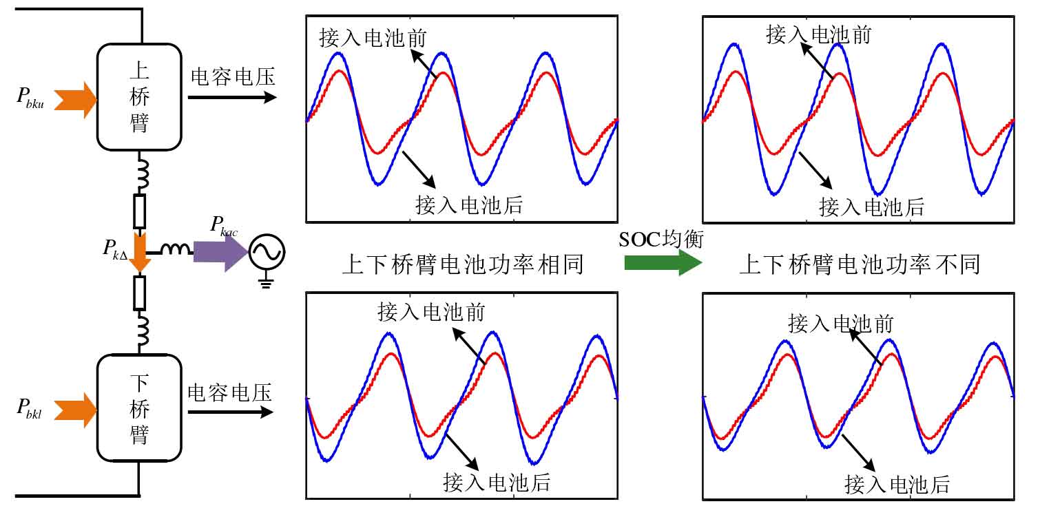
The introduction of battery energy storage systems has changed the power transmission mode in MMC, and capacitor voltage fluctuations will also exhibit different characteristics. According to simulation analysis, the capacitance voltage fluctuation amplitude of modular multilevel converter with battery energy storage system is greater than that of MMC with the same capacity. Taking a power transmission mode of modular multilevel converter with battery energy storage system as an example, as shown in Figure 13, the amplitude of capacitor voltage fluctuation significantly increases after the introduction of a battery energy storage system; When considering SOC equalization, the battery power injected into the upper and lower bridge arms is different, and the amplitude of capacitor voltage fluctuation in the upper and lower bridge arms is also different, with one bridge arm increasing and the other bridge arm decreasing. To limit the voltage fluctuation amplitude of the capacitor after introducing the battery energy storage system to a reasonable range, it is necessary to have larger submodule capacitors, which means larger volume and higher cost. Therefore, if the problem of increased capacitor voltage pulsation caused by the introduction of battery energy storage systems cannot be solved, the advantages of modular multilevel converter with battery energy storage system in practical engineering applications will be significantly reduced.
At present, there is no literature focusing on the suppression of capacitor voltage pulsation in modular multilevel converter with battery energy storage system. Relevant research is mainly focused on ordinary MMC, mainly divided into two categories: additional control schemes and improved topology method schemes. The additional control scheme does not change the topology structure, but improves the original control strategy to reduce the voltage ripple of the submodule capacitor. It mainly suppresses the voltage ripple of the capacitor by controlling the circulating current. Directly suppressing the second harmonic circulating current to zero can to some extent suppress capacitor voltage ripple. This method has a simple structure and is easy to implement in engineering, making it the most commonly used method for suppressing capacitor voltage ripple
Law. By optimizing the command of the second harmonic current, the suppression effect of capacitor voltage ripple can be further improved, but how to obtain the command value of the second harmonic current is a key issue. Injecting a third harmonic common mode voltage into the AC output voltage can improve the modulation ratio, and combining it with a second harmonic circulating current injection method can further improve the suppression effect of capacitor voltage pulsation. Additional control types require the use of circulating current control to suppress capacitor voltage fluctuations, which significantly increases the amplitude of bridge arm current, meaning larger capacity power devices and greater system losses.
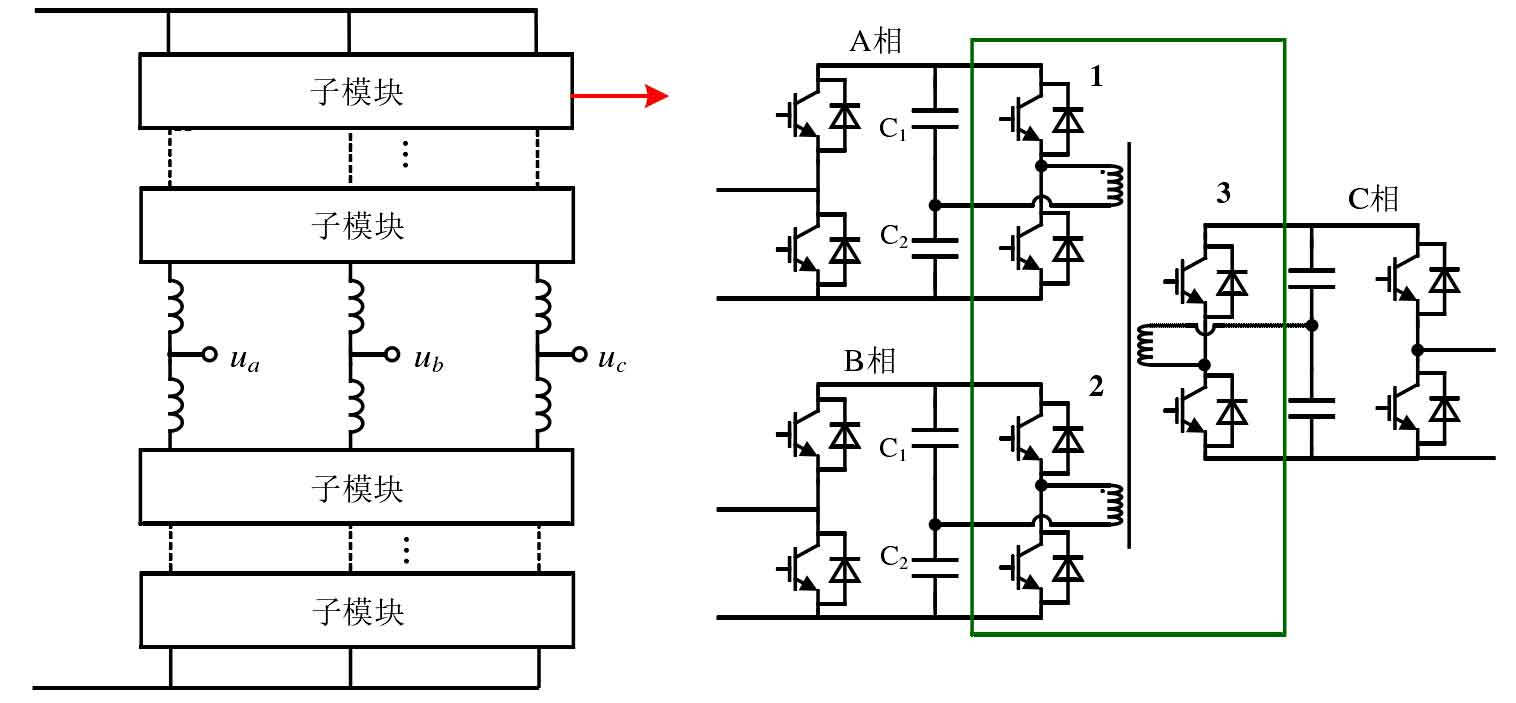
The improved topology scheme achieves capacitor voltage ripple suppression by appropriately improving the sub module structure or main circuit structure of MMC. By utilizing the negative level output capability of the full bridge submodule to improve the modulation ratio, and combining it with the method of secondary circulating current injection, the complete suppression of fundamental frequency and secondary pulsation was achieved. Finally, the capacitor voltage pulsation only contained the third component with smaller amplitude. Dynamically adjust the size of the corresponding bridge arm reactor to change the current distribution of the bridge arm, ultimately achieving a reduction in overall sub module capacitor voltage fluctuations. By establishing a power channel between the upper and lower bridge arms through an isolated DC/DC converter, the fundamental frequency component in capacitor voltage pulsation is eliminated. By establishing a power channel between three-phase submodules using an isolated three port DC/DC converter as shown in Figure 14, theoretically all capacitor voltage fluctuations can be eliminated. Compared to the additional control scheme, the suppression method based on power channel has the most ideal effect, but it requires the addition of additional power devices and high-frequency transformers, and the economy of the system needs to be evaluated.
In summary, the additional control scheme achieves the suppression of capacitor voltage pulsation through circulating current control, without the need for additional devices, and is currently the most commonly used method for suppressing capacitor voltage pulsation. However, modular multilevel converter with battery energy storage system is affected by multiple operating modes and SOC balance control, and the frequency components of its circulation, as well as the amplitude and phase of each frequency component, are significantly different from MMC. The above additional control schemes cannot achieve ideal capacitor voltage ripple suppression effect when directly applied to modular multilevel converter with battery energy storage system. The capacitor voltage ripple suppression effect of the improved topology scheme is significant, but its topology structure has undergone significant changes. When promoting its application to modular multilevel converter with battery energy storage system, it is also necessary to consider the issue of coordination with the battery energy storage system. Therefore, it is necessary to explore a capacitor voltage ripple suppression method suitable for modular multilevel converter with battery energy storage system based on existing research results.
3. Research content of this article
Modular multi-level converters can not only meet the requirements of renewable energy generation systems for medium to high voltage and high capacity power converters, but also provide interfaces for battery energy storage systems, forming a modular battery energy storage system. This structure is more conducive to system integration and coordinated control, facilitating the full utilization of battery energy storage systems, and is of great significance in solving problems such as renewable energy generation grid connection.
The main research content and ideas are shown in Figure 15. The first part focuses on the mathematical model and operational characteristics analysis of the MMC system, which is a fundamental problem of MMC and is also applicable to systems with integrated battery energy storage. Starting from the MMC AC port, the impact of internal coupling on the operating characteristics of the AC port is analyzed, and a more accurate equivalent circuit model is proposed. Based on the obtained model, the system control performance is improved. Then, starting from within the MMC system, an HSS model with internal multivariables and multiple control loops was established. Based on this model, the steady-state and dynamic characteristics of the system were analyzed, providing theoretical basis for the design of main circuit parameters, controller parameter tuning, stability analysis, and so on. The second part focuses on the new issues caused by the introduction of battery energy storage systems, including capacitor voltage balancing control and capacitor voltage pulsation suppression. A evaluation scheme for the balancing ability of submodules is proposed to address the issue of capacitor voltage balancing control. The balancing ability of submodules under different control strategies is analyzed, and an optimized control scheme to improve the balancing ability of submodules is studied. A battery connection MMC submodule structure based on an isolated three port DC/DC converter is proposed to address the issue of capacitor voltage ripple suppression, and a control strategy is designed that can simultaneously achieve battery power transmission and capacitor voltage ripple suppression. The specific research content is as follows:
(1) Analysis of MMC AC Port Operation Characteristics and Equivalent Circuit Model
Firstly, analyze the mechanism of internal coupling in MMC and reveal the specific coupling characteristics between circulating current, AC output current, and capacitor voltage. On this basis, the MMC AC port is equivalent to a two-level converter series equivalent impedance structure, and the harmonic linearization method is used to calculate the equivalent series impedance, thereby revealing the impact of internal coupling on the operating characteristics of the MMC AC port and obtaining an accurate AC port model. Then, further analyze the influence of factors such as loop control on the equivalent series impedance, and obtain its simplified analytical expression, making the AC port model more concise and intuitive, and convenient for practical application. Compare the steady-state and dynamic simulation results of the obtained AC port model with existing models to verify the accuracy of the model. Finally, based on the obtained equivalent circuit model, a high-performance power decoupling control strategy was designed, revealing the low-frequency oscillation mechanism of MMC when operating independently.
(2) Analysis of Internal Operating Characteristics of MMC Based on Harmonic State Space Theory
Firstly, a steady-state model of MMC based on HSS is established to obtain accurate steady-state solutions of internal electrical and control quantities under open-loop control and closed-loop control, providing a basis for the design of main circuit parameters and the evaluation of system economy and superiority; Further analyze the impact of secondary circulation control on steady-state performance indicators such as capacitor voltage ripple, bridge arm current peak, and bridge arm current effective value. Propose a comprehensive consideration of multiple performance indicators for secondary circulation optimization control, balancing various performance indicators to achieve overall system performance optimization. Then establish an HSS based MMC dynamic model, use eigenvalues to study the internal dynamic characteristics of the system, obtain stable boundaries for each controller parameter, and introduce participation factors to analyze the impact of AC loop control on internal control, as well as the mutual influence laws between internal control loops. Based on the precise analysis results of HSS theory, a simplified design method for controller parameters is proposed for practical engineering applications. Finally, the accuracy of the HSS model and analysis results in this paper was verified on simulation models and experimental platforms.
(3) Evaluation and Optimization of modular multilevel converter with battery energy storage system Neutron Module Equalization Capability
Firstly, the concept of sub module power imbalance is defined, and the balancing ability of the sub module is evaluated using the allowable range of imbalance in the system, which serves as the design basis for SOC balancing controller parameters. Then, evaluate the sub module balancing ability when using capacitor voltage closed-loop balancing control and capacitor voltage sorting balancing control, and analyze the impact of modulation ratio, battery power, and other factors on sub module balancing. On this basis, a capacitor voltage closed-loop equalization control sub module port voltage regulation scheme is proposed to solve the problem of low sub module equalization ability in high modulation ratio. Finally, an modular multilevel converter with battery energy storage system experimental platform and simulation model were built, and the simulation and experimental results verified the effectiveness of the proposed submodule balancing ability evaluation method and optimization control strategy.
(4) Battery Connection Method and Control Based on Isolated Three Port DC/DC Converter
Firstly, analyze the impact of battery power and its uneven distribution on capacitor voltage ripple. On this basis, a battery connection method based on an isolated three port DC/DC converter is proposed. The upper bridge arm submodule and the lower bridge arm submodule share a battery energy storage unit, and the three are connected through an isolated three-port DC/DC converter. Then, the working principle of the battery connection method was analyzed, as well as the power transmission method between the three ports when achieving battery power control and capacitor voltage ripple suppression. A mathematical model of an isolated three port DC/DC converter has been further established, and a control scheme that can simultaneously achieve battery power transmission and capacitor voltage ripple suppression has been proposed, and corresponding controller parameters have been designed. Finally, an modular multilevel converter with battery energy storage system experimental platform based on an isolated three port DC/DC converter was built to verify the effectiveness of the battery energy storage access method and control strategy proposed in this paper.