
In my analysis of advanced energy storage systems, I consistently return to one central material: lithium cobalt oxide, LiCoO2. Since its successful commercialization, LiCoO2 has remained a benchmark cathode for high-energy lithium-ion cells, especially in portable electronics, wearable devices, and emerging electric transportation platforms. The reason is straightforward: LiCoO2 combines a high operating voltage, a relatively flat discharge plateau, good electronic and ionic conductivity, and a mature and scalable synthesis route. Nevertheless, the same material also exposes the fundamental limits of layered oxide cathodes in lithium-ion cells. When the cutoff voltage is pushed beyond approximately 4.2 V, LiCoO2 suffers from structural degradation, interfacial side reactions, cobalt dissolution, oxygen release, and electrolyte decomposition. These coupled chemical and electrochemical failure modes reduce capacity retention, increase impedance, and compromise safety in lithium-ion cells.
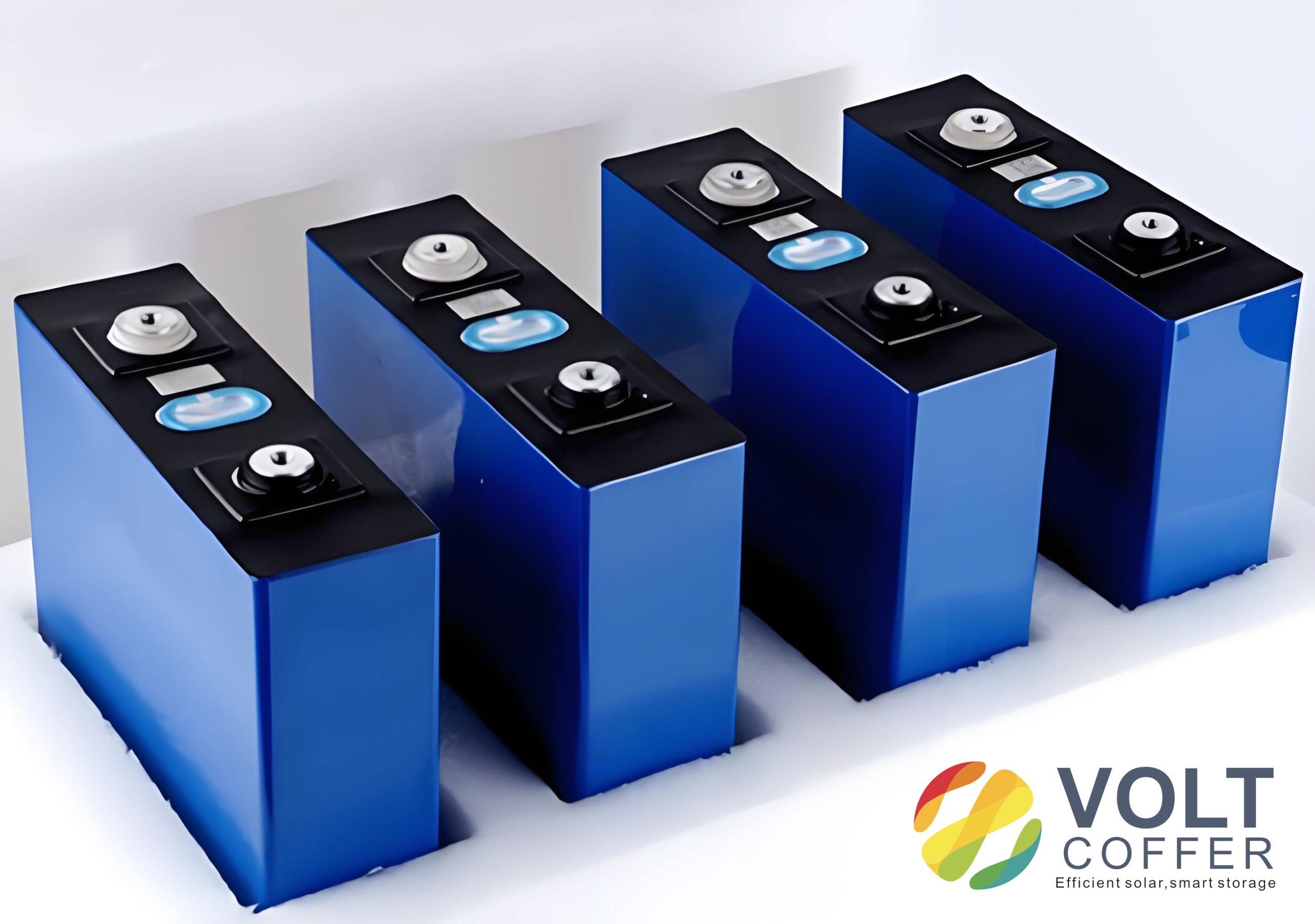
From my perspective, the modification of LiCoO2 is not a single problem but a hierarchy of problems spanning the atomic lattice, the particle surface, the electrode architecture, and the full lithium-ion cell. A useful modification strategy must therefore address more than one length scale. I organize the present discussion around nanonization, elemental doping, surface coating, and synergistic composite modification. I also use comparative tables and quantitative relations to clarify why certain strategies work, where they fail, and how they may be combined to extend the lifetime and energy density of lithium-ion cells.
Fundamental Properties of LiCoO2
LiCoO2 can exist in several structural forms, including a rock-salt phase, a spinel-like phase, and the layered phase. Among these, the layered α-NaFeO2-type structure with space group R-3m is the most electrochemically useful. In this structure, oxygen anions form a close-packed cubic framework. Cobalt cations occupy octahedral sites within CoO6 layers, while lithium cations occupy octahedral sites within LiO6 layers. The CoO6 octahedra share edges to form two-dimensional CoO2 slabs, and Li+ ions reside between these slabs. During charge and discharge in a lithium-ion cell, Li+ ions are extracted from and inserted into the interlayer galleries. Ideally, the CoO2 framework remains intact, allowing reversible lithium storage.
The theoretical specific capacity of LiCoO2 can be estimated from Faraday’s law:
$$ C_{th} = \frac{n F}{3.6 M_w} $$
Here, n is the number of electrons transferred per formula unit, F is the Faraday constant, and Mw is the molar mass. For LiCoO2, full extraction of one Li+ per formula unit corresponds to a very high theoretical capacity. In practice, only about half of the lithium can be reversibly removed in conventional lithium-ion cells without severe degradation. This practical limitation arises from the instability of the highly delithiated phase, anisotropic lattice changes, and parasitic reactions at the cathode-electrolyte interface.
The layered structure can be described by hexagonal lattice parameters a and c. The c/a ratio and the intensity ratio of certain X-ray diffraction peaks are often used as indicators of layered ordering. A higher degree of layered ordering generally correlates with better lithium transport and structural stability. The interlayer spacing along the c-axis influences the activation energy for Li+ migration:
$$ D_{Li^+} = D_0 \exp\left(-\frac{E_a}{k_B T}\right) $$
where DLi+ is the diffusion coefficient, D0 is the pre-exponential factor, Ea is the activation energy, kB is the Boltzmann constant, and T is temperature. Any modification that increases the interlayer spacing or reduces the migration barrier can improve rate capability in lithium-ion cells.
Table 1 summarizes the fundamental properties and limitations of LiCoO2 as a cathode in lithium-ion cells.
Table 1. Fundamental characteristics and limitations of layered LiCoO2 in lithium-ion cells.
| Property | Description | Consequence for lithium-ion cells |
|---|---|---|
| Crystal structure | Layered α-NaFeO2 type, space group R-3m | Provides two-dimensional Li+ diffusion pathways |
| Theoretical capacity | High, based on one-electron Co redox | Attractive for high-energy lithium-ion cells |
| Practical capacity | Limited by reversible Li extraction | Requires voltage optimization and stabilization |
| Operating voltage | Approximately 3.0–4.2 V vs. Li/Li+ | High energy density but limited by oxidative instability |
| Electronic conductivity | Moderate to good | Supports rate performance in lithium-ion cells |
| Ionic conductivity | Anisotropic, favored in the ab plane | Nanostructuring and doping can improve kinetics |
| Structural stability | Degrades above 4.2–4.3 V | Phase transitions, cracking, capacity fade |
| Interfacial stability | Reactive with organic electrolytes | Side reactions, gas evolution, Co dissolution |
| Cost and supply | Co is expensive and geographically constrained | Motivates doping, coating, and recycling |
Degradation Mechanisms in Lithium-Ion Cells
I find it essential to distinguish bulk degradation from interfacial degradation. Bulk degradation involves phase transformations, lattice strain, and oxygen loss, while interfacial degradation involves electrolyte oxidation, surface reconstruction, and transition-metal dissolution. In a lithium-ion cell, these processes are coupled. For example, oxygen release from the bulk can oxidize the electrolyte, and electrolyte decomposition can produce HF, which then attacks the cathode surface and dissolves cobalt.
One major failure mode is the phase transition from the layered R-3m phase to undesirable phases upon deep delithiation. This transition involves gliding of CoO2 slabs and changes in the stacking sequence. The associated volume change can be expressed as:
$$ \frac{\Delta V}{V_0} = \frac{V_{delithiated} – V_{lithiated}}{V_{lithiated}} \times 100\% $$
Large anisotropic volume changes generate microstrain, cracks, and particle fracture. Once cracks form, fresh surfaces are exposed to the electrolyte, accelerating side reactions. In addition, the highly oxidized Co4+ species formed during charging are strongly oxidizing and can catalyze electrolyte decomposition. This is particularly severe at high voltage in lithium-ion cells.
Oxygen release is another critical issue. The Co–O bonds become less stable when lithium is removed, and lattice oxygen can be oxidized to O2 or react with the electrolyte. The oxygen evolution reaction can be represented conceptually as:
$$ O^{2-}_{lattice} \rightarrow \frac{1}{2}O_2 + 2e^- $$
This process not only damages the lattice but also consumes charge that would otherwise be used for reversible lithium storage. The loss of lattice oxygen can also trigger surface reconstruction into a rock-salt-like or spinel-like layer, which has lower lithium conductivity.
Transition-metal dissolution is a further concern. In the presence of acidic species such as HF, cobalt ions can dissolve from the cathode and migrate to the anode, where they poison the solid-electrolyte interphase. The overall effect is increased cell impedance, reduced Coulombic efficiency, and accelerated capacity fade. The Coulombic efficiency of a lithium-ion cell can be written as:
$$ \eta_C = \frac{Q_{discharge}}{Q_{charge}} \times 100\% $$
When side reactions consume charge, ηC falls below unity. In modified LiCoO2 cathodes, improving ηC is often as important as improving absolute capacity.
Table 2 summarizes the main degradation mechanisms and their consequences.
Table 2. Degradation mechanisms of LiCoO2 in lithium-ion cells.
| Mechanism | Origin | Effect on lithium-ion cell | Mitigation strategy |
|---|---|---|---|
| Phase transition | Deep delithiation, slab gliding | Capacity fade, voltage decay | Doping, coating, nanosizing |
| Anisotropic volume change | Lattice expansion and contraction | Cracking, loss of contact | Porous architecture, single-crystal design |
| Oxygen release | Co–O bond instability | Electrolyte oxidation, thermal risk | Anion doping, surface coating |
| Electrolyte decomposition | High-voltage oxidation | Gas evolution, impedance rise | Protective coatings, electrolyte additives |
| Cobalt dissolution | HF attack, surface reconstruction | Anode poisoning, capacity loss | Surface coating, Al doping |
| Surface reconstruction | Oxygen loss, cation migration | Low ionic conductivity | Stable surface phases, gradient doping |
Nanonization of LiCoO2
Nanonization is one of the most intuitive ways to improve the rate performance of LiCoO2 in lithium-ion cells. By reducing particle size, I can shorten the solid-state diffusion path for Li+. The characteristic diffusion time is approximated by:
$$ t \approx \frac{L^2}{D_{Li^+}} $$
where L is the diffusion length. If L is reduced by a factor of ten, the diffusion time decreases by a factor of one hundred. This is why nanoscale LiCoO2 can deliver high capacity at high rates. However, nanonization is not a simple optimization. Excessive size reduction increases the specific surface area, which amplifies electrolyte decomposition, surface reconstruction, and irreversible lithium consumption. Therefore, I view nanonization as a double-edged strategy that must be coupled with surface stabilization.
Particle Size and Morphology Control
Research on particle size has shown that an optimal size window exists. If particles are too large, lithium diffusion limits rate performance. If particles are too small, interfacial side reactions dominate and cycling stability deteriorates. I can express the trade-off as a balance between diffusion improvement and surface reactivity:
$$ Performance = f\left(\frac{1}{L}, S_{surface}, Stability_{surface}\right) $$
In practice, this means that nanosized LiCoO2 must be engineered with controlled morphology. Plate-like or polygonal prismatic particles can expose favorable facets and reduce the fraction of high-energy surfaces. For example, flat polygonal prisms aligned along the c-axis have been reported to promote uniform lithium extraction and insertion. This uniformity reduces local stress and suppresses the formation of detrimental phases. In my assessment, morphology control is especially important for high-voltage lithium-ion cells because the surface reactivity increases sharply above 4.5 V.
Crystal Facet Engineering
Crystal facet engineering aims to expose surfaces that are both active for lithium transport and stable against electrolyte attack. The (001) facet is a basal plane of the layered structure. Although lithium diffusion is primarily two-dimensional within the ab plane, ultrathin single-crystal nanosheets with dominant (001) facets can still achieve high rate capability because the diffusion distance along the c-axis is very short. At the same time, a high fraction of (001) surfaces can reduce side reactions compared with edge surfaces. I summarize the facet effects in Table 3.
Table 3. Effects of morphology and facets on LiCoO2 performance in lithium-ion cells.
| Morphology or facet | Main advantage | Main limitation | Expected benefit in lithium-ion cell |
|---|---|---|---|
| Nanoparticles | Short Li+ diffusion path | High surface reactivity | Improved rate capability |
| Plate-like prisms | Uniform delithiation | Requires precise synthesis | Reduced strain and cracking |
| Ultrathin (001) nanosheets | Short c-axis path, stable basal surface | Low tap density | High-rate and stable cycling |
| Three-dimensional porous networks | Stress buffering, abundant active sites | Lower volumetric energy density | Long cycle life at moderate rate |
| Single-crystal particles | Fewer grain boundaries | Complex synthesis | Suppressed cracking |
Three-Dimensional Porous Architectures
Three-dimensional porous LiCoO2 can buffer volume changes and provide continuous lithium transport pathways. If I model the porosity as ε, the effective diffusion coefficient in the porous electrode can be approximated by:
$$ D_{eff} = D_{Li^+} \frac{\varepsilon}{\tau} $$
where τ is tortuosity. A well-designed porous network lowers tortuosity and increases electrolyte access, but excessive porosity reduces volumetric energy density. Therefore, the optimal architecture balances ionic transport against packing density. In lithium-ion cells intended for portable electronics, volumetric energy density is often critical, so porous LiCoO2 may be more suitable for high-power or fast-charging applications.
Elemental Doping of LiCoO2
Elemental doping is one of the most practical modification methods because it can be integrated into conventional solid-state synthesis. I can introduce metal or non-metal ions into the LiCoO2 lattice to stabilize the structure, suppress phase transitions, reduce lattice distortion, and improve lithium diffusion. The formation energy of a dopant can be written as:
$$ E_f = E_{tot}^{doped} – E_{tot}^{bulk} – \sum_i n_i \mu_i $$
Here, Etotdoped is the total energy of the doped system, Etotbulk is the total energy of the undoped system, ni is the number of exchanged atoms, and μi is the corresponding chemical potential. A lower formation energy generally indicates a more favorable dopant incorporation. However, thermodynamic favorability alone does not guarantee improved electrochemical performance; the dopant must also improve structural and interfacial stability in the lithium-ion cell environment.
Metal-Ion Doping
Metal-ion doping can be classified by valence and site preference. Low-valence dopants such as Mg2+ can occupy lithium sites and act as pillars that prevent layer sliding. High-valence dopants such as Ti4+, Zr4+, or Nb5+ can strengthen the Co–O framework and reduce oxygen loss. Al3+ is particularly attractive because Al–O bonds are strong and aluminum is inexpensive. When Al is introduced into LiCoO2, the Co–O framework becomes more resistant to oxygen release, and the material can tolerate higher cutoff voltages in lithium-ion cells.
Magnesium doping is also well known for stabilizing the layered structure. Mg2+ can occupy Li sites and suppress the phase transition that occurs during deep delithiation. Because Mg2+ is electrochemically inactive in the relevant voltage window, it does not contribute directly to capacity, but it acts as a structural support. I can describe the pillar effect as a reduction in the driving force for slab gliding:
$$ \Delta G_{glide} = \Delta G_{undoped} + n_{Mg} \Delta G_{pillar} $$
When ΔGpillar is positive, the energy barrier for gliding increases, and the layered structure becomes more stable. This is one reason why Mg doping improves cycling stability at high voltage.
Al doping has a different but complementary effect. Strong Al–O bonds increase the average metal–oxygen bond energy and suppress oxygen evolution. The bond energy effect can be expressed as:
$$ E_{M-O}^{avg} = \sum_i x_i E_{M_i-O} $$
where xi is the fraction of metal species. Increasing the fraction of Al–O bonds raises the average bond energy, making oxygen removal less favorable. In lithium-ion cells, this translates into improved high-voltage cycling and reduced gas generation.
Co-doping with multiple elements is often more effective than single doping. For example, Mg and Al can be combined to provide both pillar stabilization and bond strengthening. Ti and Mg can be combined to improve rate capability and structural stability. Table 4 summarizes common metal dopants and their effects.
Table 4. Metal dopants for LiCoO2 and their effects in lithium-ion cells.
| Dopant | Preferred site | Primary effect | Benefit for lithium-ion cell | Possible drawback |
|---|---|---|---|---|
| Mg2+ | Li site | Pillar effect, suppresses phase transition | Improved high-voltage cycling | Electrochemically inactive |
| Al3+ | Co site | Strong Al–O bonds | Suppressed oxygen release, lower cost | May reduce capacity if excessive |
| Ti4+ | Co site | Framework stabilization | Improved structural reversibility | Can reduce electronic conductivity |
| Zr4+ | Co site | Lattice stabilization | Better cycling at high voltage | Limited solubility |
| Nb5+ | Co site | Charge compensation, oxygen retention | Enhanced rate and stability | Complex synthesis control |
| Ni2+/3+ | Co site | Redox tuning | Higher capacity | Can accelerate phase transition |
| Mn4+ | Co site | Structural stabilization | Improved thermal stability | May lower operating voltage |
Non-Metal and Anion Doping
Non-metal doping usually involves substituting oxygen sites with F, Cl, Br, S, or P. Among these, fluorine is the most extensively studied. F doping forms strong Co–F bonds that anchor lattice oxygen and reduce irreversible oxygen release. The volume change during delithiation can be reduced. For example, a modified composition can show a maximum volume expansion of about 1.4%, compared with about 2.1% for undoped LiCoO2 under similar delithiation conditions. This reduction in volume change directly benefits the mechanical integrity of lithium-ion cells.
Chlorine doping introduces a larger anion radius and creates local geometric distortions. These distortions can increase the c-axis lattice parameter and lower the activation energy for Li+ migration. Reported activation energies for Cl-doped and Br-doped LiCoO2 can be as low as 0.12 eV and 0.09 eV, respectively, compared with much higher values for undoped or cation-doped materials. The relationship between activation energy and diffusivity is:
$$ \frac{D_{doped}}{D_{undoped}} = \exp\left(-\frac{E_{a,doped} – E_{a,undoped}}{k_B T}\right) $$
If the activation energy is reduced, the diffusion coefficient increases exponentially. This is a powerful argument for anion doping in fast-charging lithium-ion cells. However, large-radius anions can also cause excessive lattice distortion, which may lead to local stress concentration during long-term cycling.
Phosphorus doping often forms phosphate-like polyanions or occupies oxygen sites. The strong P–O bonds can pin the layered structure and suppress oxygen layer shear. This is analogous to inserting stoppers into a layered sliding system. The result is improved high-voltage stability, although electrochemically inert phases may slightly reduce reversible capacity. Sulfur doping can increase electronic conductivity and lithium diffusion because sulfur has a larger radius and different orbital energy than oxygen. The larger c-axis parameter lowers the migration barrier, but sulfur doping may also lower the lithium insertion potential. Table 5 summarizes anion doping effects.
Table 5. Non-metal and anion dopants for LiCoO2 in lithium-ion cells.
| Dopant | Substitution site | Key mechanism | Reported benefit | Potential risk |
|---|---|---|---|---|
| F | O site | Strong Co–F bonds, oxygen anchoring | Reduced oxygen release and volume change | Excess F may reduce capacity |
| Cl | O site | Larger anion radius, lattice expansion | Lower Li+ migration barrier | Lattice distortion |
| Br | O site | Maximum c-axis expansion | Very low activation energy | Long-term structural fatigue |
| P | O site or polyanion | Strong P–O bonds, structural pinning | High-voltage stability | Inactive phase formation |
| S | O site | Increased electronic conductivity | Improved charge transfer | Lower insertion potential |
Surface Coating of LiCoO2
Surface coating is a direct way to protect LiCoO2 from the electrolyte in lithium-ion cells. Even if the bulk structure is stabilized by doping, the surface remains vulnerable to electrolyte oxidation, HF attack, and oxygen loss. A coating can physically separate the cathode from the electrolyte, reduce the contact area for side reactions, and provide a stable interface for lithium transport. The ideal coating should have the following properties: high chemical stability, high ionic conductivity, moderate electronic conductivity, good adhesion, and compatibility with the cathode and electrolyte.
The effect of a coating on interfacial resistance can be described by:
$$ R_{total} = R_{bulk} + R_{coating} + R_{ct} $$
where Rbulk is the bulk resistance, Rcoating is the coating resistance, and Rct is the charge-transfer resistance. A good coating should increase Rcoating only slightly while significantly reducing Rct by suppressing interfacial degradation. If the coating is too thick or insulating, it blocks lithium transport and hurts rate performance.
Inorganic Non-Metal Coatings
Inorganic non-metal coatings include oxides, phosphates, fluorides, and carbon-based materials. These coatings often have good chemical and thermal stability. For example, an epitaxial α-LiAlO2 coating can protect LiCoO2 from electrolyte corrosion and suppress structural degradation at high voltage. The lattice-matched interface can also provide continuous lithium diffusion pathways. Phosphate-based coatings such as LiMgxNi1−xPO4 can stabilize the cathode-electrolyte interface and reduce cobalt dissolution. Carbon nanotube coatings can improve electronic contact and distribute mechanical stress. In one approach, a dense carbon nanotube cocoon around LiCoO2 particles expanded the effective electrical contact area and maintained about 94% capacity after 400 cycles at 4.55 V. This illustrates how coating architecture can influence both mechanics and electrochemistry in lithium-ion cells.
However, inorganic coatings are sometimes incomplete or point-like. They may not fully cover the surface, leaving regions exposed to the electrolyte. Therefore, coating uniformity and thickness control are critical. The coating thickness h affects both protection and impedance:
$$ R_{coating} = \frac{h}{\sigma_{coating} A} $$
where σcoating is the coating conductivity and A is the area. As h increases, protection improves but resistance increases. There is an optimal thickness that maximizes performance.
Polymer Coatings
Polymer coatings offer flexibility, elasticity, and the ability to accommodate volume changes. They can also improve interfacial contact and suppress electrolyte decomposition. Examples include sulfone-based polymers, cross-linked polyacrylonitrile, and gel polymer electrolytes such as P(VDF-HFP)/LiTFSI. A polymer coating can act as a physical barrier and an ionic conductor. Because polymers are flexible, they can maintain coverage even when the LiCoO2 particles expand and contract during cycling. This is especially valuable in lithium-ion cells that operate at high voltage or elevated temperature.
For a polymer coating, the ionic conductivity can be expressed as:
$$ \sigma_{ion} = \sum_i n_i q_i \mu_i $$
where ni is the carrier concentration, qi is the charge, and μi is the mobility. Polymer coatings with high lithium salt content and low crystallinity tend to have higher ionic conductivity. Cross-linking can improve mechanical strength but may reduce chain mobility and ionic conductivity. Therefore, the design of polymer coatings requires a balance between mechanical robustness and ionic transport.
Table 6 compares common coating materials and their functions.
Table 6. Surface coating materials for LiCoO2 in lithium-ion cells.
| Coating type | Examples | Main function | Advantage | Limitation |
|---|---|---|---|---|
| Oxide | Al2O3, LiAlO2, ZrO2 | Physical barrier, HF scavenging | Chemically stable | May be insulating |
| Phosphate | LiMgPO4, Li3PO4 | Interface stabilization | Good ionic conduction | Processing complexity |
| Carbon | Carbon nanotubes, graphene | Electronic conduction, stress buffering | High conductivity | May catalyze side reactions |
| Polymer | Sulfone polymers, PAN, gel electrolytes | Flexible barrier, ionic transport | Accommodates volume change | Swelling and stability issues |
| Composite | Oxide–polymer, phosphate–carbon | Multifunctional protection | Synergistic effects | Optimization is complex |
Synergistic Doping and Coating
In my view, the most promising route for LiCoO2 in high-energy lithium-ion cells is the combination of doping and coating. Doping stabilizes the bulk lattice, while coating stabilizes the surface. Together, they address both bulk and interfacial degradation. For example, Al doping combined with Al2O3 coating can improve overcharge safety. The Al doping increases structural stability, and the Al2O3 coating suppresses electrolyte decomposition at the surface.
Another effective combination is Mg doping with a LiMgPO4/Li3PO4 coating. The bulk Mg doping modifies the Co 3d and O 2p band centers, increasing the band gap and enhancing Co–O ionicity. This suppresses oxygen redox and oxygen release. The surface phosphate coating inhibits side reactions and facilitates lithium diffusion. A lithium-ion cell using such a modified cathode can deliver about 149.8 mAh g−1 after 200 cycles at 4.60 V, about 146.1 mAh g−1 at 4.65 V, and about 144.9 mAh g−1 after 150 cycles at 4.7 V. Even at 4.8 V, about 136.8 mAh g−1 can be retained after 100 cycles. These values demonstrate the power of synergistic modification.
The electronic structure effect of doping can be represented by the band gap:
$$ E_g = E_c – E_v $$
If doping increases Eg and shifts the O 2p band to lower energy relative to the Fermi level, oxygen redox becomes less favorable, and the lattice oxygen is better retained. This is one reason why Mg doping improves high-voltage stability.
Table 7 summarizes representative synergistic modification systems and their reported benefits.
Table 7. Synergistic doping–coating strategies for LiCoO2 in lithium-ion cells.
| Bulk modification | Surface modification | Key synergy | Reported performance |
|---|---|---|---|
| Al doping | Al2O3 coating | Structural stability plus surface passivation | Improved overcharge safety |
| Mg doping | LiMgPO4/Li3PO4 coating | Band structure tuning plus interface protection | Stable cycling up to 4.8 V |
| Trace S doping | Li2SO4 coating | Anion doping plus protective sulfate layer | High capacity retention at 4.5 V |
| Ni and Mg co-doping | LiMgxNi1−xPO4 coating | Phase suppression plus interface stabilization | Enhanced 4.7 V cycling |
| Ti and Mg co-doping | Oxide coating | Framework stabilization plus HF resistance | Improved rate and cycle life |
Performance Metrics and Comparative Analysis
To compare modification strategies, I use several metrics: initial Coulombic efficiency, discharge capacity, capacity retention, rate capability, voltage decay, impedance growth, and thermal stability. The capacity retention can be calculated as:
$$ R = \frac{Q_{after}}{Q_{initial}} \times 100\% $$
Energy density is the product of average voltage and capacity:
$$ E = V_{avg} \times Q $$
For lithium-ion cells, increasing Vavg is attractive because energy density increases linearly. However, high voltage also accelerates degradation. Therefore, the goal of modification is to raise the usable voltage without sacrificing cycle life. Table 8 compares the main modification strategies.
Table 8. Comparison of LiCoO2 modification strategies for lithium-ion cells.
| Strategy | Primary target | Advantages | Disadvantages | Best use case |
|---|---|---|---|---|
| Nanonization | Kinetics | Short diffusion path, high rate | High surface reactivity, low packing density | Fast-charging lithium-ion cells |
| Metal doping | Bulk structure | Suppresses phase transition, stabilizes lattice | Can reduce capacity | High-voltage lithium-ion cells |
| Anion doping | Lattice oxygen and diffusion | Reduces oxygen release, lowers migration barrier | Lattice distortion risk | High-voltage and fast-charging cells |
| Inorganic coating | Interface | Physical barrier, HF resistance | May be insulating or incomplete | High-temperature lithium-ion cells |
| Polymer coating | Interface and mechanics | Flexible, accommodates volume change | Swelling, limited stability | Flexible or high-voltage cells |
| Synergistic doping–coating | Bulk and interface | Multifunctional, best overall stability | Complex optimization | Next-generation high-energy cells |
I also note that the performance of modified LiCoO2 depends strongly on the electrolyte, binder, conductive additive, and electrode architecture. A coating that works well in one electrolyte may fail in another. Therefore, I recommend that modification studies report full lithium-ion cell data whenever possible, including areal capacity, electrolyte composition, cutoff voltage, and temperature. Without such standardization, cross-study comparison is difficult.
Future Directions
From my perspective, future work on LiCoO2 should proceed along five interconnected directions.
First, nanonization should become more precise and scalable. Simple size reduction is insufficient. I need synthesis routes that control particle size, shape, facet exposure, and porosity simultaneously. The optimal morphology for a given lithium-ion cell chemistry may differ for high-power, high-energy, or extreme-temperature applications. I also need to understand how nanoscale surfaces reconstruct under realistic cycling conditions.
Second, doping should move toward multi-element and high-entropy designs. Single-element doping often improves one property at the expense of another. Multi-element doping can provide complementary effects, such as Mg for pillar stabilization, Al for bond strengthening, Ti for framework stabilization, and F for oxygen anchoring. High-entropy doping may create local lattice distortions that improve ionic transport while suppressing phase transitions. However, the interactions among multiple dopants are complex. I believe that density functional theory, molecular dynamics, and machine learning will be essential to predict stable dopant combinations and understand synergistic mechanisms.
Third, coating science needs a deeper mechanistic foundation. I still lack a complete picture of how lithium ions move through different coating materials and how the coating–cathode interface evolves during cycling. Advanced characterization techniques and multiscale modeling can reveal ion transport pathways, defect formation, and mechanical failure at the interface. Multi-layer coatings and gradient coatings are promising, but they must be designed with clear transport and protection functions.
Fourth, synergistic modification should be guided by computation and data. The combination of nanonization, doping, and coating can exceed the performance of any single strategy, but the design space is enormous. Computational screening can identify promising combinations before extensive experimental work. Machine learning can extract patterns from existing datasets and suggest new compositions or architectures. In my view, this integrated approach will accelerate the development of LiCoO2 cathodes that simultaneously achieve high voltage, fast charging, long cycle life, and improved safety in lithium-ion cells.
Fifth, LiCoO2 should be adapted for solid-state lithium-ion cells. Solid electrolytes can potentially eliminate flammable liquid electrolytes and enable lithium metal anodes, but they also introduce new interfacial challenges. The interface between LiCoO2 and a solid electrolyte can suffer from chemical reactions, space-charge layers, and mechanical contact loss. Future work must develop high-voltage-compatible solid electrolytes and stable cathode coatings that maintain ionic contact during cycling. If successful, solid-state lithium-ion cells with modified LiCoO2 could achieve both high energy density and high safety.
Conclusion
I have examined the fundamental properties, degradation mechanisms, and modification strategies of LiCoO2 cathodes for lithium-ion cells. LiCoO2 remains attractive because of its high operating voltage, good rate capability, and mature manufacturing base. However, its practical capacity and high-voltage stability are limited by phase transitions, oxygen release, electrolyte oxidation, cobalt dissolution, and interfacial reconstruction. Nanonization improves kinetics but increases surface reactivity. Elemental doping stabilizes the bulk lattice and can suppress oxygen loss. Surface coating protects the interface and reduces side reactions. Synergistic doping–coating strategies offer the most balanced improvement and have already demonstrated stable cycling at voltages as high as 4.7–4.8 V in lithium-ion cells.
In my assessment, the next generation of LiCoO2 cathodes will not rely on a single modification method. Instead, they will integrate controlled nanostructure, multi-element doping, engineered coating layers, and optimized electrolyte interfaces. Computational design, advanced characterization, and standardized testing will be critical. By combining these approaches, I believe it is possible to extend the usable voltage, capacity, and lifetime of LiCoO2 in lithium-ion cells while maintaining safety and economic viability. The resulting materials will support high-performance portable electronics, electric vehicles, and solid-state energy storage systems, and they will also provide valuable lessons for the broader family of layered oxide cathodes.