
In my research, I focus on the design and validation of a data acquisition system for a solar inverter based on the MODBUS-RTU protocol. The motivation for this work comes from the rapid expansion of photovoltaic generation and the increasing need to monitor, manage, and optimize solar inverter operation in distributed and remote photovoltaic plants. A solar inverter is not merely a power conversion device; it is the central interface between photovoltaic modules and the electrical grid. Therefore, the data acquired from a solar inverter determines how effectively operators can understand energy yield, detect faults, evaluate efficiency, and schedule maintenance. In my design, I treat the solar inverter as the primary data source, the MODBUS-RTU protocol as the communication foundation, RS485 as the physical serial bus, and a 4G wireless link as the remote transmission path. This combination allows a solar inverter data acquisition system to perform real-time measurement, standardized communication, and remote supervision.
The traditional data acquisition approach for a solar inverter often relies on local displays, custom serial protocols, and on-site inspection. Such an approach creates several limitations. First, communication protocols may differ between manufacturers, which makes integration difficult. Second, local-only monitoring prevents timely remote management. Third, large physical size and high power consumption restrict deployment in compact outdoor environments. Fourth, maintenance is expensive when a solar inverter must be visited physically for configuration or troubleshooting. My work addresses these limitations by introducing a compact, standardized, and network-enabled data acquisition system that communicates with a solar inverter through MODBUS-RTU over RS485 and uploads data through TCP/IP over a 4G module. The system is intended to acquire voltage, current, power, energy, frequency, temperature, and status data from a solar inverter and present the results on a distributed photovoltaic operation platform.
Research Background and Motivation
Energy transformation is one of the defining technical and social challenges of the present century. Conventional energy sources have driven industrial development, but they also create environmental pressure, resource depletion, and long-term supply uncertainty. Renewable energy offers a different path because it is cleaner, more sustainable, and more widely available. Among renewable resources, solar energy is especially attractive because it is abundant, geographically distributed, and directly convertible into electricity. Photovoltaic generation uses the photovoltaic effect to convert solar irradiance into direct current, and a solar inverter converts that direct current into alternating current suitable for local loads or grid connection.
Because a solar inverter is the key power electronic interface in a photovoltaic system, its operating data are highly valuable. The output voltage of a solar inverter, output current, active power, reactive power, grid frequency, daily energy, cumulative energy, direct-current voltage, direct-current current, module temperature, and fault status all provide information about system health. If these values are collected continuously, they can support performance analysis, fault diagnosis, remote control, and predictive maintenance. My research is therefore motivated by a practical requirement: I need a data acquisition system that can read the internal registers of a solar inverter in a standardized way, store and convert the readings, and transmit them to a remote platform.
In my view, the value of a solar inverter data acquisition system can be summarized by several objectives:
| Objective | Explanation | Importance for Solar Inverter Monitoring |
|---|---|---|
| Real-time acquisition | Read electrical and status parameters at fixed intervals | Allows immediate visibility of solar inverter behavior |
| Standard communication | Use MODBUS-RTU as a common protocol | Reduces integration effort across different solar inverter models |
| Remote transmission | Upload data through TCP/IP and 4G | Supports management of distributed solar inverter sites |
| Data integrity | Use CRC and frame validation | Protects solar inverter measurements from corruption |
| Compact hardware | Use a small embedded controller and modular circuits | Makes the system suitable for outdoor cabinets |
| Maintainability | Support remote upgrade and parameter configuration | Reduces travel and labor cost for solar inverter maintenance |
The growth of photovoltaic capacity has made the monitoring problem more urgent. When many solar inverter units are installed across a wide area, manual inspection cannot provide sufficient temporal or spatial coverage. A data acquisition system must therefore collect data automatically and send it to a central platform. My design follows this principle: the solar inverter is connected locally to an embedded acquisition terminal, and the terminal communicates with a remote operation platform. This architecture transforms a solar inverter from an isolated power device into a networked and observable asset.
Review of Related Development
International research into photovoltaic monitoring began earlier than many domestic efforts and has produced mature data acquisition architectures. Early systems concentrated on basic measurement, data logging, and local control. Over time, researchers added grid interaction, power quality analysis, and remote communication. International projects have often emphasized database construction, long-term performance evaluation, and standardized data collection from multiple photovoltaic plants. These efforts demonstrate that a solar inverter data acquisition system must not only read values but also preserve data quality, time consistency, and system interoperability.
Domestic research and industrial development have expanded rapidly along with photovoltaic installation capacity. Many early systems were developed for specific solar inverter brands or specific plants. This led to a common problem: a data acquisition device might work well with one solar inverter model but fail with another because the communication protocol, register map, or data format differs. In addition, some systems lacked networking capability and depended on local serial communication. This reduced their usefulness for remote operation. My design responds to these issues by adopting MODBUS-RTU, a widely accepted industrial protocol, and by adding a 4G wireless module for remote connectivity. In this way, I aim to improve adaptability, reduce maintenance difficulty, and increase the intelligence of solar inverter monitoring.
Three technical gaps are especially important in my analysis:
| Gap | Traditional Limitation | My Design Response |
|---|---|---|
| Protocol inconsistency | Custom frames and vendor-specific commands | MODBUS-RTU with standard function codes and CRC |
| Limited networking | Local display or isolated serial link | 4G module with TCP/IP communication |
| Large and inflexible hardware | Bulky acquisition cabinets and fixed wiring | Compact embedded controller and modular interfaces |
| Weak remote maintenance | On-site configuration and manual upgrade | Remote parameter configuration and firmware upgrade support |
| Poor scalability | One device often supports only one solar inverter | RS485 multidrop bus for multiple solar inverter units |
Overall System Architecture
In my design, the overall system consists of two major parts: a local acquisition terminal and a remote operation platform. The local acquisition terminal is built around an embedded microcontroller. It connects to a solar inverter through an RS485 interface and communicates using MODBUS-RTU. The remote operation platform receives data through a 4G wireless module and TCP/IP. The local terminal performs register polling, frame parsing, CRC verification, data conversion, temporary storage, and network transmission. The remote platform performs visualization, storage, alarm display, and remote configuration.
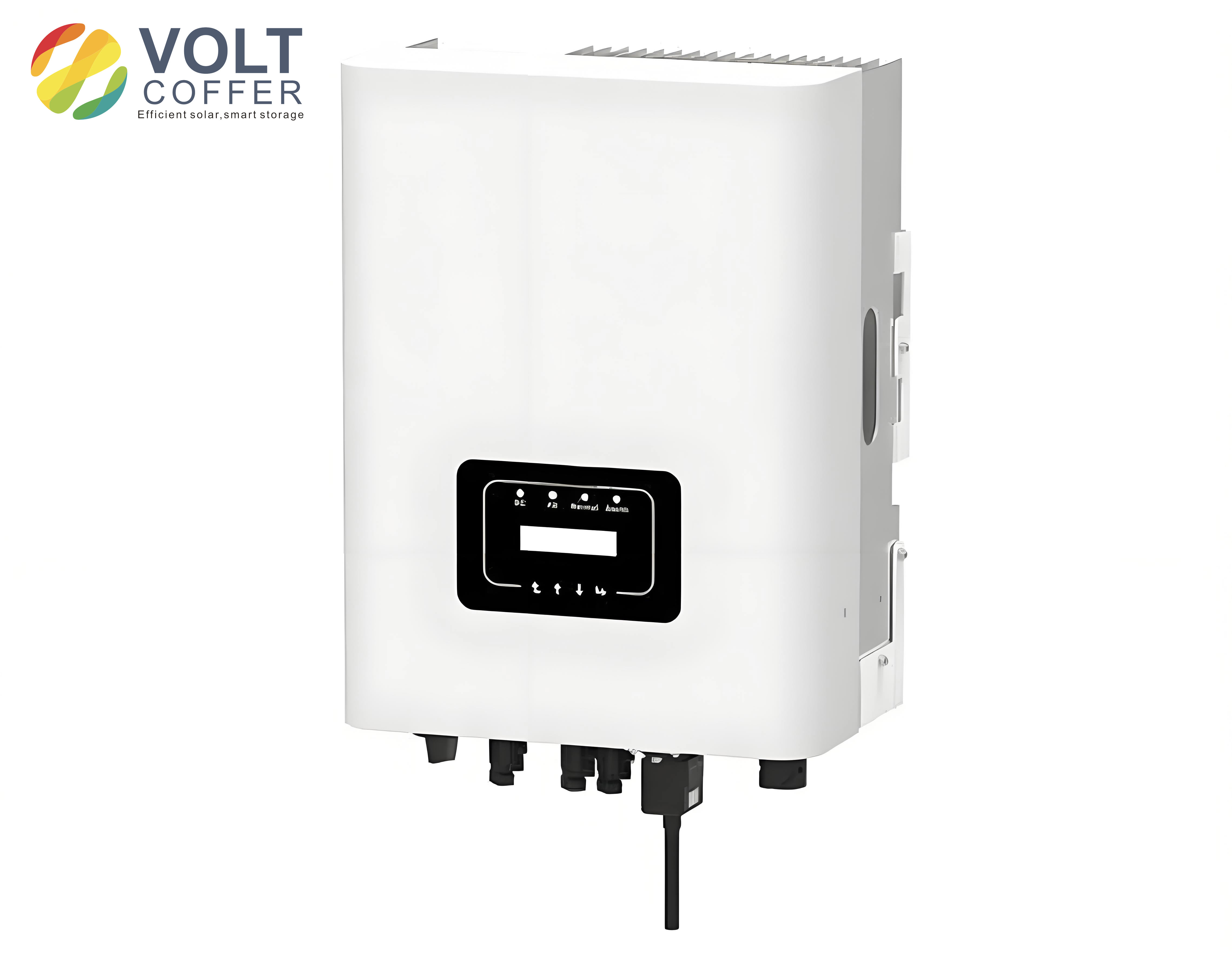
The data flow can be expressed as a sequence of transformations. Let \(D_{SI}\) represent the raw register data inside a solar inverter. Let \(F_{RTU}\) represent the MODBUS-RTU frame transmitted over RS485. Let \(D_{proc}\) represent the processed measurement after scaling and type conversion. Let \(P_{remote}\) represent the data displayed on the remote platform. The relationship is:
$$D_{SI} \rightarrow F_{RTU} \rightarrow D_{proc} \rightarrow P_{remote}$$
Each arrow implies validation, conversion, or transmission. The first arrow is performed by the solar inverter communication interface. The second arrow is performed by my embedded acquisition terminal. The third arrow is performed by the 4G module and the remote server. The reliability of the complete chain depends on the weakest stage, so I designed the system to validate frames, check CRC, manage timeouts, and retry failed requests.
| Layer | Function | Implementation in My System |
|---|---|---|
| Physical layer | Electrical signaling and wiring | RS485 differential bus between acquisition terminal and solar inverter |
| Data link layer | Frame delimiting and error detection | MODBUS-RTU timing and CRC16 |
| Application layer | Register read and write commands | Function codes such as 0x03 and 0x04 |
| Processing layer | Scaling, type conversion, storage | Embedded firmware on the microcontroller |
| Network layer | Remote transport | TCP/IP over 4G |
| Presentation layer | Visualization and alarm | Distributed photovoltaic operation platform |
MODBUS-RTU Protocol Foundation
MODBUS is a master-slave protocol. In my system, the embedded acquisition terminal acts as the master, and the solar inverter acts as the slave. Only the master initiates communication. The slave responds when it receives a valid request addressed to its unique slave address. This model is suitable for a solar inverter data acquisition system because one acquisition terminal can poll multiple solar inverter units on the same RS485 bus by using different slave addresses. A solar inverter that is not addressed ignores the frame, while the addressed solar inverter returns a response.
The MODBUS application data unit contains a protocol data unit and additional fields. In MODBUS-RTU, the frame is binary and is delimited by silent intervals. A typical request contains the slave address, function code, starting register address, register quantity, and CRC. A typical response contains the slave address, function code, byte count, data bytes, and CRC.
| Field | Request Size | Response Size | Purpose |
|---|---|---|---|
| Slave address | 1 byte | 1 byte | Identifies the target solar inverter |
| Function code | 1 byte | 1 byte | Defines read or write operation |
| Register address | 2 bytes | Not always present | Starting address in the solar inverter map |
| Register quantity | 2 bytes | Not always present | Number of registers to access |
| Byte count | Not always present | 1 byte | Number of data bytes returned |
| Data | Variable | Variable | Register values from the solar inverter |
| CRC | 2 bytes | 2 bytes | Error detection |
The MODBUS-RTU timing rule is critical. A frame must be preceded and followed by a silent interval of at least 3.5 character times. If the interval between two characters is greater than 1.5 character times, the receiver may treat the frame as incomplete or corrupted. The character time depends on the serial format and baud rate. For a frame with one start bit, eight data bits, no parity, and one stop bit, the number of bits per character is 10. Therefore, the character time is:
$$T_{char} = \frac{10}{B}$$
where \(B\) is the baud rate in bits per second. The silent interval is:
$$T_{3.5} = 3.5 T_{char} = \frac{35}{B}$$
For example, at \(B = 9600\) bps, \(T_{char} \approx 1.0417\) ms and \(T_{3.5} \approx 3.6458\) ms. These values guide the timer configuration in my firmware. If the silence threshold is too short, a single frame may be split into multiple fragments. If it is too long, response latency increases. I therefore configure the timer according to the selected baud rate and the actual frame format of the solar inverter.
| Baud Rate | 10-bit Character Time | 3.5-character Silence | Typical Use |
|---|---|---|---|
| 4800 bps | 2.0833 ms | 7.2917 ms | Long cable, low-speed solar inverter |
| 9600 bps | 1.0417 ms | 3.6458 ms | Common solar inverter polling |
| 19200 bps | 0.5208 ms | 1.8229 ms | Medium-speed acquisition |
| 38400 bps | 0.2604 ms | 0.9115 ms | Higher-speed local bus |
| 57600 bps | 0.1736 ms | 0.6076 ms | Short-distance high-speed link |
| 115200 bps | 0.0868 ms | 0.3038 ms | Fast local communication |
MODBUS-RTU and MODBUS-ASCII differ in encoding, check method, and frame boundary. In my design, I choose MODBUS-RTU because it is more efficient for binary register data and is widely supported by solar inverter manufacturers. The following table summarizes the comparison.
| Feature | MODBUS-RTU | MODBUS-ASCII |
|---|---|---|
| Encoding | Binary | ASCII hexadecimal |
| Frame boundary | Time-based silence | Start and end characters |
| Check method | CRC16 | LRC |
| Data density | Higher | Lower |
| Efficiency | Better for dense register data | Easier for manual reading |
| Use in my solar inverter system | Selected | Not selected |
The CRC polynomial used by MODBUS is:
$$G(x) = x^{16} + x^{15} + x^2 + 1$$
The seed value is 0xFFFF. The CRC is calculated over all bytes except the CRC field itself. In my firmware, I implement a table-free or table-based CRC16 routine and compare the calculated value with the received value. If the values do not match, the frame is discarded, and the acquisition terminal waits for the next response or retries the request. This process is essential because a solar inverter may be installed in an electrically noisy environment, and an unchecked error could corrupt a voltage, current, or energy value.
Function codes define the operation. For a solar inverter, read operations are the most common because the acquisition terminal mainly reads measurements and status registers. The following function codes are relevant to my design.
| Function Code | Name | Typical Use in Solar Inverter Monitoring |
|---|---|---|
| 0x03 | Read Holding Registers | Read configuration and measurement registers |
| 0x04 | Read Input Registers | Read real-time solar inverter measurements |
| 0x06 | Write Single Register | Set a parameter in the solar inverter |
| 0x10 | Write Multiple Registers | Configure a group of solar inverter parameters |
A request example for reading input registers from a solar inverter can be written as:
$$[A][04][Addr_H][Addr_L][Num_H][Num_L][CRC_H][CRC_L]$$
A normal response is:
$$[A][04][ByteCount][Data_0][Data_1]\cdots[Data_{n-1}][CRC_H][CRC_L]$$
An exception response uses the original function code with the highest bit set, followed by an exception code. For example, if the requested register address is invalid, the solar inverter may return an exception frame. My firmware checks for exception responses and records them as communication faults.
| Exception Code | Meaning | Handling in My Design |
|---|---|---|
| 0x01 | Illegal function | Log unsupported command for solar inverter |
| 0x02 | Illegal data address | Check solar inverter register map |
| 0x03 | Illegal data value | Validate scaling and parameter range |
| 0x04 | Slave device failure | Retry and report solar inverter fault |
| 0x05 | Acknowledge | Wait for completion |
| 0x06 | Slave device busy | Delay and retry |
RS485 Serial Communication Design
I selected RS485 as the physical layer for the solar inverter communication link. RS485 uses differential signaling, which improves immunity to common-mode noise. This is important because a solar inverter can generate strong electromagnetic interference due to high-frequency switching. RS485 also supports multidrop connection, allowing one acquisition terminal to communicate with multiple solar inverter units on the same bus. The differential voltage is:
$$V_{AB} = V_A – V_B$$
In a typical RS485 transceiver, a positive differential voltage above a certain threshold represents one logic state, and a negative differential voltage below the opposite threshold represents the other logic state. The exact thresholds depend on the transceiver, but the differential nature provides better noise margin than a single-ended interface.
I compared RS232 and RS485 before making the design choice. The comparison is shown below.
| Feature | RS232 | RS485 |
|---|---|---|
| Signal mode | Single-ended | Differential |
| Duplex | Full duplex | Half duplex in my design |
| Typical distance | Short | Up to about 1000 m at low speed |
| Multidrop support | Limited | Good |
| Noise immunity | Moderate | High |
| Suitability for solar inverter | Local only | Selected for field bus |
In my circuit, an RS485 transceiver connects the microcontroller UART to the A and B differential lines. The transceiver has a receiver output, a driver input, and enable pins. The receiver enable and driver enable are controlled so that the device is in receive mode by default and switches to transmit mode only when sending a request to the solar inverter. A common failure mode in half-duplex RS485 is bus contention, which occurs if two devices drive the bus at the same time. My firmware avoids this by using a strict master-slave schedule and by releasing the driver after each request frame.
| Transceiver Pin | Function | Connection in My Design |
|---|---|---|
| RO | Receiver output | Connected to MCU RX |
| DI | Driver input | Connected to MCU TX |
| RE | Receiver enable, active low | Tied with DE for direction control |
| DE | Driver enable, active high | Controlled by MCU GPIO |
| A | Non-inverting differential line | Connected to bus A with protection |
| B | Inverting differential line | Connected to bus B with protection |
| VCC | Power supply | 3.3 V or 5 V depending on transceiver |
| GND | Ground reference | Common ground with the acquisition board |
The maximum practical cable length depends on baud rate and cable capacitance. A useful engineering approximation is that the product of bit rate and cable length should remain within a bounded region. For a given cable capacitance per unit length \(C’\), the RC time constant of the bus is:
$$\tau = R_{term} C’ L$$
where \(L\) is cable length and \(R_{term}\) is the termination resistance. To keep signal integrity acceptable, the bit period should be much larger than \(\tau\). In my system, I use a moderate baud rate for the solar inverter bus and keep the cable as short as practical. I also add transient protection devices to protect the RS485 transceiver from surges that may couple into long outdoor cables.
Hardware Design
For the hardware, I chose an ARM Cortex-M3 based microcontroller as the main controller. The selected device provides sufficient processing capability, multiple UART interfaces, an analog-to-digital converter, DMA support, timers, and low power consumption. The microcontroller acts as the central unit of the solar inverter data acquisition system. It executes the MODBUS-RTU master logic, controls the RS485 direction pin, manages the 4G module through AT commands, and performs data conversion and storage.
| Requirement | Design Consideration | Selected Feature |
|---|---|---|
| Processing | MODBUS parsing and data conversion | 32-bit ARM Cortex-M3 core |
| Serial communication | RS485 to solar inverter and 4G module | Multiple UART interfaces |
| Analog acquisition | Local voltage signal measurement | ADC with DMA |
| Timing | RTU frame separation and timeout | Hardware timers |
| Power | Low consumption for outdoor use | Low-power modes and wide supply range |
| Debug | Online programming and debugging | SWD interface |
The minimum system consists of the microcontroller, clock circuit, reset circuit, power supply, and download/debug interface. The clock circuit uses a high-frequency crystal for precise timing and a low-frequency crystal for timekeeping. The reset circuit ensures that the microcontroller starts only after the supply voltage is stable. The power circuit converts the input supply to the required 3.3 V rail. The debug interface allows firmware download and online debugging.
| Circuit Block | Purpose | Key Parameters |
|---|---|---|
| Main controller | Execute firmware and control peripherals | 32-bit core, multiple UARTs, ADC, DMA |
| High-speed clock | Provide system clock | 8 MHz crystal with PLL |
| Low-speed clock | Provide real-time timing | 32.768 kHz crystal |
| Reset | Ensure reliable startup | RC or supervisor reset |
| Power | Provide stable 3.3 V | 5 V to 3.3 V conversion |
| Debug | Program and debug | SWD two-wire interface |
| RS485 | Communicate with solar inverter | Half-duplex differential transceiver |
| 4G module | Remote TCP/IP link | AT command control |
The ADC and DMA form the local voltage signal acquisition path. The ADC converts an analog voltage into a digital code. If the ADC has \(n\) bits and reference voltage \(V_{ref}\), the ideal digital output for input voltage \(V_{in}\) is:
$$D = \mathrm{round}\left(\frac{V_{in}}{V_{ref}} (2^n – 1)\right)$$
The inverse conversion is:
$$V_{in} = \frac{D V_{ref}}{2^n – 1}$$
DMA transfers ADC results into memory without CPU intervention. If each ADC sample is 16 bits and the buffer contains \(N\) samples, the transfer size is \(2N\) bytes. The DMA transfer time is approximately:
$$T_{DMA} = \frac{N}{f_s}$$
where \(f_s\) is the sampling frequency. In my software, I configure the DMA in circular mode so that the buffer is continuously refreshed. The CPU then reads the latest values, applies averaging or filtering, and formats the result for storage or transmission.
The 4G module is controlled through UART using AT commands. It provides TCP/IP connectivity, so the acquisition terminal can send data to a remote server. The module is powered from a regulated supply that can handle current peaks during network registration and transmission. I also include decoupling capacitors and, where necessary, a bulk capacitor to prevent voltage droop. The antenna connection is kept short to improve radio performance.
| AT Command Stage | Purpose | Expected Result |
|---|---|---|
| AT | Check module communication | OK |
| AT+QICSGP | Configure packet data protocol context | OK |
| AT+QIACT | Activate the context | OK |
| AT+QIOPEN | Open TCP connection to server | CONNECT OK |
| AT+QISEND | Send data to server | SEND OK |
| AT+QIRD | Read received data | Data payload |
| AT+QICLOSE | Close connection | OK |
Software Design
I developed the firmware in C using an integrated development environment that supports ARM microcontrollers. The program is divided into the main program, the voltage signal acquisition subroutine, the RS485 communication subroutine, the MODBUS-RTU parser, the CRC module, the data conversion module, and the 4G network module. This modular structure makes the solar inverter data acquisition system easier to test and extend.
The main program initializes the system, creates the communication threads or task loops, and then enters a scheduler or infinite loop. The main tasks are:
| Task | Function | Period or Trigger |
|---|---|---|
| RS485 polling | Send MODBUS requests to the solar inverter | Fixed polling interval |
| Response parsing | Parse frames and check CRC | On UART receive event |
| Data conversion | Convert register values to engineering units | After valid response |
| Network upload | Send data to remote platform | Fixed upload interval or event |
| Status monitoring | Check solar inverter communication health | Periodic |
| Remote command handling | Receive configuration or upgrade commands | On network receive event |
The MODBUS-RTU request construction follows a deterministic pattern. For each command entry, the firmware sets the slave address, function code, starting register address, and register quantity. It then calculates CRC16 and appends the low and high bytes. The frame is transmitted through the RS485 interface. After transmission, the driver enable is released, and the receiver is enabled. A timer starts to measure the response timeout. If a valid response arrives before the timeout, the data are processed. If not, the command is retried up to a configured limit.
For a solar inverter with a register map, the address in the protocol document may require an offset. In my design, I keep a command table for each supported solar inverter type. Each entry contains the slave address placeholder, function code, start address, quantity, and CRC placeholder. During initialization, the firmware fills in the actual slave address and computes the CRC. This design makes it possible to support multiple solar inverter models by changing only the command table and the conversion rules.
| Command Field | Example Meaning | Notes for Solar Inverter Registers |
|---|---|---|
| Slave address | Target solar inverter ID | Must match the configured inverter address |
| Function code | 0x04 read input registers | Used for real-time solar inverter measurements |
| Start address | First register to read | Protocol offset may apply |
| Quantity | Number of registers | Grouped by consecutive addresses |
| CRC16 | Error detection | Calculated over the first six bytes |
The data conversion module handles signed and unsigned integers, 16-bit and 32-bit values, and floating-point values. For a 16-bit unsigned integer, the engineering value is:
$$Y = kX + b$$
where \(X\) is the raw register value, \(k\) is the scale factor, and \(b\) is the offset. For a 32-bit value, two consecutive registers are combined. In big-endian order:
$$X_{32} = (X_{H} \ll 16) + X_{L}$$
For a 32-bit floating-point value, the four bytes are assembled and interpreted according to the IEEE 754 format. I use a union or memory copy to avoid incorrect type conversion. The scaling then depends on the parameter. For example, if a solar inverter reports power in units of 0.1 kW, then \(k = 0.1\). If it reports voltage in units of 0.1 V, then \(k = 0.1\). If it reports energy in units of 0.1 kWh, then \(k = 0.1\).
| Data Type | Register Count | Conversion Rule | Example Solar Inverter Parameter |
|---|---|---|---|
| Unsigned 16-bit | 1 | \(Y = kX\) | Grid frequency |
| Signed 16-bit | 1 | \(Y = kX\) with sign interpretation | Temperature |
| Unsigned 32-bit | 2 | Combine high and low registers | Cumulative energy |
| Signed 32-bit | 2 | Combine and interpret sign | Reactive power |
| IEEE 754 float | 2 | Assemble four bytes and reinterpret | Active power |
| Bit field | 1 | Mask individual bits | Fault status |
The CRC module is central to communication reliability. I initialize the CRC register to 0xFFFF and process each byte. The algorithm can be summarized as:
$$CRC \leftarrow (CRC \gg 8) \oplus Table[(CRC \oplus Byte) \& 0xFF]$$
For a polynomial implementation, the update uses the MODBUS polynomial. After all bytes are processed, the CRC low byte is transmitted first, followed by the CRC high byte. On reception, the same calculation is performed over the received bytes excluding the CRC field. If the calculated CRC equals the received CRC, the frame is accepted.
The 4G network module manages the remote link. It configures the packet data protocol context, activates the context, opens a TCP connection, and sends encoded measurement data. The payload can be a binary structure or a JSON-like text structure. In my design, I prefer a compact binary payload for efficiency, but I also support text encoding for debugging. The remote platform can parse the payload and update the solar inverter display.
The network task checks link status periodically. If the TCP connection is lost, the firmware attempts to reconnect. If the 4G module fails to register on the network, the firmware records a fault and continues local acquisition. This design ensures that a temporary network problem does not stop solar inverter data collection. The local buffer stores recent measurements, and when the network returns, the data can be uploaded or summarized.
System Testing and Results
I built a test platform to validate the solar inverter data acquisition system. The platform included the acquisition board, a USB-to-RS485 converter, a personal computer, a 4G antenna, a SIM card, and simulation software. The personal computer acted as both a serial monitor and a MODBUS slave simulator. I used a serial assistant tool to observe raw request and response frames and a MODBUS slave simulator to emulate the register values of a solar inverter. The remote platform was used to verify that the acquired data could be displayed and interpreted correctly.
| Test Item | Tool or Method | Expected Result |
|---|---|---|
| Power supply | USB power and indicator | Board starts and run indicator blinks |
| 4G network | SIM card and network indicator | Module registers and link indicator blinks |
| RS485 interface | USB-to-RS485 converter and serial assistant | Port is detected and frames can be transferred |
| MODBUS request | Serial assistant | Request frame is sent to the simulated solar inverter |
| MODBUS response | MODBUS slave simulator | Response frame returns expected register data |
| Data conversion | Comparison with simulator values | Engineering values match expected values |
| Remote display | Distributed photovoltaic operation platform | Data are shown consistently with simulation |
For the power module test, I supplied the board and observed the status indicator. The system started correctly and entered its main loop. The 4G module test confirmed that the device could attach to the network and establish a TCP connection. The RS485 interface test confirmed that the serial port was detected and that the acquisition terminal could send frames over the differential bus.
For the overall test, I selected a representative solar inverter communication protocol and mapped its registers to measurement points. The selected points included three-phase voltages, three-phase currents, active power, daily energy, cumulative energy, grid frequency, direct-current voltage, direct-current current, and fault status. This set covers 16-bit integers, 32-bit integers, and 32-bit floating-point numbers, so it exercises the data conversion module thoroughly.
| Measurement Point | Data Type | Register Count | Engineering Unit |
|---|---|---|---|
| Phase A voltage | Unsigned 16-bit | 1 | V |
| Phase B voltage | Unsigned 16-bit | 1 | V |
| Phase C voltage | Unsigned 16-bit | 1 | V |
| Phase A current | Unsigned 16-bit | 1 | A |
| Phase B current | Unsigned 16-bit | 1 | A |
| Phase C current | Unsigned 16-bit | 1 | A |
| Active power | IEEE 754 float | 2 | kW |
| Daily energy | Unsigned 16-bit | 1 | kWh |
| Cumulative energy | Unsigned 32-bit | 2 | kWh |
| Grid frequency | Unsigned 16-bit | 1 | Hz |
| DC voltage | Unsigned 16-bit | 1 | V |
| DC current | Unsigned 16-bit | 1 | A |
| Fault status | Bit field | 1 | None |
During the test, the acquisition terminal sent MODBUS-RTU requests to the simulated solar inverter. The simulator returned responses with register values. I then analyzed the raw frames. For example, a request for a group of registers can be represented as:
$$[01][04][13][88][00][08][75][62]$$
The response contained the slave address, function code, byte count, data bytes, and CRC. I verified that the data bytes matched the values configured in the simulator. The CRC check passed for all valid frames. When I intentionally changed the CRC or the slave address, the firmware rejected the frame and triggered a retry or fault count. This confirmed that the error detection logic works as intended.
| Test Case | Input Condition | Observed Behavior | Conclusion |
|---|---|---|---|
| Valid request and response | Correct slave address and CRC | Data accepted and converted | Normal communication works |
| Invalid CRC | One CRC byte changed | Frame rejected | CRC protection works |
| Wrong slave address | Address does not match solar inverter | No valid response processed | Address filtering works |
| Timeout | Simulator does not respond | Retry and fault count | Timeout handling works |
| Exception response | Illegal register address | Exception code logged | Exception handling works |
| 32-bit float | Two registers containing IEEE 754 data | Correct engineering value | Float conversion works |
| 32-bit integer | High and low registers | Correct combined value | Integer conversion works |
For one example, the simulator was configured to report a daily energy value of 100 in the raw register. The response data contained the hexadecimal value 0x0064, which equals 100 in decimal. After applying the scale factor from the solar inverter protocol, the remote platform displayed the corresponding engineering value. For active power, the simulator returned a 32-bit floating-point value. I assembled the four bytes and verified that the IEEE 754 interpretation matched the configured value. This test confirmed that the data type handling in my firmware is correct.
The remote platform test was equally important. After the acquisition terminal uploaded the converted values, I compared the platform display with the simulator values. The values matched for all tested points. I also tested a network interruption and observed that the acquisition terminal continued polling the solar inverter locally while the network was unavailable. When the network returned, the device reconnected and resumed uploading. This behavior is desirable because a solar inverter should not lose local data collection simply because the remote link is temporarily down.
| Measurement Point | Simulated Value | Converted Value | Remote Display | Status |
|---|---|---|---|---|
| Daily energy | 100 raw | 100 kWh | 100 kWh | Match |
| Active power | Float value | Converted float | Same value | Match |
| Grid frequency | 5000 raw | 50.00 Hz | 50.00 Hz | Match |
| DC voltage | 6000 raw | 600.0 V | 600.0 V | Match |
| Fault status | 0x0000 | No fault | No fault | Match |
Performance Analysis and Discussion
After testing, I analyzed the performance of the solar inverter data acquisition system in terms of accuracy, latency, reliability, and scalability. The accuracy depends mainly on the register resolution of the solar inverter and the conversion rules in my firmware. Because the acquisition terminal reads digital registers directly, it does not introduce analog measurement error for those parameters. The main sources of error are protocol offset mistakes, incorrect scaling, wrong byte order, and CRC-related retries. I minimized these risks by using a command table, explicit data type handling, and CRC verification.
The polling latency can be estimated from the frame length and baud rate. If a request frame has \(L_r\) bytes and a response frame has \(L_p\) bytes, and each byte occupies 10 bits, the transmission time for one transaction is approximately:
$$T_{trans} = \frac{10(L_r + L_p)}{B}$$
The total polling time also includes the response processing time of the solar inverter and the silent intervals. If there are \(N_c\) commands per polling cycle, the minimum cycle time is:
$$T_{cycle} \approx \sum_{i=1}^{N_c} \left( T_{trans,i} + T_{proc,i} + T_{silence,i} \right)$$
For example, at 9600 bps, if the average request is 8 bytes and the average response is 20 bytes, the raw transmission time is about 29.17 ms. Adding processing and silence intervals, a practical per-command time may be tens of milliseconds. If the solar inverter map is divided into 12 command groups, one full polling cycle may take a few hundred milliseconds. This is sufficient for typical solar inverter monitoring, where measurement intervals are usually on the order of seconds rather than milliseconds.
| Parameter | Example Value | Effect on Solar Inverter Acquisition |
|---|---|---|
| Baud rate | 9600 bps | Balances distance and speed |
| Request length | 8 bytes | Common MODBUS read request |
| Response length | 20 bytes | Depends on register quantity |
| Transmission time | About 29.2 ms | Raw frame time |
| Polling commands | 12 groups | Covers many solar inverter points |
| Cycle time | Hundreds of milliseconds | Suitable for periodic monitoring |
| Upload interval | Seconds to minutes | Reduces network traffic |
Reliability was evaluated through CRC tests, timeout tests, and network interruption tests. The CRC mechanism successfully rejected corrupted frames. The timeout mechanism prevented the firmware from waiting indefinitely for a missing response from a solar inverter. The retry mechanism improved robustness when the first request failed. The network reconnection logic allowed the solar inverter data acquisition system to continue operating during temporary 4G outages. These features are important for outdoor photovoltaic sites, where communication conditions may vary.
Scalability is another advantage. Because RS485 supports multidrop operation and MODBUS-RTU uses slave addresses, I can connect multiple solar inverter units to the same bus. The acquisition terminal can poll each solar inverter in sequence. The limiting factors are bus load, polling interval, and the number of registers to read. If the number of solar inverter units increases, I can reduce the polling frequency or increase the baud rate, provided that cable length and signal integrity remain acceptable. The following table compares the traditional approach with my design.
| Dimension | Traditional Local Data Acquisition | My MODBUS-RTU Solar Inverter System |
|---|---|---|
| Protocol | Often custom | Standard MODBUS-RTU |
| Remote access | Limited or absent | 4G and TCP/IP |
| Scalability | Low | RS485 multidrop |
| Maintenance | On-site | Remote configuration and upgrade |
| Data integrity | Varies | CRC16 and frame validation |
| Physical size | Large | Compact embedded board |
| Monitoring capability | Local display | Central platform and historical data |
There are still limitations. The system depends on the correctness of the solar inverter register map. If a solar inverter firmware changes its register layout, the command table and conversion rules must be updated. The 4G link introduces dependence on cellular coverage, although local acquisition continues when the network is unavailable. The RS485 bus requires proper termination, grounding, and surge protection in outdoor installations. Long cables and high baud rates may cause reflections, so I keep the bus length and data rate within safe limits. Future work should include automatic detection of solar inverter protocol versions and more advanced fault prediction.
Conclusion and Future Work
In my research, I designed and tested a solar inverter data acquisition system based on MODBUS-RTU. The system uses a compact embedded controller, an RS485 interface, and a 4G wireless module. It polls a solar inverter through standard MODBUS function codes, validates responses with CRC16, converts raw registers into engineering values, and uploads the results to a remote operation platform. The design addresses the main weaknesses of traditional solar inverter monitoring: protocol inconsistency, lack of networking, large physical size, and difficult maintenance.
The main contributions of my work are as follows. First, I established a complete system architecture for solar inverter data acquisition, covering physical communication, protocol parsing, data conversion, and remote transmission. Second, I implemented MODBUS-RTU communication over RS485 with proper timing, CRC, and timeout handling. Third, I integrated a 4G module for TCP/IP upload and remote management. Fourth, I created a modular software structure that supports multiple solar inverter register maps through command tables and conversion rules. Fifth, I validated the system with simulated solar inverter data, including 16-bit integers, 32-bit integers, floating-point values, and bit fields.
The test results showed that the acquisition terminal can send valid MODBUS-RTU requests, receive correct responses, reject invalid frames, convert data accurately, and display the results on a remote platform. The system performed well in power-up tests, network tests, RS485 tests, and overall data acquisition tests. These results support the practical value of the design for distributed photovoltaic monitoring and solar inverter management.
For future work, I plan to improve the system in several directions. I will enhance the accuracy and robustness of the local voltage acquisition circuit by adding better filtering, isolation, and calibration. I will improve environmental tolerance so that the solar inverter data acquisition system can operate reliably in extreme cold, heat, humidity, and electrical noise. I will add automatic protocol recognition and version adaptation so that a solar inverter upgrade does not require manual firmware changes. I will expand local storage and increase the maximum number of supported solar inverter units. I will also explore edge computing functions, such as anomaly detection, fault classification, and predictive maintenance, so that the solar inverter data acquisition system can provide not only data but also actionable insight. Finally, I will strengthen cybersecurity for remote upgrade and configuration, because a networked solar inverter monitoring system must protect both data integrity and control authority.
Overall, my work demonstrates that a standardized, compact, and network-enabled data acquisition system can significantly improve the observability and manageability of a solar inverter. By combining MODBUS-RTU, RS485, embedded processing, and 4G communication, the system provides a practical foundation for intelligent photovoltaic operation and maintenance. I believe that continued development in this direction will make solar inverter monitoring more reliable, more scalable, and more valuable for the sustainable energy transition.