
Compressed air energy storage systems are widely applied in the field of power generation systems. They help promote the consumption of clean energy and improve the efficiency, stability, and economy of the power system. The radial inflow turbine expander is one of the key components of the compressed air energy storage system, responsible for converting the internal energy of compressed air into mechanical energy. In this study, I designed a small radial inflow turbine expander suitable for a compressed air energy storage system. I conducted numerical simulations to investigate its internal flow field, structural parameters, and performance under different operating conditions. Additionally, I fabricated a prototype and built an experimental platform to study the influence of inlet pressure on the performance of the radial inflow turbine expander. The main research contents are as follows.
1. Introduction
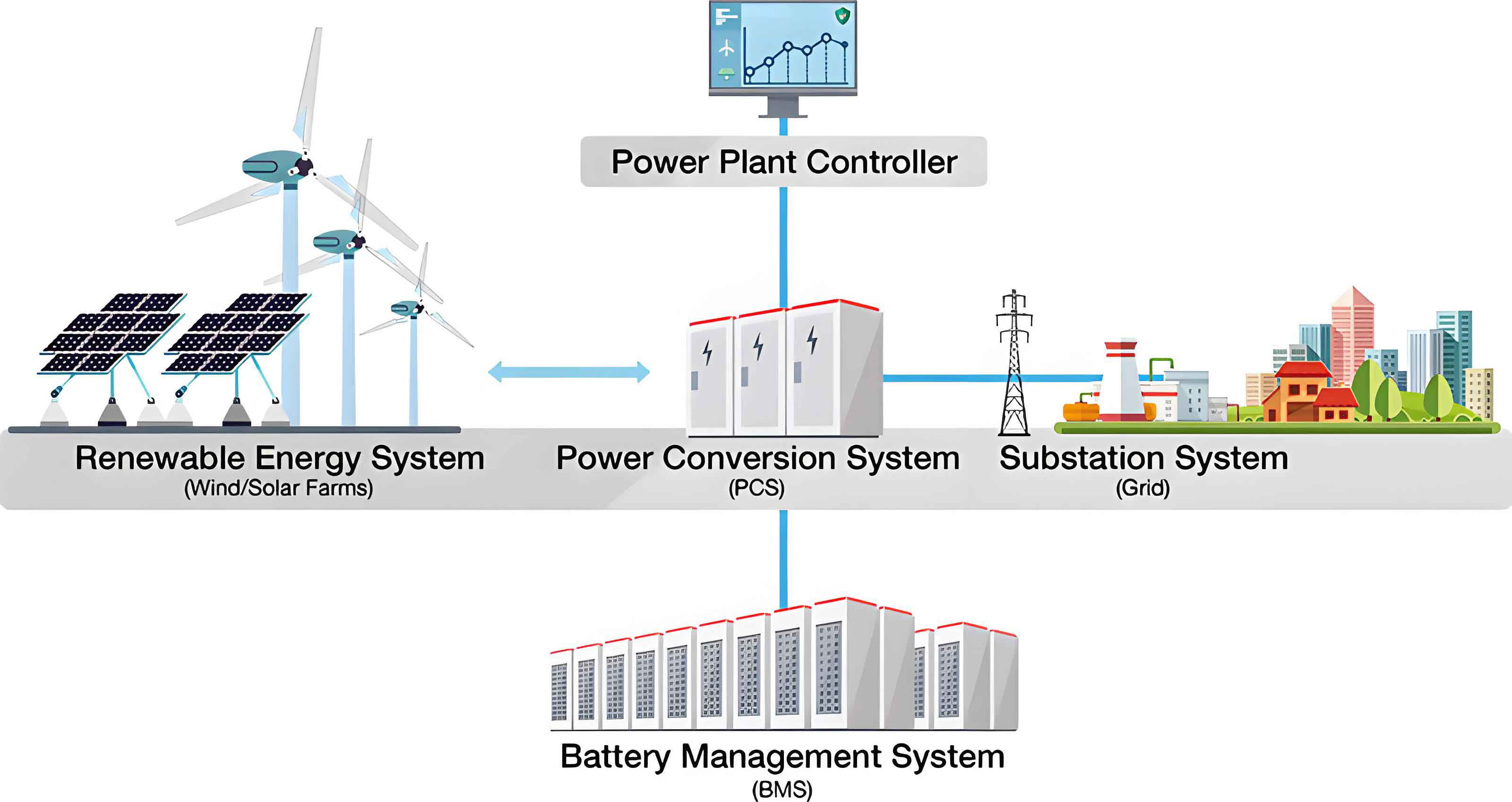
The continuous growth of energy production and consumption in China has revealed problems such as an unreasonable energy structure, low utilization efficiency, and a low proportion of renewable energy. By 2023, coal accounted for 55.3% of total energy consumption, fossil energy accounted for more than 80%, and non-fossil energy accounted for 17.5% of total energy consumption. Renewable energy has the advantages of low power generation cost and long-term energy development potential, and it contributes to the development of a low-carbon economy. However, renewable energy power generation, represented by wind power and photovoltaic power generation, has disadvantages such as intermittency, low stability, and low economy while exerting its advantages. In addition, with the continuous increase in electricity consumption, to ensure the stable operation of the power system, power supply departments need to plan power generation facilities according to the maximum demand during peak electricity consumption periods. The increase in the peak-valley difference of electricity consumption leads to long-term low-load operation of generator sets during off-peak periods, which reduces equipment efficiency and causes resource waste. Therefore, the development of energy storage technology is particularly important. Power energy storage systems contribute to the consumption of clean energy and improve the efficiency, stability, and economy of the power system.
Energy storage refers to the storage of energy in a medium over a period of time and the release of the energy for use when needed. The main purpose of energy storage is to bridge the gap between energy supply and demand, making energy production and use more stable and reliable. Energy storage can take many forms, including chemical energy storage (battery technology), mechanical energy storage (compressed air, flywheel technology, pumped hydro storage), electromagnetic energy storage (superconducting energy storage technology), and so forth. At present, compressed air energy storage and pumped hydro storage have been put into large-scale commercial operation. Energy storage technology is particularly important in the field of renewable energy, because the availability of renewable energy sources is influenced by factors such as weather, solar radiation, and wind speed. Energy storage can store surplus renewable energy for use under unfavorable conditions, thereby improving energy utilization efficiency and achieving sustainable energy development. Furthermore, energy storage is a key technology for future distributed energy systems and smart grids.
The compressed air energy storage system is a method of electrical energy storage and utilization. It mainly includes two stages: air compression and air expansion. During the compression stage, electrical energy is converted into compressed high-temperature and high-pressure air by compressors and stored in a high-pressure air storage tank after cooling. The heat generated during compression is stored in a heat storage water tank through heat exchange equipment. During the air expansion stage, the air in the storage tank is heated, and the high-pressure and high-temperature air drives the expander to perform work and generate electricity, thus realizing energy conversion. The compressed air energy storage system stores electrical energy through the air medium and releases the stored energy to generate electricity when needed. This technology can significantly improve the efficiency, safety, and economy of the power system. It is expected to provide an efficient energy storage and dispatching means for the power system to solve the problem of renewable energy fluctuation and improve the reliability and stability of the power system.
The expansion machine adopted in the energy release stage of the compressed air energy storage system is the expander, which is one of the key components of the energy storage system. According to the working principle, expanders can be divided into velocity-type expanders and positive-displacement expanders. Among them, velocity-type expanders, also known as turbine expanders, have the advantages of a more compact structure, better performance, and easier maintenance compared with positive-displacement expanders. Turbine expanders can be divided into axial-flow turbine expanders and radial-axial-flow turbine expanders (radial inflow turbine expanders) according to the direction of working fluid flow. Compared with traditional turbine expanders, the radial inflow turbine expander has higher efficiency and wider applicability. As the core power conversion component of the compressed air energy storage system, the performance of the radial inflow turbine expander directly affects the system efficiency and economy.
Existing studies mostly focus on the design of large-scale turbines, and there is still a lack of systematic exploration on the flow field characteristics and performance optimization of radial inflow turbine expanders for small-scale, high-speed compressed air energy storage systems. Therefore, carrying out research on the flow field characteristics and performance optimization of radial inflow turbine expanders is of great theoretical value and engineering significance for improving the comprehensive efficiency of energy storage systems and promoting the large-scale application of clean energy.
2. Aerodynamic Design and Flow Field Simulation of the Radial Inflow Turbine
2.1 Structural Form and Working Principle
The radial inflow turbine expander is a device that utilizes high-pressure gas expansion to generate mechanical energy. It is commonly used in energy storage systems, waste heat recovery, and refrigeration systems. Its structure mainly includes three parts: the volute casing, the guide vanes, and the rotor blades. The volute casing is the outer shell of the radial inflow turbine expander, and its main function is to uniformly distribute the incoming gas to the guide vanes. The design of the volute casing is important for the smooth inflow of gas; it needs to ensure that the gas can enter the guide vanes smoothly and avoid excessive vortices and pressure losses. The guide vanes, also known as nozzle cascades, function to convert the pressure energy of the gas into kinetic energy. When the high-pressure gas passes through the guide vanes, the velocity of the gas increases while the pressure decreases because of the shape of the guide vane passages. The rotor blades are the working impeller. After the gas flows out of the guide vanes, it impacts the rotor blades at high speed, causing the rotor to rotate and perform work, thereby converting the kinetic energy of the gas into mechanical energy.
Regarding the working principle of the radial inflow turbine expander, high-pressure air is released from the energy storage system. Air at a pressure \( P_0 \) and a temperature \( T_0 \) enters the volute casing of the radial inflow turbine expander through a pipeline. It enters the guide vanes through the volute passage, where it is uniformly distributed to each guide vane. In the guide vanes, the air expands and accelerates. In this process, the pressure decreases to \( P_1 \) because of the decrease in temperature to \( T_1 \). The high-speed gas after preliminary expansion in the guide vanes enters the rotor. The rotor is the core component of the radial inflow turbine expander. The gas continues to expand in the rotor, with the pressure further decreasing from \( P_1 \) to \( P_2 \) and the temperature decreasing from \( T_1 \) to \( T_2 \). In the rotor, the flow direction of the gas gradually changes from radial inflow to axial outflow. During this process, the kinetic energy and pressure energy of the gas are converted into mechanical energy through the rotation of the rotor. The rotation of the rotor transmits the mechanical energy to the generator through the shaft, and then the mechanical energy is converted into electrical energy. Since the pressure and temperature of the gas continuously decrease during the expansion process, the final discharged gas has relatively low pressure and temperature, which can be further utilized or discharged into the atmosphere.
2.2 One-Dimensional Thermodynamic Design
In the thermodynamic analysis of the radial inflow turbine expander in the compressed air energy storage system, to simplify the one-dimensional flow model, I assumed that the working fluid is an inviscid, adiabatic, ideal gas in steady flow. For the velocity triangle at the rotor inlet and outlet of the radial inflow turbine expander, the total torque expression of the working fluid is:
$$M = m_1 (D_1 C_{1u} – D_2 C_{2u})$$
where \( m_1 \) is the mass flow rate of the working fluid in kg/s, \( D_1 \) is the rotor inlet diameter in m, and \( D_2 \) is the rotor outlet diameter in m.
According to the relationship between torque and angular velocity, combined with the momentum change of the fluid in the turbine, the circumferential power expression of the unit-mass working fluid in the radial inflow turbine is:
$$N_u = \omega M = u_1 C_{1u} – u_2 C_{2u}$$
By using the orthogonal relationship of the components in the velocity triangle and the law of cosines, I can obtain:
$$2 u_1 C_{1u} = C_1^2 + u_1^2 – W_1^2$$
$$2 u_2 C_{2u} = C_2^2 + u_2^2 – W_2^2$$
Substituting these expressions into the circumferential power expression, I obtain:
$$N_u = \frac{u_1^2 – u_2^2}{2} + \frac{C_1^2 – C_2^2}{2} + \frac{W_2^2 – W_1^2}{2}$$
where \( u_1 \) and \( u_2 \) are the circumferential velocities at the rotor inlet and outlet, \( C_1 \) and \( C_2 \) are the absolute velocities at the rotor inlet and outlet, and \( W_1 \) and \( W_2 \) are the relative velocities at the rotor inlet and outlet.
Because the rotor inlet diameter of the radial inflow turbine differs from the outlet diameter (\( D_1 \neq D_2 \)), the centrifugal work term reduces to zero in axial-flow turbines. The difference in centrifugal work enables the radial inflow turbine to achieve higher effective work output under the same operating conditions, thus making it significantly superior to axial-flow turbines in terms of circumferential power performance.
The circumferential efficiency of the radial inflow turbine expander is expressed as:
$$\eta_u = \frac{u_1^2 – u_2^2 + C_1^2 – C_2^2 + W_2^2 – W_1^2}{2 H_s}$$
Based on the velocity triangles, the circumferential efficiency can be expressed as a function of multiple parameters:
$$\eta_u = f(u_1, \alpha_1, \beta_2, \Omega, \bar{D}_2)$$
where \( \alpha_1 \) is the absolute flow angle at the rotor inlet, \( \beta_2 \) is the relative flow angle at the rotor outlet, \( u_1 \) is the circumferential speed ratio, \( \Omega \) is the degree of reaction, and \( \bar{D}_2 \) is the diameter ratio (the ratio of the mean diameter at the rotor outlet to the rotor inlet diameter). Based on the above analysis, these seven variable parameters have a significant influence on the circumferential power and efficiency characteristics of the radial inflow turbine. Among them, the velocity coefficients of the guide vanes and rotor blades are mainly limited by the manufacturing process level. The other five variable parameters are key design parameters. In particular, the degree of reaction and the speed ratio have the greatest influence on the efficiency of the radial inflow turbine.
In this design, I ultimately selected the diameter ratio as 0.48, the speed ratio as 0.6, and the degree of reaction as \( \Omega = 0.49 \). For the flow angles, I selected \( \alpha_1 = 19.2^\circ \) and \( \beta_2 = 32.2^\circ \). According to the initial parameters of the radial inflow turbine expander selected for the compressed air energy storage system, I compiled a one-dimensional thermodynamic design program using programming software. The initial parameters are listed in the following table.
| Parameter | Value |
|---|---|
| Inlet temperature (K) | 353 |
| Inlet pressure (MPa) | 0.5 |
| Outlet pressure (MPa) | 0.15 |
| Mass flow rate (kg/s) | 0.5 |
| Degree of reaction | 0.49 |
| Speed ratio | 0.6 |
| Guide vane velocity coefficient | 0.96 |
| Rotor velocity coefficient | 0.80 |
| Rotor inlet absolute flow angle (deg) | 19.2 |
| Rotor outlet relative flow angle (deg) | 32.2 |
Through iterative calculation and verification, the final dimensional parameters of the radial inflow turbine expander are summarized in the following table.
| Parameter | Value |
|---|---|
| Isentropic expansion work (kJ/kg) | 103.2 |
| Rotor outer diameter (mm) | 104.1 |
| Rotor outlet outer diameter (mm) | 64.8 |
| Rotor outlet inner diameter (mm) | 28.1 |
| Number of rotor blades | 17 |
| Rotor inlet blade height (mm) | 3.9 |
| Rotor blade thickness (mm) | 1.2 |
| Radial clearance (mm) | 3.9 |
| Guide vane outlet diameter (mm) | 119.7 |
| Number of guide vanes | 26 |
| Rotor inlet Mach number | 0.92 |
| Gas dynamic efficiency | 78.51% |
2.3 Three-Dimensional Model Construction
Based on the dimensions obtained from the one-dimensional thermodynamic design, I established the three-dimensional model of the radial inflow turbine expander, including the rotor, guide vanes, and volute casing. A semi-open impeller structure was adopted for the rotor, with a radial-axial extending disc at the inlet side and an open outlet side. Compared with a traditional closed impeller, this structure has high gas dynamic efficiency, high structural strength, and strong adaptability. A convergent guide vane was selected because the flow at the guide vane outlet is subsonic. The flow passage cross-sectional area gradually decreases along the flow direction, which provides a simple structure, low machining cost, and low flow loss. The volute casing was modeled using rotating machinery modeling software, with a circular inlet and an arc transition at the tongue to reduce flow separation and impact losses and improve flow characteristics.
2.4 Numerical Simulation Setup
I used specialized turbomachinery meshing software to generate high-quality structured meshes for the full flow passages of the guide vanes and rotor. The near-wall mesh was refined to satisfy \( y^+ \leq 2 \) for the SST turbulent model. The volute mesh was generated with refinement at the volute outlet wall and the volute tongue wall, ensuring the mesh skewness was less than 0.9.
I performed a grid independence verification study on the full flow passage model. Eight groups of computational meshes were compared, with the total mesh count ranging from 3.12 million to 9.68 million. The isentropic efficiency variation curve showed that when the total mesh count reached 7.45 million, the isentropic efficiency change became small and stabilized. Therefore, the final selected total mesh count was 7.45 million, including 4.11 million cells for the rotor, 1.77 million for the guide vanes, and 1.57 million for the volute casing. The boundary conditions are listed in the following table.
| Boundary Condition | Type/Value |
|---|---|
| Inlet pressure (MPa) | 0.5 |
| Inlet temperature (K) | 353 |
| Outlet pressure (MPa) | 0.15 |
| Rotational speed (r/min) | 50000 |
| Working fluid | Air (ideal gas) |
| Inlet direction | Radial |
| Turbulence model | SST |
| Rotor-stator interface | Frozen rotor |
2.5 Comparison between Design Values and Simulation Values
The comparison between the numerical simulation results and the thermodynamic design results is summarized in the following table.
| Parameter | Design Result | Simulation Result | Relative Error (%) |
|---|---|---|---|
| Turbine inlet pressure (kPa) | 500 | 502.125 | +0.43 |
| Turbine inlet temperature (K) | 353 | 352.099 | -0.26 |
| Turbine outlet pressure (kPa) | 150 | 149.524 | -0.32 |
| Turbine outlet temperature (K) | 272.11 | 268.383 | -1.39 |
| Isentropic efficiency (%) | 78.51 | 81.07 | +3.20 |
The comparison shows that the relative errors between the designed values and simulated values are all within 4%, indicating that the thermodynamic design model is consistent with the three-dimensional numerical simulation model and the structure is reasonable.
2.6 Flow Field Analysis of the Complete Turbine
The pressure and temperature distributions of the radial inflow turbine expander show that the working fluid is uniformly distributed in the volute with no pressure drop or temperature drop. After entering the guide vanes, the working fluid experiences a pressure drop mainly at the oblique cut section of the guide vane suction surface. This is accompanied by a temperature decrease and velocity increase. After preliminary expansion in the guide vanes, the working fluid further expands in the rotor, forming a low-pressure region on the suction surface. The pressure on the pressure surface is greater than that on the suction surface, which drives the blades to rotate and perform work. A local low-pressure and low-temperature region exists on the suction surface of the rotor blades, which is related to the blade profile shape and requires further optimization. A local low-pressure region also exists at the trailing edge of the rotor blade outlet, mainly affected by wake losses. The pressure and temperature drops mainly occur in the oblique cut section of the guide vanes and the front half of the rotor, indicating that the expansion work is mainly performed in these regions.
The velocity streamlines of the radial inflow turbine expander show that the working fluid enters the guide vanes from the volute inlet, and the velocity streamlines are smooth and uniform in the volute, exhibiting axial symmetry. The streamlines in the guide vane region are relatively uniform, and the guiding effect of the guide vanes is good. After entering the rotor, the working fluid further accelerates, reaching the maximum at the blade throat. The acoustic power distribution indicates that the acoustic power level is relatively high in the guide vane outlet region and the rotor inlet region, indicating that these regions are the main noise sources, corresponding to the acceleration region of the working fluid.
3. Structural Parameter Optimization of the Radial Inflow Turbine
To improve the performance of the radial inflow turbine expander and reduce aerodynamic noise, I conducted numerical simulation studies on key structural parameters, including tip clearance, inlet blade angle, outlet blade angle, and blade leading edge structure, in the context of the compressed air energy storage system.
3.1 Influence of Tip Clearance
In the machining of the prototype of the radial inflow turbine expander, a certain tip clearance is required between the rotor blades and the shroud to prevent contact friction. An excessive tip clearance may lead to excessive gas leakage and thus reduce expansion efficiency. An excessively small tip clearance may cause the working fluid to flow poorly and increase noise and friction. I established two calculation schemes. In Scheme 1, I built models with no clearance and with equal radial and axial clearances (0.1-0.5 mm). In Scheme 2, I built models with unequal radial and axial clearances.
The simulation results show that at 30% blade height, the tip clearance has little influence on the flow field at the blade root. At 60% blade height, with increasing clearance, the vortex in the blade region first decreases and then increases. At clearances of 0.2 mm and 0.3 mm, the presence of the appropriate clearance facilitates smoother flow through the blade region, reducing flow separation and vortex generation. As the clearance becomes too large, gas flows from the pressure surface to the suction surface and mixes with the mainstream, generating vortices and affecting the flow field.
The influence of tip clearance on the performance of the radial inflow turbine expander in the compressed air energy storage system is as follows. When the radial and axial clearances are equal, the isentropic efficiency and output power gradually decrease with increasing tip clearance. From no clearance to 0.5 mm, the ratio of tip clearance to outlet blade height increases from 0% to 2.72%, the isentropic efficiency decreases from 81.07% to 80.00%, a decrease of 1.07 percentage points, i.e., for every 1% increase in the tip clearance/outlet blade height ratio, the isentropic efficiency decreases by 0.39%. The output power decreases from 54.12 kW to 51.86 kW, a decrease of 2.26 kW (4.18%), i.e., for every 1% increase in the tip clearance/outlet blade height ratio, the output power decreases by 1.54%.
When the axial and radial clearances are unequal, the simulation results are summarized in the following table.
| Case | Axial gap / inlet blade height (%) | Radial gap / outlet blade height (%) | Isentropic efficiency (%) | Efficiency change (%) | Output power (kW) | Power change (kW) | Power change (%) |
|---|---|---|---|---|---|---|---|
| 1 | 2.56 | 1.09 | 80.52 | – | 53.67 | – | – |
| 2 | 5.13 | 1.09 | 80.48 | -0.04 | 53.36 | -0.31 | 0.58 |
| 3 | 10.34 | 1.09 | 80.46 | -0.02 | 53.03 | -0.33 | 0.62 |
| 4 | 5.13 | 0.54 | 80.71 | – | 53.51 | – | – |
| 5 | 5.13 | 1.09 | 80.48 | -0.23 | 53.36 | -0.15 | 0.28 |
| 6 | 5.13 | 1.63 | 80.25 | -0.23 | 53.21 | -0.15 | 0.28 |
For every 1% increase in the axial clearance/inlet blade height ratio, the isentropic efficiency decreases by 0.0077 percentage points and the output power decreases by 0.15%. For every 1% increase in the radial clearance/outlet blade height ratio, the isentropic efficiency decreases by 0.42 percentage points and the output power decreases by 0.51%. This indicates that the radial clearance has a much greater influence on the performance of the radial inflow turbine expander than the axial clearance.
The exit aerodynamic noise of the radial inflow turbine expander in the compressed air energy storage system first decreases and then increases with increasing tip clearance. At a clearance of 0.2 mm, the noise is reduced by 1.1 dB compared with the no-clearance case. In the range of 0.2 mm to 0.5 mm, the noise increases with increasing clearance because excessive clearance increases fluid leakage and vortex intensity.
3.2 Influence of Inlet Blade Angle
I investigated inlet blade angles from 80° to 110° in increments of 5°, with additional fine increments of 1° between 90° and 100°. The velocity streamlines at 50% blade height show that at inlet blade angles from 80° to 94°, the streamlines are smooth. At angles from 95° to 110°, vortices appear at the blade bend, and at angles of 105° and 110°, the velocity at the blade inlet throat decreases and a high-velocity region appears on the inlet suction surface side.
The pressure distribution at 50% blade height shows that at inlet blade angles of 80° and 85°, the pressure on the pressure surface is lower than that on the suction surface at the blade leading edge, which opposes the rotation direction of the rotor and causes energy loss. At angles from 90° to 100°, the pressure on the pressure surface is greater than that on the suction surface, which helps drive the rotor to rotate and perform work. At angles of 105° and 110°, a local low-pressure region appears on the inlet suction surface, and the pressure difference between the two sides of the blade inlet increases.
The influence of the inlet blade angle on the performance of the radial inflow turbine expander is shown in the following table.
| Inlet blade angle (deg) | Isentropic efficiency (%) | Output power (kW) |
|---|---|---|
| 80 | 80.55 | 52.91 |
| 85 | 81.02 | 53.65 |
| 90 | 81.21 | 54.10 |
| 93 | 81.29 | 54.27 |
| 94 | 81.35 | 54.26 |
| 95 | 81.35 | 54.21 |
| 100 | 81.23 | 53.98 |
| 105 | 80.89 | 53.15 |
| 110 | 79.41 | 51.24 |
The isentropic efficiency reaches a peak value of 81.35% at inlet blade angles of 94° and 95°. The output power reaches a maximum value of 54.27 kW at an inlet blade angle of 93°. The rotor aerodynamic noise increases approximately linearly with increasing inlet blade angle. The exit aerodynamic noise remains relatively stable between 90° and 100°, but increases significantly at 110°. Considering all parameters comprehensively, an inlet blade angle of 93° provides a relatively stable flow field and an optimal balance between isentropic efficiency and output power in the compressed air energy storage system.
3.3 Influence of Outlet Blade Angle
I investigated outlet blade angles from 135° to 155° in increments of 5°, with additional fine increments of 1° between 140° and 150°. The velocity streamlines at 50% blade height show that from 135° to 145°, the vortex region at the blade bend gradually decreases and the streamlines become smoother. Above 145°, the velocity at the blade inlet throat decreases. At 155°, the streamlines become non-uniform, the velocity decreases significantly in most of the blade region, and the velocity increases significantly in the outlet region.
The pressure distribution shows that with increasing outlet blade angle, the local low-pressure region on the suction surface gradually decreases. In the range of 147° to 149°, the low-pressure region disappears and the pressure drop is uniformly distributed. At 155°, the pressure does not decrease in most of the blade region and is concentrated at the blade outlet, indicating uneven blade loading and low energy conversion efficiency.
The influence of the outlet blade angle on the performance of the radial inflow turbine expander is summarized in the following table.
| Outlet blade angle (deg) | Isentropic efficiency (%) | Output power (kW) | Total enthalpy drop (kJ/kg) |
|---|---|---|---|
| 135 | 79.69 | 53.38 | 115.2 |
| 140 | 81.63 | 54.69 | 117.8 |
| 141 | 82.15 | 54.92 | 118.6 |
| 142 | 82.67 | 55.34 | 119.3 |
| 143 | 83.19 | 55.71 | 120.1 |
| 144 | 83.71 | 56.13 | 120.9 |
| 145 | 84.23 | 56.49 | 121.7 |
| 146 | 84.68 | 56.81 | 122.4 |
| 147 | 85.02 | 56.72 | 123.1 |
| 148 | 85.31 | 56.61 | 123.8 |
| 149 | 85.15 | 56.12 | 123.2 |
| 150 | 84.52 | 55.43 | 121.9 |
| 155 | 77.06 | 46.22 | 107.6 |
The isentropic efficiency reaches a peak value of 85.31% at an outlet blade angle of 148°. The output power reaches a maximum value of 56.81 kW at an outlet blade angle of 146°. The exit aerodynamic noise first increases and then decreases with increasing outlet blade angle. The rotor aerodynamic noise remains initially stable and then gradually decreases. Considering all factors, an outlet blade angle of 148° provides the optimal flow field uniformity, the highest isentropic efficiency and total enthalpy drop, and relatively low aerodynamic noise for the compressed air energy storage system application.
3.4 Influence of Blade Leading Edge Structure
I optimized the original square blade leading edge to an elliptical arc leading edge with various leading edge curvature ratios (1 to 7). The velocity vector field shows that for the square leading edge, a notable flow disturbance occurs at the blade leading edge tip and the suction surface, forming flow separation, backflow, and vortices. After optimization to the elliptical arc leading edge, the streamlines become smoother, the flow separation disappears, and no backflow or vortex is observed.
The pressure distribution shows that the square leading edge has a local high-pressure region at the blade tip, with a sharp pressure gradient. As the leading edge curvature ratio increases, the high-pressure region shrinks and the pressure distribution becomes more uniform. The surface pressure distribution curves show that at the square leading edge, the pressure changes sharply near the stagnation point with clear inverse pressure gradients and fluctuations. For curvature ratios from 1 to 5, the pressure drop near the stagnation point decreases, and the inverse pressure gradient is reduced. At a curvature ratio of 4, the inverse pressure gradient becomes a positive gradient. From ratios 5 to 7, the pressure distribution is less affected by the curvature ratio.
The performance comparison before and after the leading edge optimization is shown in the following table.
| Leading edge type | Isentropic efficiency (%) | Efficiency change (%) | Output power (kW) | Power change (kW) | Power change (%) |
|---|---|---|---|---|---|
| Square leading edge | 84.71 | – | 55.68 | – | – |
| Elliptical arc leading edge (ratio 2) | 85.17 | +0.46 | 56.25 | +0.57 | +1.02 |
The influence of the leading edge curvature ratio on the performance of the radial inflow turbine expander is summarized below.
| Leading edge curvature ratio | Isentropic efficiency (%) | Output power (kW) |
|---|---|---|
| 1 | 84.98 | 55.89 |
| 2 | 85.17 | 56.25 |
| 3 | 85.32 | 56.48 |
| 4 | 85.45 | 56.61 |
| 5 | 85.51 | 56.73 |
| 6 | 85.48 | 56.65 |
| 7 | 85.44 | 56.57 |
The isentropic efficiency and output power reach their maximum values at a leading edge curvature ratio of 5. The leading edge curvature ratio has minimal influence on the exit aerodynamic noise. Based on comprehensive analysis, the elliptical arc leading edge with a curvature ratio of 5 provides the optimal performance and the most reasonable flow field distribution for the radial inflow turbine expander in the compressed air energy storage system.
4. Off-Design Performance Analysis of the Radial Inflow Turbine
The compressed air energy storage system faces various operating states in practice, and the radial inflow turbine expander operates under off-design conditions most of the time. I systematically analyzed the influence of inlet pressure (0.3 MPa to 1 MPa), inlet temperature (323 K to 393 K), and rotational speed (20000 r/min to 90000 r/min) on the performance of the radial inflow turbine expander through numerical simulation and explored the safe and stable operating boundary.
4.1 Influence of Inlet Temperature
With the rotational speed held constant at 50000 r/min, I studied three inlet pressure cases (0.4 MPa, 0.5 MPa, and 0.6 MPa) with inlet temperature varying from 323 K to 393 K. As the inlet temperature increases, the mass flow rate decreases for all three pressure cases due to the reduction in inlet gas density. From 323 K to 393 K, the mass flow rate decreases by 11.7%, 12.9%, and 13.8% for inlet pressures of 0.4 MPa, 0.5 MPa, and 0.6 MPa, respectively. The output power first increases and then slightly decreases. The peak power occurs near 363 K because the enthalpy drop increases with temperature, but this is gradually counteracted by the reduction in mass flow rate. The isentropic efficiency decreases approximately linearly with increasing inlet temperature. For every 10 K increase in inlet temperature, the isentropic efficiency decreases by approximately 0.42 to 0.47 percentage points depending on the inlet pressure. In general, the inlet temperature has a relatively small influence on the performance of the radial inflow turbine expander in the compressed air energy storage system, and the turbine can operate normally over a wide range of temperatures deviating from the design value.
4.2 Influence of Rotational Speed
With the inlet pressure held constant at 0.5 MPa, I studied three inlet temperature cases (333 K, 353 K, and 373 K) with rotational speed varying from 20000 r/min to 90000 r/min. The mass flow rate remains relatively stable from 20000 r/min to 60000 r/min, but decreases sharply above 60000 r/min due to flow blockage. At 90000 r/min, the mass flow rate decreases to 0.38 kg/s. The output power and isentropic efficiency first increase and then decrease with increasing rotational speed. At the design speed of 50000 r/min, the output power and efficiency reach their maximum values. At low speeds, the working fluid expands insufficiently, resulting in an output power of 23.5 kW and an efficiency of 48.8%. At excessive speeds, the flow blockage leads to an output power of 8.5 kW and an efficiency of 43.0%. The optimal operating speed range for the radial inflow turbine expander in the compressed air energy storage system is 50000 r/min to 60000 r/min.
4.3 Influence of Inlet Pressure
With the rotational speed held constant at 50000 r/min, I studied three inlet temperature cases (333 K, 353 K, and 373 K) with inlet pressure varying from 0.3 MPa to 1 MPa. The mass flow rate and output power increase linearly with increasing inlet pressure. For every 0.1 MPa increase in inlet pressure, the mass flow rate increases by 0.16 kg/s and the output power increases by 14.9 kW. The increase in mass flow rate is the main reason for the increase in output power. The isentropic efficiency decreases with increasing inlet pressure. For every 0.1 MPa increase in inlet pressure, the isentropic efficiency decreases by 1.42 percentage points. When the inlet pressure is lower than 0.9 MPa, the isentropic efficiency remains above 75%, and the turbine operates normally. The results are summarized in the following table.
| Operating parameter | Range studied | Performance trend | Recommended operating range |
|---|---|---|---|
| Inlet temperature (K) | 323 – 393 | Efficiency decreases by < 3.5%; power varies by < 1.1 kW | Wide range around 353 K |
| Rotational speed (r/min) | 20000 – 90000 | Efficiency peaks at design speed; sharp drop above 60000 | 50000 – 60000 |
| Inlet pressure (MPa) | 0.3 – 1.0 | Efficiency > 75% for pressure ≤ 0.9 MPa | 0.3 – 0.9 |
5. Experimental Study on the Influence of Inlet Pressure
I established an assembly model of the radial inflow turbine expander based on the simulation model, manufactured a prototype, and built an experimental platform to investigate the influence of inlet pressure on the performance of the radial inflow turbine expander in the compressed air energy storage system.
5.1 Experimental System
The experimental system consists of an air compression stage and an air expansion stage. The main equipment includes a screw air compressor (VW-0.2/30 type, with a motor power of 5.5 kW, an exhaust volume of 0.2 m³/min, and an exhaust pressure of 3.0 MPa), a carbon steel vertical air storage tank (with a design pressure of 4.2 MPa, a design temperature of 100°C, a hydrostatic test pressure of 5.25 MPa, and a volume of 1 m³), a heat storage buffer tank with a rated capacity of 60 L and a rated pressure of 0.6 MPa, the self-designed radial inflow turbine expander prototype, and a brazed plate heat exchanger (B3-60-38 type, with a design pressure of 3.0 MPa and a heat exchange area of 2.09 m²). The data acquisition system includes a MI-7016 data acquisition instrument, a JN-DN1 dynamic torque sensor (20 N·m), a magnetic powder brake (maximum torque 12 N·m) used as a load, a vortex flowmeter, and a FK-TH800 temperature transmitter.
The experimental procedure is as follows. I started the screw compressor to charge the air storage tank, turned on the circulating water pump to cool the compressed hot air, and completed the charging when the tank pressure reached 2 MPa. I set the sampling frequency, started the acquisition instrument, opened the ball valve at the outlet of the air storage tank, and adjusted the high-pressure reducing valve to the required pressure value while maintaining stability. I acquired the voltage signals of the inlet flow rate, torque, rotational speed, outlet temperature, and outlet pressure under set operating conditions, and converted them to parameter values according to the linear relationships. After data acquisition, I recharged the storage tank, adjusted to different pressure conditions, and repeated the procedure.
5.2 Experimental Results
The influence of inlet pressure on the mass flow rate of the radial inflow turbine expander is shown in the following table.
| Inlet pressure (MPa) | Stable flow rate (Nm³/h) |
|---|---|
| 0.3 | 310 |
| 0.4 | 370 |
| 0.5 | 440 |
During the startup process of the radial inflow turbine expander, the rotational speed and outlet temperature exhibit a stepwise change pattern with increasing flow rate. Under all three pressure conditions, the rotational speed and exit temperature exhibit three distinct step changes. When the flow rate reaches a certain value, a sudden increase in rotational speed is accompanied by a sudden drop in outlet temperature. The greater the inlet pressure, the more obvious the trends of temperature and rotational speed changes. The final stable values are shown in the following table.
| Inlet pressure (MPa) | Rotational speed (r/min) | Outlet temperature (K) |
|---|---|---|
| 0.3 | 6593 | 286.6 |
| 0.4 | 13225 | 283.5 |
| 0.5 | 16651 | 280.8 |
The influence of inlet pressure on the output power and outlet temperature of the radial inflow turbine expander is shown in the following table.
| Inlet pressure range (MPa) | Outlet temperature change (simulation, %) | Outlet temperature change (experiment, %) | Output power change (simulation, kW) | Output power change (experiment, kW) |
|---|---|---|---|---|
| 0.3 to 0.4 | -1.6 | -1.1 | +0.61 | +0.61 |
| 0.4 to 0.5 | -1.4 | -0.95 | +0.66 | +0.70 |
From 0.3 MPa to 0.5 MPa, the output power increases by 1.31 kW and the outlet temperature decreases by 5.8 K. The experimental values exhibit some deviation from the simulation values, mainly due to gas leakage in the mechanical seal, insufficient machining accuracy of the 3D-printed rotor blades, and the larger surface roughness of the blades, which increase flow resistance and cause additional energy losses. Despite the errors, the overall trend is consistent, indicating that the simulation model can accurately reflect the working characteristics of the radial inflow turbine expander in the compressed air energy storage system.
6. Conclusions
In this study, I designed a small radial inflow turbine expander suitable for a compressed air energy storage system. I numerically simulated its internal flow field, structural parameters, and performance under different operating conditions. I also fabricated a prototype and conducted experiments to study the influence of inlet pressure on the performance of the radial inflow turbine expander. The main conclusions are as follows:
(1) I developed a one-dimensional thermodynamic design program for the radial inflow turbine expander and established a parametric three-dimensional model. The errors between the one-dimensional thermodynamic calculation parameters and the numerical simulation results are within 4%, indicating that the thermodynamic design model is consistent with the three-dimensional numerical simulation model and the structure is reasonable. The overall flow field distribution of the radial inflow turbine expander is reasonable, with uniform expansion of the working fluid. The design-point isentropic efficiency is 81.07%. However, a local low-pressure region exists on the suction surface of the rotor blades, with a small range of flow separation, requiring further optimization.
(2) In terms of tip clearance, at 60% blade height, the vortex first decreases and then increases with increasing clearance. The exit aerodynamic noise first decreases and then increases. When the radial and axial clearances are equal, for every 1% increase in the tip clearance/outlet blade height ratio, the isentropic efficiency decreases by 0.39 percentage points and the output power decreases by 1.54%. When the radial and axial clearances are unequal, the radial clearance has a much greater influence on the performance of the radial inflow turbine expander than the axial clearance. The radial clearance/outlet blade height ratio increases by 1%, the isentropic efficiency decreases by 0.42 percentage points, while the axial clearance increases by 1%, the efficiency decreases by only 0.0077 percentage points.
(3) For the blade angles, an inlet blade angle that is too large or too small reduces the turbine efficiency and output power and causes uneven flow field distribution. At an inlet blade angle of 93°, the flow field is relatively stable and optimal. For the outlet blade angle, at 148°, the flow field uniformity is optimal, the isentropic efficiency and total enthalpy drop reach their peak values, and the aerodynamic noise is relatively low. The outlet blade angle has a more significant influence on the turbine performance and flow field than the inlet blade angle in the compressed air energy storage system.
(4) After optimizing the square blade leading edge to an elliptical arc leading edge, the flow separation on the blade pressure surface disappears. The isentropic efficiency increases by 0.46 percentage points, the output power increases by 1.02%, and the exit aerodynamic noise is significantly reduced. At a leading edge curvature ratio of 5, the inverse pressure gradient and flow separation disappear, the flow field distribution is the most reasonable, and the performance is optimal for the compressed air energy storage system.
(5) The off-design performance analysis shows that the inlet temperature has a relatively small influence on the performance of the radial inflow turbine expander. The turbine can operate normally over a wide range of temperatures deviating from the design value. The optimal operating speed range is 50000 r/min to 60000 r/min. When the inlet pressure is less than or equal to 0.9 MPa, the isentropic efficiency remains above 75%, and the turbine operates normally in the compressed air energy storage system.
(6) The experimental results show that the greater the inlet pressure, the greater the rate of change of the rotational speed and outlet temperature of the radial inflow turbine expander. At an inlet pressure of 0.3 MPa, the rotational speed is 6593 r/min and the outlet temperature is 286.6 K. At 0.4 MPa, the rotational speed is 13225 r/min and the outlet temperature is 283.5 K. At 0.5 MPa, the rotational speed is 16651 r/min and the outlet temperature is 280.8 K. Each sudden increase in rotational speed is accompanied by a decrease in outlet temperature. The greater the inlet pressure, the more obvious the trends of temperature and rotational speed changes. From 0.3 MPa to 0.5 MPa, the output power increases by 1.31 kW and the outlet temperature decreases by 5.8 K. The experimental values exhibit some deviation from the simulation values, mainly due to machining accuracy and sealing issues, but the overall trend is consistent, indicating that the simulation model can accurately reflect the working characteristics of the radial inflow turbine expander in the compressed air energy storage system.
For future work, the one-dimensional thermodynamic design can be further optimized using multi-objective optimization algorithms to obtain the optimal combination of variable parameters. The structural optimization should also consider the strength analysis of the radial inflow turbine expander. In addition, the machining accuracy and sealing performance of the prototype can be improved through optimized manufacturing processes and seal design. Further experiments should be conducted to study the influence of other operating parameters on the performance of the radial inflow turbine expander in the compressed air energy storage system, such as inlet temperature and rotational speed.