
In this thesis, I focus on the modeling, DC-side adaptive control, and AC-side adaptive control of a photovoltaic hybrid energy storage system. The rapid growth of renewable energy sources, especially photovoltaic generation, has introduced significant challenges to grid stability due to their inherent intermittency and randomness. To address these challenges, the energy storage system plays a vital role in smoothing power fluctuations and maintaining voltage stability. A hybrid energy storage system, combining energy-type storage such as batteries and power-type storage such as supercapacitors, can provide multi-timescale dynamic regulation. Based on this concept, I propose adaptive control strategies for both the DC bus and the AC side of the hybrid energy storage system, aiming at improving system robustness, power sharing accuracy, and power quality.
The research is motivated by the practical limitations of conventional control methods when applied to a photovoltaic hybrid energy storage system. Traditional droop control often ignores the variation of internal resistance and state of charge in storage units, leading to unbalanced power distribution and increased DC bus voltage deviation. On the AC side, conventional PQ control relies on fixed PI parameters and cannot effectively handle parameter uncertainties caused by source and load fluctuations. To overcome these drawbacks, I introduce adaptive mechanisms based on real-time state estimation and model reference adaptive control. The proposed methods are validated through extensive simulations under various operating conditions, proving their effectiveness in reducing voltage and current fluctuations while suppressing harmonics.
1. System Architecture and Modeling of Photovoltaic Hybrid Energy Storage System
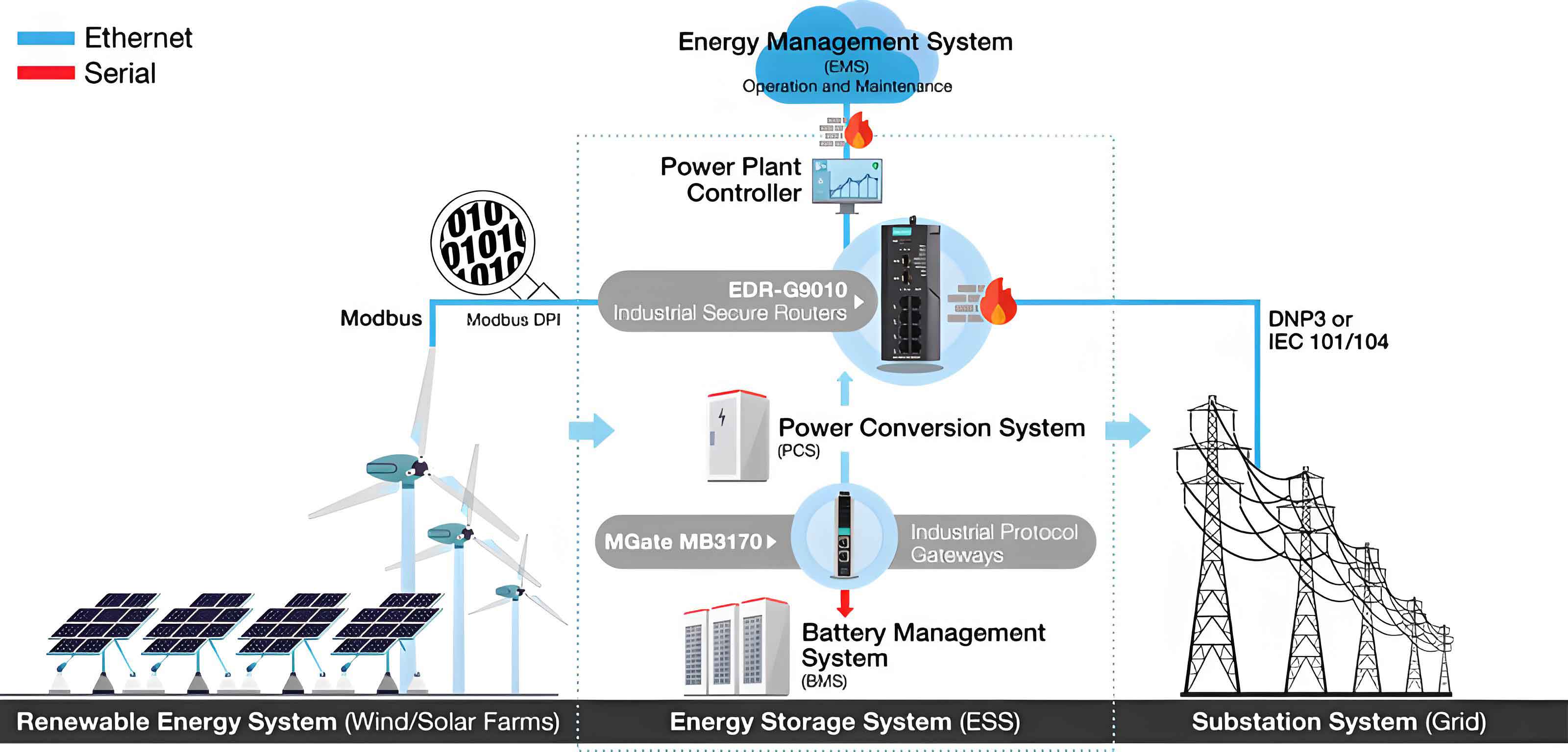
The topology of the photovoltaic hybrid energy storage system studied in this thesis is shown below. It comprises a photovoltaic array, a battery-supercapacitor hybrid energy storage system, bidirectional DC/DC converters, a bidirectional DC/AC inverter, LC filters, DC loads, and AC loads. The hybrid energy storage system is connected to the DC bus through the dual-parallel structure, where both the battery and the supercapacitor are interfaced by their own DC/DC converters. This structure enables independent control of each storage unit and maximizes the complementary advantages of different storage types. I selected this architecture because it allows precise power sharing and provides better stability under fluctuating source and load conditions.
For the photovoltaic generation model, I adopt the single-diode equivalent circuit. The output voltage of the photovoltaic array is expressed as:
$$ U_{PV}=i_s R_s – (i_d + i_{PV})R_s + i_{PV}R_{sh} $$
where $i_s$ is the photo-generated current, $i_d$ is the diode current, $R_s$ is the series resistance, $R_{sh}$ is the shunt resistance, and $i_{PV}$ is the output current. The P-U characteristics under different irradiance and temperature were analyzed. The maximum power point varies significantly with irradiance and temperature. Therefore, a maximum power point tracking algorithm is necessary to maintain operation at the peak power point.
The hybrid energy storage system consists of a battery and a supercapacitor. I analyzed four possible connection schemes: direct parallel, battery with DC/DC, supercapacitor with DC/DC, and dual-parallel. The dual-parallel structure was chosen because it allows independent control of both storage units. The battery is modeled as a voltage source in series with a variable resistor. The terminal voltage of the battery is:
$$ U_{bat}(t)=E_{bat}-i_{bat}(t)r_{bat}(t) $$
The state of charge of the battery is defined as:
$$ SOC_{bat}(t)=SOC_{bat}(0)-\int \frac{i_{bat}(t)}{C_{bat}}dt $$
The internal resistance of the battery depends on its SOC according to:
$$ r_{bat}(t)=r_{bat}^{min}+\frac{r_{bat}^{max}-r_{bat}^{min}}{1+e^{k(SOC-0.5)}} $$
Similarly, the supercapacitor is modeled as a voltage source with a small internal resistance. Its SOC is defined as:
$$ SOC_{sc}(t)=SOC_{sc}(0)-\int \frac{i_{sc}(t)}{C_{sc}}dt $$
The internal resistance of the supercapacitor is given by:
$$ r_{sc}=r_{base}(1+\alpha e^{-\beta SOC}) $$
The characteristics of the internal resistance curves show that the battery resistance changes strongly in the 20%-50% SOC range, while the supercapacitor resistance remains relatively stable. These models form the basis for the adaptive droop control developed in this thesis.
The bidirectional DC/DC converters are modeled using the state-space averaging method. The average model in continuous conduction mode is:
$$ \begin{cases} L\frac{di_{in}}{dt}+R_1 i_{in} = u_{in} – d_2 u_{out} \\ C\frac{du_{out}}{dt} = d_2 i_{in} – i_{out} \end{cases} $$
where $d_2$ is the duty cycle of the lower switch. For the bidirectional DC/AC inverter, the mathematical model in the synchronous rotating dq frame is:
$$ \begin{cases} u_d = Ri_d + L\frac{di_d}{dt} – \omega L i_q + e_d \\ u_q = Ri_q + L\frac{di_q}{dt} + \omega L i_d + e_q \end{cases} $$
The LC filter is essential for suppressing switching harmonics. Its state equations in the dq frame are:
$$ \begin{cases} C\frac{du_{Ld}}{dt} = i_d – i_{gd} \\ C\frac{du_{Lq}}{dt} = i_q – i_{gq} \\ L\frac{di_d}{dt} = u_{Ld} – e_d \\ L\frac{di_q}{dt} = u_{Lq} – e_q \end{cases} $$
Three types of loads are considered in this thesis: a pure resistive DC load, an impact DC load modeled as a separately excited DC motor, and a three-phase balanced AC load. The load models are used in the simulation to evaluate the control strategies under different disturbances.
| Storage type | Energy density (Wh/kg) | Power density (kW/kg) | Cycle life (thousand) | Response time | Efficiency (%) |
|---|---|---|---|---|---|
| Battery | 150-250 | 0.1-0.3 | 2-5 | ms | 90-95 |
| Supercapacitor | 5-15 | 10-100 | >500 | ms | 90-95 |
| Compressed air | 30-60 | 0.003-0.006 | >10 | min | 50-70 |
| Flywheel | 10-50 | 5-20 | >100 | ms | 85-90 |
| Superconducting | 0.5-5 | 100-500 | >1000 | μs | 95-98 |
In this thesis, the hybrid energy storage system combines a battery and a supercapacitor because of their complementary characteristics. The battery is suitable for absorbing/supplying low-frequency power fluctuations over long durations, while the supercapacitor handles high-frequency power pulses effectively. This combination enhances the overall performance and lifetime of the energy storage system.
2. Adaptive Droop Control for Hybrid Energy Storage System Based on Internal Resistance and State of Charge
The conventional droop control method applies a fixed droop coefficient to share power among storage units. However, the internal resistance of a battery or supercapacitor varies with its SOC. Ignoring this variation leads to unequal power sharing, over-charge/discharge of certain units, and increased DC bus voltage deviation. To solve this problem, I propose an adaptive droop control strategy that dynamically adjusts the droop coefficient according to the real-time internal resistance and SOC of each storage unit.
The P-U droop control equations for the battery and supercapacitor are:
$$ \begin{cases} u_{out1}=u_{bus}-k_{bat}P_1 \\ u_{out2}=u_{bus}-k_{sc}P_2 \end{cases} $$
where $k_{bat}$ and $k_{sc}$ are the droop coefficients. I set the droop coefficients inversely proportional to SOC and directly proportional to the internal resistance:
$$ \begin{cases} k_{bat}=\frac{r_{bat}}{SOC_{bat}} \\ k_{sc}=\frac{r_{sc}}{SOC_{sc}} \end{cases} $$
By substituting these coefficients into the droop equations, the power sharing relationship becomes:
$$ \frac{P_1}{P_2}=\frac{r_{sc}}{r_{bat}}\cdot \frac{SOC_{bat}}{SOC_{sc}} $$
This ensures that a storage unit with higher SOC and lower internal resistance absorbs or supplies more power, thereby preventing over-discharge/over-charge and achieving balanced SOC evolution.
However, the adaptive droop control with static virtual impedance still has a slow dynamic response when the operating point changes abruptly. To improve the dynamic behavior, I introduce a power compensation strategy based on the DC bus voltage fluctuation rate. The concept is to emulate a low-pass filter for the battery and a high-pass filter for the supercapacitor by using virtual inductance and virtual resistance, respectively. The battery current reference is generated through a virtual inductor:
$$ i_{out1}=\frac{U_{ref}-U_{out1}}{sL_U} $$
where $L_U$ is the virtual inductance. To adaptively adjust the virtual inductance, I define the voltage fluctuation rate over a sliding window T as:
$$ \Delta U_1 = \sqrt{\frac{1}{T}\int_{t-T}^{t}(U_{out1}-U_{bus})^2 dt} $$
The virtual inductance is then adjusted as:
$$ L_U = L_0 + k_L \Delta U_1 $$
where $k_L>0$. When the voltage fluctuation increases, the virtual inductance increases to smooth transient currents and protect the battery from high-frequency stress. Conversely, the supercapacitor uses a virtual resistor:
$$ i_{out2}=\frac{U_{ref}-U_{out2}}{R_U} $$
The virtual resistance is adjusted inversely to the voltage fluctuation rate:
$$ R_U = R_0 – k_R \Delta U_2 $$
with $k_R>0$ and the constraint $k_R\Delta U_2<1$. When the voltage fluctuation increases, the virtual resistance decreases, allowing the supercapacitor to respond faster and suppress high-frequency oscillations.
The combined effect of the virtual inductance and virtual resistance yields the following current distribution between the two storage units:
$$ G_1(s)=\frac{i_{out1}(s)}{i_{out}(s)}=\frac{1/R_U}{sL_U+1/R_U} $$
$$ G_2(s)=\frac{i_{out2}(s)}{i_{out}(s)}=\frac{sL_U}{sL_U+1/R_U} $$
Thus, $G_1(s)$ behaves as a first-order low-pass filter, while $G_2(s)$ behaves as a first-order high-pass filter. The crossover frequency is determined by:
$$ \omega_c = \frac{R_U}{L_U} $$
which varies adaptively with the voltage fluctuation rate. The Bode plot analysis confirms that the battery dominates the low-frequency band and the supercapacitor dominates the high-frequency band, matching the design objectives.
For stability analysis, I construct a Lyapunov function $V=\frac{1}{2}e^2$, where $e=U_{ref}-U_{out}$. The derivative is:
$$ \dot{V}=e\dot{e}=-e\, G_{dc}(s)e = -G_{dc}(s)e^2 $$
To ensure system stability, it is required that $\mathrm{Re}[G_{dc}(j\omega)]>0$ for all $\omega$. Numerical evaluation of the real part under various parameter values shows that this condition always holds, proving that the proposed adaptive control system is globally stable.
| Module | Parameter | Value |
|---|---|---|
| Photovoltaic | Rated voltage | 650 V |
| Short-circuit current | 25 A | |
| Temperature | 25°C | |
| Battery | Rated voltage | 700 V |
| Rated current | 20 A | |
| Initial SOC | 50% | |
| Supercapacitor | Rated voltage | 720 V |
| Rated current | 20 A | |
| Initial SOC | 50% | |
| DC/DC converter | Resistance | 5 Ω |
| Inductance | 2 mH | |
| Filter capacitance | 8 mF | |
| Resistive load | Resistance | 8 Ω |
| Impact load | Armature resistance | 0.5 Ω |
| Field resistance | 146 Ω |
Simulations were conducted on a photovoltaic hybrid energy storage system model built in Matlab/Simulink. Six operating conditions were tested: irradiance step-up, irradiance step-down, impact load connection, impact load disconnection, load reduction, and load increase. The DC bus voltage deviations under the proposed adaptive droop control are compared with those under the conventional droop control. The results are summarized below.
| Condition | Conventional droop | Adaptive droop | Improvement |
|---|---|---|---|
| Irradiance step-up | 3.7 | 2.6 | 29.7% |
| Irradiance step-down | 3.7 | 2.5 | 32.4% |
| Impact load connection | 34.3 | 22.9 | 33.2% |
| Impact load disconnection | 2.7 | 2.0 | 25.9% |
| Resistive load reduction | 9.8 | 7.0 | 28.6% |
| Resistive load increase | 7.3 | 5.6 | 23.3% |
The proposed method consistently reduces the DC bus voltage fluctuation compared with the conventional droop control. The improvement is most significant under the impact load connection scenario, where the voltage sag is reduced by 33.2%. These results demonstrate that the adaptive droop control based on internal resistance and SOC, combined with the voltage-fluctuation-based power compensation, effectively stabilizes the DC bus voltage in the hybrid energy storage system.
3. Model Reference Adaptive PQ Control Based on Local Parameter Optimal Gradient Method
On the AC side, the conventional PQ control scheme uses fixed PI controllers in the current loop. This approach is sensitive to parameter variations caused by source fluctuations and load disturbances. To improve the dynamic performance and robustness, I propose a model reference adaptive control (MRAC) scheme integrated into the PQ control structure. The adaptive law is derived using the local parameter optimal gradient method, also known as the MIT rule.
The overall control block is structured with three nested loops: power control, MRAC-based current control, and phase-locked loop. In the power control loop, the active power $P$ and reactive power $Q$ are decoupled by aligning the d-axis of the rotating frame with the grid voltage vector. Under this condition, $e_q=0$ and $e_d=E_{max}$. Therefore, the instantaneous active and reactive powers simplify to:
$$ \begin{cases} P=\frac{3}{2}E_{max}i_d \\ Q=-\frac{3}{2}E_{max}i_q \end{cases} $$
Hence, the d-axis current reference is proportional to the active power reference, and the q-axis current reference is proportional to the reactive power reference:
$$ \begin{cases} i_d^*=\frac{2P^*}{3E_{max}} \\ i_q^*=-\frac{2Q^*}{3E_{max}} \end{cases} $$
In the current loop, the plant is modeled as a first-order system:
$$ \theta_1 \frac{di_k}{dt}+ \theta_2 i_k = u_k $$
where $k=d,q$. The reference model is designed as a first-order system with a time constant $\tau$ corresponding to the desired bandwidth:
$$ \tau \frac{di_{m,k}}{dt}+ i_{m,k}= u_{m,k} $$
The bandwidth is selected between 0.1 and 0.2 times the switching frequency, and is further verified against the maximum modulation voltage. The adaptive mechanism adjusts the parameters $\theta_1$ and $\theta_2$ using the MIT rule to minimize the quadratic error between the plant output and the reference model output. Let $\varepsilon(t)=u_{m,k}(t)-u_{p,k}(t)$. The cost function is:
$$ J=\frac{1}{2}\int_{0}^{t} \varepsilon^2(\tau)d\tau $$
Applying the gradient descent method, the parameter update laws are:
$$ \frac{d\theta_1}{dt}=-\lambda \varepsilon \frac{\partial \varepsilon}{\partial \theta_1} = -\lambda \varepsilon \frac{\partial u_p}{\partial \theta_1} $$
$$ \frac{d\theta_2}{dt}=-\lambda \varepsilon \frac{\partial \varepsilon}{\partial \theta_2} = -\lambda \varepsilon \frac{\partial u_p}{\partial \theta_2} $$
From the plant model, the partial derivatives are:
$$ \frac{\partial u_p}{\partial \theta_1}=\frac{di_k}{dt}, \quad \frac{\partial u_p}{\partial \theta_2}=i_k $$
Thus, the adaptive laws become:
$$ \theta_1(t)=\theta_1(0)-\lambda \int_{0}^{t} \varepsilon \frac{di_k}{dt} d\tau $$
$$ \theta_2(t)=\theta_2(0)-\lambda \int_{0}^{t} \varepsilon i_k d\tau $$
The parameters are updated in real time so that the actual current closely tracks the reference model, even under source and load variations.
To address harmonic suppression, I analyze the conventional LC filter and its modified versions. The conventional LC filter has an undamped resonance peak that may cause oscillation. I compare two damping approaches: RC parallel and RC series in the capacitor branch. The transfer function of the conventional LC filter is:
$$ H(s)=\frac{1}{LCs^2+1} $$
For the RC parallel type, the transfer function becomes:
$$ H_{p}(s)=\frac{1}{LCs^2+\frac{L}{R}s+1} $$
For the RC series type, the transfer function becomes:
$$ H_{s}(s)=\frac{1}{LCs^2+RCs+1} $$
The Bode plot comparison shows that the RC series filter provides the most significant damping of the resonance peak and the fastest high-frequency attenuation. Therefore, I adopt the RC series LC filter in the proposed system.
For stability analysis of the adaptive current loop, I define a composite Lyapunov function that includes the tracking error and parameter errors:
$$ V=\frac{1}{2}\varepsilon^2+\frac{1}{2\lambda_1}(\theta_1-\theta_1^*)^2+\frac{1}{2\lambda_2}(\theta_2-\theta_2^*)^2 $$
Taking the derivative and substituting the adaptive law, I obtain:
$$ \dot{V} = -\frac{R}{L}\varepsilon^2 \le 0 $$
This proves that the system is globally asymptotically stable and the tracking error converges to zero.
| Module | Parameter | Value |
|---|---|---|
| DC/AC inverter | Modulation ratio | 0.9 |
| Switching frequency | 5 kHz | |
| LC filter | Inductance | 2 mH |
| Capacitance | 25 μF | |
| DC side | Voltage | 650 V |
| Capacitance | 20 F | |
| AC grid | Load resistance | 5 Ω |
| Load inductance | 2 mH | |
| Frequency | 50 Hz | |
| Line-to-line voltage | 380 V |
The AC-side simulations were carried out under six scenarios: photovoltaic irradiance step-down, step-up, DC load increase, DC load decrease, AC load decrease, and AC load increase. For each scenario, I compare the conventional PQ control and the proposed MRAC-based PQ control in terms of current transient overshoot and total harmonic distortion (THD).
| Condition | Conventional PQ | MRAC-based PQ | Improvement |
|---|---|---|---|
| PV irradiance step-down | 8.5 | 7.2 | 15.3% |
| PV irradiance step-up | 21.6 | 19.4 | 10.2% |
| DC load increase | 121.4 | 82.0 | 32.5% |
| DC load decrease | 81.8 | 50.5 | 38.3% |
| AC load decrease | 56.4 | 50.8 | 10.5% |
| AC load increase | 56.2 | 47.9 | 14.8% |
| Condition | Conventional PQ | MRAC-based PQ |
|---|---|---|
| PV irradiance step-down | 9.73 | 6.73 |
| PV irradiance step-up | 9.47 | 7.98 |
| DC load increase | 4.13 | 3.28 |
| DC load decrease | 9.54 | 7.88 |
| AC load decrease | 3.17 | 1.80 |
| AC load increase | 9.69 | 8.20 |
The simulation results show that the proposed MIT-based model reference adaptive PQ control significantly reduces current transients and THD values in all scenarios. In particular, under DC load increase, the current overshoot is reduced by 32.5%, and under DC load decrease, the improvement reaches 38.3%. The THD values are consistently lowered, especially in the case of AC load decrease, where the THD drops from 3.17% to 1.80%. These results confirm that the adaptive control scheme improves tracking accuracy and harmonic suppression capability of the photovoltaic hybrid energy storage system.
4. Conclusion
In this thesis, I presented a comprehensive research on adaptive control strategies for a photovoltaic hybrid energy storage system. The main contributions and conclusions are summarized below.
First, I established detailed mathematical models for each component of the photovoltaic hybrid energy storage system, including the photovoltaic array, battery, supercapacitor, bidirectional converters, LC filter, and various loads. The analysis of P-U curves and r-SOC characteristics provided the basis for developing adaptive control algorithms. The dual-parallel configuration of the hybrid energy storage system was selected to allow independent control of the battery and supercapacitor.
Second, on the DC side, I proposed an adaptive droop control strategy that incorporates the internal resistance and SOC of each storage unit into the droop coefficient. This strategy ensures rational power sharing and prevents over-charge/discharge. Furthermore, I introduced a voltage-fluctuation-based compensation mechanism using virtual inductance for the battery and virtual resistance for the supercapacitor, which emulates a low-pass/high-pass filter pair and improves dynamic response. Lyapunov stability analysis confirmed the global stability of the system. Simulation results across six operating conditions showed that the proposed method reduces DC bus voltage deviations by 23%-33% compared to conventional droop control.
Third, on the AC side, I developed a model reference adaptive PQ control based on the MIT rule. By adjusting the adaptive parameters online, the control loop can track the reference model accurately under source and load disturbances. The addition of a series resistor in the LC filter capacitor branch effectively damps resonance and suppresses high-order harmonics. The stability of the adaptive law was verified through a Lyapunov function. Simulations demonstrated that the proposed control reduces current transient overshoot by up to 38% and lowers THD significantly in all tested scenarios.
In conclusion, the adaptive control strategies proposed in this thesis substantially enhance the stability and power quality of the photovoltaic hybrid energy storage system. Future work may extend the methods to other renewable energy scenarios, e.g., wind-based hybrid energy storage systems, and consider more types of storage technologies, such as flywheels or compressed air energy storage. The findings provide a useful guideline for the design and operation of robust hybrid energy storage systems in modern power grids.