
In this work, I designed and implemented a comprehensive reactive power compensation solution for a distributed photovoltaic (PV) grid-connected system in an industrial park in Hubei Province, China. The project faced typical challenges such as poor power factor, voltage fluctuations, and harmonic pollution. My approach integrated advanced inverter control, hybrid compensation devices, and multi-timescale coordinated control. Through field verification, I demonstrated significant improvements in power quality and system stability. In this paper, I detail the technical architecture, key module designs, and engineering outcomes, with special emphasis on various types of solar inverter and their roles in reactive power support.
1. Project Background and Problem Analysis
The PV system in the industrial park has a total installed capacity of 5.36 MW, utilizing 21 string inverters (each 255 kW) and 21,000 monocrystalline silicon modules. The system connects to the 10 kV distribution network under a “self-consumption, surplus grid-feed” model. After commissioning, I observed three major issues:
- Power factor instability: During peak generation hours (noon), the power factor dropped to 0.75–0.85, below the grid requirement of 0.9, causing monthly penalty fees of approximately 23,000 CNY.
- Voltage fluctuation and harmonic distortion: Bus voltage varied by ±8%, and total harmonic distortion (THD) reached 7.2%, exceeding the 5% limit specified in GB/T 14549‑1993.
- Slow response of traditional compensation: The existing fixed capacitor bank (800 kvar) had a switching response time exceeding 40 ms, leading to a compensation blind zone and a power factor compliance rate of only 68%.
These problems arose from the limited reactive power capability of the inverters, the lack of dynamic coordination, and the presence of background harmonics from industrial loads. To address them, I developed a novel scheme centered on three pillars: inverter dynamic regulation, hybrid compensation (SVG + APF), and hierarchical coordinated control.
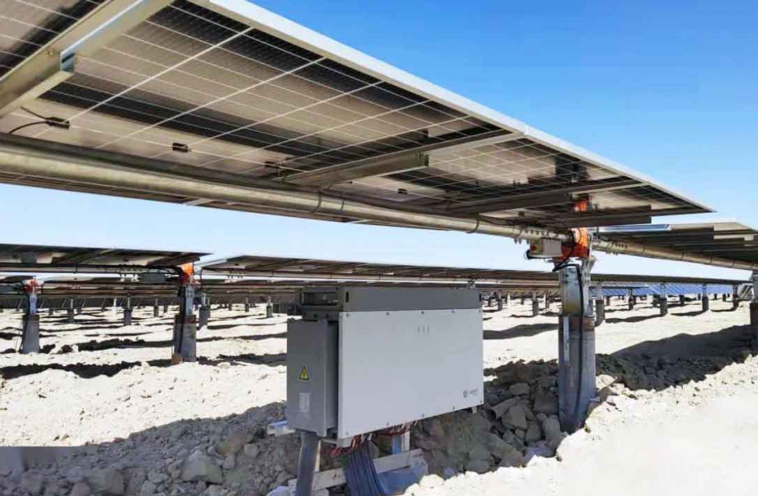
2. Overall Technical Architecture
I designed a three‑level architecture that combines the inherent reactive power capability of types of solar inverter with dedicated compensation equipment. The architecture consists of:
- Inverter dynamic regulation module: Each string inverter is upgraded to provide ±130 kvar of reactive power with a response time of 20 ms.
- Hybrid compensation device: A static var generator (SVG, ±1.5 Mvar) and an active power filter (APF, 300 A) work together for fast reactive power and harmonic mitigation.
- Multi‑timescale coordinated control: Three control layers (millisecond local, hundred‑millisecond predictive, and second‑level global optimization) ensure smooth coordination.
The system uses a real‑time data acquisition module (256 samples/cycle), a dynamic command allocation unit (10 ms cycle), and a priority matrix to avoid conflicts. The central controller communicates via IEC 61850 with a refresh cycle of 100 ms.
3. Inverter Dynamic Reactive Power Regulation Module
To solve the slow response and limited reactive range of the original inverters, I redesigned the control firmware and expanded the reactive power capability. The key design parameters are:
| Parameter | Original | After Upgrade |
|---|---|---|
| Power factor control range | ±0.95 | ±0.98 |
| Single inverter reactive capacity | ±85 kvar | ±130 kvar |
| Response time | 40 ms | 20 ms |
| Control hardware | DSP | FPGA |
The expanded capacity allows the inverter to handle the maximum fluctuation of ±121.8 kvar during noon. I implemented three operating modes that automatically switch based on system conditions:
- Dynamic compensation mode: Activated when PV power change rate exceeds ±45 kW/min. The inverter uses a phase‑locked loop (PLL) and discrete Fourier transform (DFT) algorithm to separate harmonics and inject reactive current.
- Steady‑state control mode: During stable periods, the inverter operates in constant power factor mode (0.95 ± 0.02) using a PI controller.
- Voltage support mode: When the grid voltage deviates by more than ±3%, the inverter switches to constant voltage control, limiting the voltage step to ≤0.5 kV.
These enhancements make the inverter a highly responsive reactive power source, demonstrating one of the most flexible types of solar inverter in distributed systems. The FPGA‑based control platform reduces the control cycle and improves anti‑interference performance.
4. Hybrid Compensation Device Design
4.1 Static Var Generator (SVG)
I selected a ±1.5 Mvar bidirectional SVG with a cascaded H‑bridge topology. The SVG provides 1.2 Mvar capacitive support for transmission line losses and 804 kvar inductive capacity for sudden PV output drops. Each phase consists of 28 submodules (2,400 V per module) plus 2 redundant modules for reliability. The dynamic response time is ≤20 ms.
4.2 Active Power Filter (APF) and Passive Filters
To reduce THD from 7.2% to below 5%, I designed a three‑channel APF with a total capacity of 300 A. The APF uses adaptive spectrum analysis to identify and mitigate 2nd to 50th harmonics, with priority given to 11th, 13th, 23rd, and 25th orders. Additionally, I installed 5th and 7th passive filter banks (200 kvar each, quality factor Q=50) to suppress background harmonics from nearby industrial drives.
4.3 Coordination Logic
I defined a priority matrix: the SVG handles fundamental reactive power compensation, while the APF focuses on harmonics. A dead zone of 50 kvar prevents overlapping responses under light load conditions. The hybrid configuration ensures that both types of solar inverter and external compensation work seamlessly together.
5. Multi‑Timescale Coordinated Control
I developed a three‑layer control framework to handle rapid transients and long‑term trends. The layers are summarized in the table below:
| Control Layer | Time Scale | Scope | Algorithm |
|---|---|---|---|
| Local (inverter) | Millisecond (≤20 ms) | ±50 kvar fine adjustments | Sliding mode control |
| Medium (SVG) | Hundred‑millisecond (100 ms) | ±200 kvar medium adjustments | Simplified neural network prediction |
| Global (central controller) | Second (5 s refresh) | Allocation of SVG/APF/inverter setpoints | Genetic algorithm optimization |
The local layer responds to fast power factor fluctuations using sliding mode control. The medium layer predicts reactive demand based on the last 5 seconds of data, pre‑activating the SVG. The global layer optimizes the distribution among all devices, considering voltage stability, THD priority, and SVG load margin. Communication follows IEC 61850 with a primary‑backup dual channel (Modbus TCP as backup) to ensure reliability.
6. Protection and Monitoring System
To guarantee safe operation, I implemented several protective mechanisms:
- Overvoltage protection: If bus voltage exceeds 110% of rated value, the SVG capacitive output is blocked within 30 ms.
- Harmonic lock‑out: When THD exceeds 7.5%, the inverter reactive output is locked and the APF enters high‑efficiency harmonic absorption mode.
- Soft‑start circuit: The main contactor closes only when bus voltage reaches ≥90% of rated value, preventing capacitor inrush.
A 16‑channel power quality monitoring terminal continuously records six key metrics: voltage deviation, frequency fluctuation, harmonic content, flicker, current distortion, and power factor. Data is stored for three years and accessible via a web platform for trend analysis.
7. Engineering Application and Performance Evaluation
I deployed the complete solution at the industrial park site. The installation involved upgrading the firmware of all 21 string inverters, commissioning the SVG/APF hybrid system, and integrating the control layers. After three months of operation, I collected and analyzed performance data. The results are shown in the tables below.
| Metric | Before | After |
|---|---|---|
| Average power factor (noon peak) | 0.81 | 0.94 |
| Power factor compliance rate | 68% | 97.6% |
| Monthly penalty (CNY) | 23,000 | 2,000 |
| Metric | Before | After | Standard Limit |
|---|---|---|---|
| Bus voltage fluctuation | ±8% | ±2.5% | ±7% (GB/T 12325‑2008) |
| Total harmonic distortion (THD) | 7.2% | 2.6% | 5% (GB/T 14549‑1993) |
| 11th harmonic reduction | – | 68.4% | – |
| 13th harmonic reduction | – | 73.1% | – |
| Component | Before (ms) | After (ms) |
|---|---|---|
| Inverter reactive response time | 40 | 20 |
| SVG dynamic response time | N/A | 18 |
| Hybrid system coordination success rate | – | 92% |
I also estimated mathematical models to quantify the improvements. The power factor after compensation can be expressed by the reactive power balance equation:
$$ Q_{\text{total}} = Q_{\text{load}} – (Q_{\text{inv}} + Q_{\text{SVG}} + Q_{\text{APF}}) $$
where \( Q_{\text{inv}} \) is the inverter reactive output, \( Q_{\text{SVG}} \) is the SVG reactive contribution, and \( Q_{\text{APF}} \) includes fundamental reactive from the APF. With the new system, \( Q_{\text{total}} \) is maintained near zero, resulting in a power factor above 0.94.
For harmonic mitigation, the THD reduction is described by:
$$ \mathrm{THD}_{\text{after}} = \sqrt{\frac{\sum_{h=2}^{50} (I_h – \Delta I_h)^2}{I_1^2}} $$
where \( \Delta I_h \) is the harmonic current cancelled by the APF and passive filters. The adaptive algorithm identifies the dominant harmonics and achieves over 70% cancellation for the 11th and 13th orders.
The economic benefit is substantial: the annual penalty saving of 27,000 CNY contributes to a payback period of less than 3 years for the compensation equipment. Moreover, the improved power quality reduces wear on sensitive industrial equipment.
8. Conclusion
I have successfully designed and applied a reactive power compensation scheme for a distributed PV grid-connected system. By combining dynamic inverter regulation (leveraging the flexibility of types of solar inverter), a hybrid SVG/APF compensator, and a multi‑timescale control architecture, I achieved a power factor compliance rate of 97.6%, voltage fluctuation within ±2.5%, and THD below 2.6%. The system responds within 20 ms to rapid changes, eliminating compensation blind zones. This work demonstrates that a well‑coordinated approach, considering both inverter-based and external compensation, can significantly enhance the grid integration of distributed PV. The solution is scalable and can be replicated in other industrial parks with similar challenges. Future work may explore machine learning for further optimization of reactive power dispatch among different types of solar inverter and grid constraints.