
In the context of modern power systems, battery energy storage systems (BESS) play an indispensable role in mitigating the intermittent power fluctuations from renewable energy sources, such as wind and solar. The modular multilevel converter (MMC) has become one of the most promising topologies for integrating large-scale battery energy storage systems (BESS) due to its scalability, modularity, and high-voltage capability. However, a critical challenge arises from the submodule (SM) capacitors within the MMC, which must suppress fundamental and double-frequency power ripples. These low-frequency power fluctuations necessitate large capacitance values, significantly increasing the volume, weight, and cost of the overall system. In traditional MMC systems, SM capacitors account for more than 50% of the total volume and weight. My analysis further reveals that for MMC-based battery energy storage systems (BESS), the required capacitance can be up to 1.7 times that of a conventional MMC, exacerbating the problem.
To address this issue, I propose a compact MMC-based battery energy storage system (BESS) architecture that dramatically reduces the required SM capacitance. The key innovation is the use of a bidirectional three-port converter (BTPC) that transfers low-frequency power from the SM capacitors to a common low-voltage DC (LVDC) bus. By aggregating all low-frequency power from different arms and phases, these power components cancel out at the common bus, leaving only DC power. Consequently, the SM capacitors need only to filter high-frequency switching ripples, allowing a 99% reduction in capacitance—from 10 mF down to 100 μF—without increasing the bus capacitance. In this work, I will detail the power fluctuation analysis, compare different topologies, derive the low-frequency power elimination (LFPE) control strategy based on impedance analysis, and validate the system through experimental results.
Power Fluctuation Analysis of MMC-Based Battery Energy Storage Systems
I first analyze the instantaneous power in a conventional MMC and compare it with that of an MMC-based battery energy storage system (BESS). Consider an MMC with a total DC-link voltage Vdc, modulation index m, and grid angular frequency ω. The AC output voltage and current are:
$$
v_o = \frac{1}{2} m V_{dc} \sin(\omega t)
$$
$$
i_o = I_o \sin(\omega t – \phi)
$$
For the upper arm of phase A in an MMC-based battery energy storage system (BESS), each SM voltage and current are:
$$
v_{SMu} = \frac{V_{dc}}{2N} (1 – m \sin \omega t)
$$
$$
i_{SMu} = 0.5 I_o \sin(\omega t – \phi)
$$
The instantaneous output power of a single SM in the upper arm is:
$$
p_{SMu} = v_{SMu} i_{SMu} = P_0 – 0.5 m P_{map} \sin(\omega t – \theta) – 0.5 m P_{map} \cos(2\omega t – \phi – \theta)
$$
Where:
$$
P_0 = \frac{V_{dc} I_o}{4N} \cos \phi, \quad P_{map} = \frac{V_{dc} I_o}{4N}, \quad \theta = \arctan(\frac{\cdots}{\cdots})
$$
For a conventional MMC (without integrated battery storage), the SM current also includes a DC component from the DC bus. The upper arm SM current becomes:
$$
i_{SMut} = 0.5 I_o [\sin(\omega t – \phi) + 0.5 m \cos \phi]
$$
The corresponding instantaneous power is:
$$
p_{SMut} = P_{map}[(0.5m^2 – 1)\cos \phi \sin \omega t – \sin \phi \cos \omega t – 0.5 m \cos(2\omega t – \phi)]
$$
| Component | MMC-BESS | Traditional MMC |
|---|---|---|
| DC | 0.4 Pmap | 0 |
| Fundamental (ω) | Pmap | 0.68 Pmap |
| Double-frequency (2ω) | 0.4 Pmap | 0.4 Pmap |
To quantify the power fluctuation severity, I define the power fluctuation factor kPflu as the RMS of the AC power component normalized by the peak power amplitude Pmap:
$$
k_{Pflu} = \frac{1}{P_{map}} \sqrt{\frac{1}{T} \int_0^T |p_{SMu\_AC}(t)|^2 dt}
$$
By evaluating kPflu for different m and φ, I find that the worst-case ratio between the MMC-based battery energy storage system (BESS) and the conventional MMC is 1.70 (at m=1, φ=0). This demonstrates that MMC-based battery energy storage systems (BESS) require approximately 1.7 times larger SM capacitance than traditional MMCs.
Proposed Compact MMC-BESS Architecture
The core idea of my proposed compact MMC-based battery energy storage system (BESS) is to channel the low-frequency power from every SM to a common low-voltage DC (LVDC) bus through the bidirectional three-port converter (BTPC). The instantaneous powers of all six arms (three phases, upper and lower) are:
$$
\begin{aligned}
p_{SMAu} &= P_0 – 0.5 m P_{map} \sin(\omega t – \theta) – 0.5 m P_{map} \cos(2\omega t – \phi – \theta)\\
p_{SMAl} &= P_0 + 0.5 m P_{map} \sin(\omega t – \theta) – 0.5 m P_{map} \cos(2\omega t – \phi – \theta)\\
p_{SMBu} &= P_0 – 0.5 m P_{map} \sin(\omega t – \frac{2\pi}{3} – \theta) – 0.5 m P_{map} \cos(2\omega t – \frac{2\pi}{3} – \phi – \theta)\\
p_{SMBl} &= P_0 + 0.5 m P_{map} \sin(\omega t – \frac{2\pi}{3} – \theta) – 0.5 m P_{map} \cos(2\omega t – \frac{2\pi}{3} – \phi – \theta)\\
p_{SMCu} &= P_0 – 0.5 m P_{map} \sin(\omega t + \frac{2\pi}{3} – \theta) – 0.5 m P_{map} \cos(2\omega t + \frac{2\pi}{3} – \phi – \theta)\\
p_{SMCl} &= P_0 + 0.5 m P_{map} \sin(\omega t + \frac{2\pi}{3} – \theta) – 0.5 m P_{map} \cos(2\omega t + \frac{2\pi}{3} – \phi – \theta)
\end{aligned}
$$
When all these instantaneous powers are summed at the common LVDC bus through the BTPC network:
$$
P_{sum} = \sum_{i \in \{Au,Al,Bu,Bl,Cu,Cl\}} p_{SM,i} = 6P_0 = \frac{3}{2} \frac{V_{dc} I_o}{N} \cos \phi
$$
Remarkably, all fundamental and double-frequency terms cancel out, leaving only a constant DC power. This cancellation happens because the three phases are symmetrically balanced. Therefore, the LVDC bus only handles DC power, and no additional large capacitors are needed to absorb low-frequency ripples. The SM capacitors, in turn, only need to suppress high-frequency switching noise (typically 10 kHz or higher), allowing a drastic reduction in capacitance—by up to 99% (e.g., from 10 mF to 100 μF).
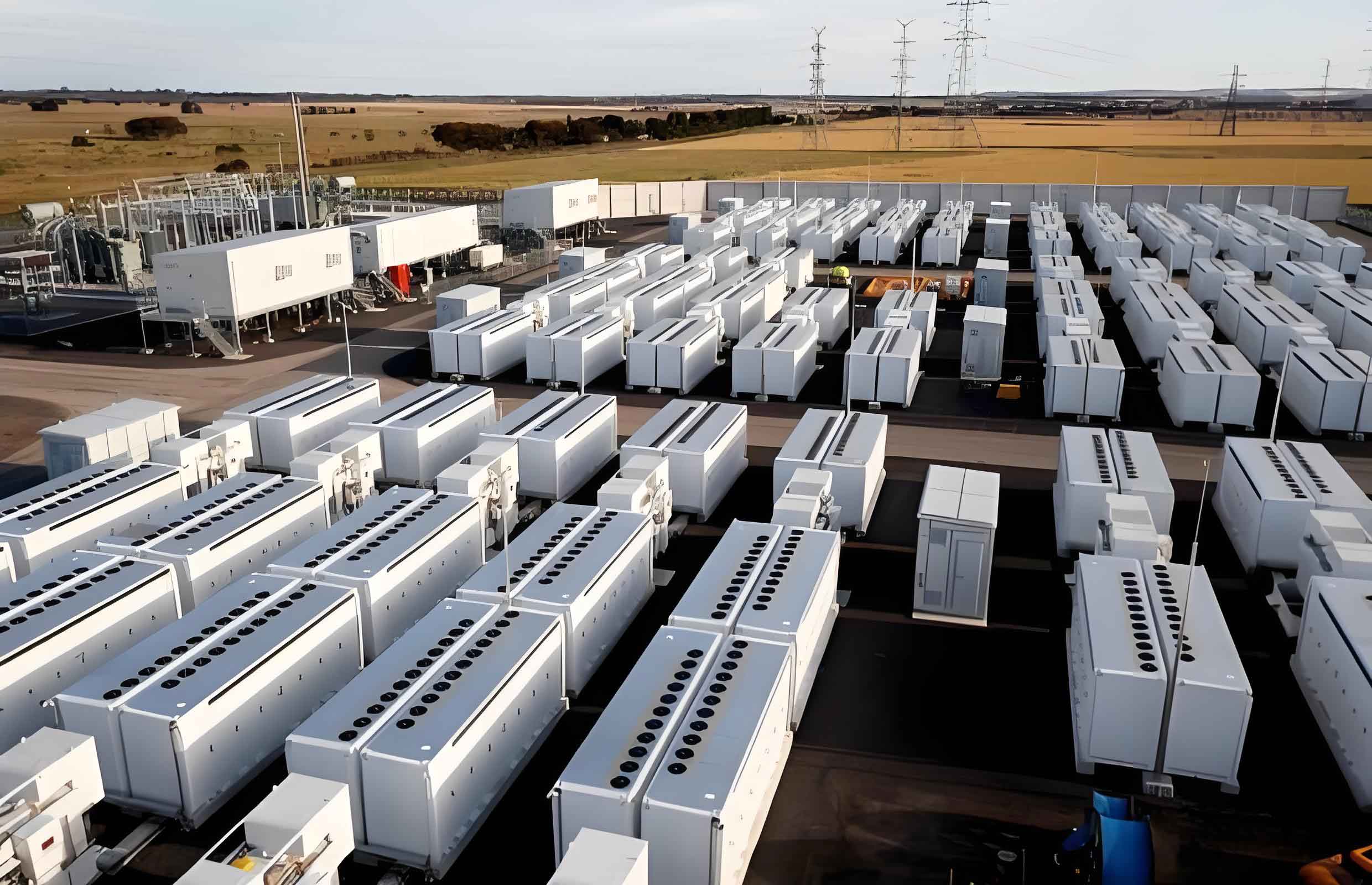
I insert the figure illustrating the compact MMC-based BESS architecture here.
Comparison of Different Low-Frequency Power Elimination Topologies
Several approaches exist to eliminate low-frequency power ripples in power converters. I compare my proposed BTPC-based solution with conventional external converter schemes, such as Buck/Boost with an additional large capacitor, and Dual Active Bridge (DAB) with a battery. The comparison covers switch count, safety, reliability, and current stress. Table 2 summarizes the results.
| Criteria | BTPC | Buck/Boost + Large Cap | DAB + Battery |
|---|---|---|---|
| Number of switches | 8K | 2K | 8K |
| Safety | High | High | Low |
| Reliability | High | Low to Medium* | Low |
| Current stress (pu) | 1.87 | 2.58 | 2.58 |
* Depends on the type of capacitor used (electrolytic vs. film).
The current stress factor is derived as the RMS current ratio when the converter transmits both DC and low-frequency power (BTPC) versus only DC power (external converters with separate low-frequency compensator). For BTPC, the RMS current increases by a factor:
$$
K_{1RMSI} = \sqrt{\frac{\int_0^{2\pi} (p_{SMu}(t))^2 d(\omega t)}{(0.5 m P_{map})^2}} = 1.87 \quad (\text{at } m=1, \phi=0)
$$
For the external scheme (e.g., Buck/Boost + large capacitor), the compensator handles only the AC component, and its RMS current is:
$$
K_{2RMSI} = \sqrt{\frac{\int_0^{2\pi} (p_{SMu\_AC}(t))^2 d(\omega t)}{(0.5 m P_{map})^2}} = 1.58
$$
However, the total current stress considering both the main converter and the compensator is 1 + 1.58 = 2.58 pu, which is higher than the 1.87 pu of the integrated BTPC. Therefore, my proposed BTPC topology achieves lower conduction losses and thermal stress.
Low-Frequency Power Elimination (LFPE) Control Strategy
To enable the BTPC to supply the required low-frequency current to the MMC, I must design a control strategy that minimizes the BTPC’s output impedance at the fundamental and double frequencies. As shown in Fig. 4 (conceptual), the BTPC and the SM capacitor CSM are connected in parallel. The current sharing between them is determined by their impedance magnitudes at the ripple frequencies. Ideally, |ZB(jω)| << |ZC(jω)| at ω = ω0 and 2ω0.
Using a single voltage control loop (as in literature), the closed-loop BTPC impedance is:
$$
Z_{B\_c}(s) = \frac{Z_{B\_o}(s)}{1 + \frac{Z_{B\_o}(s)}{Z_C(s)} + T_v(s)}
$$
where Tv(s) is the loop gain. Since the voltage reference is DC, Tv at 50 Hz and 100 Hz is limited when using a PI controller, resulting in insufficient reduction of ZB\_c. To overcome this, I introduce a current feedback loop that directly senses the low-frequency current flowing into the SM capacitor (iMMC – iBTPC) and feeds it through a low-pass filter and a dual quasi-proportional-resonant (dQPR) controller. The new closed-loop BTPC impedance under LFPE control is:
$$
Z_{B\_cn}(s) = \frac{Z_{B\_o}(s) + sC_{SM} Z_{B\_o}(s) G_{LPF}(s) – G_{LPF}(s) Z_{B\_o}(s)}{1 + T_v(s) + \frac{Z_{B\_o}(s)}{Z_C(s)} (1 + T_v(s) + G_{LPF}(s))}
$$
At the resonant frequencies, the dQPR controller provides high gain, making the denominator very large, thus ZB\_cn becomes much smaller than ZC. Consequently, almost all low-frequency current flows through the BTPC, and the SM capacitor experiences negligible low-frequency voltage ripple. The dQPR controller transfer function is:
$$
G_{dQPR}(s) = k_{p0} + \frac{2k_{r1}\omega_{c1}s}{s^2 + 2\omega_{c1}s + \omega_0^2} + \frac{2k_{r2}\omega_{c2}s}{s^2 + 2\omega_{c2}s + (2\omega_0)^2}
$$
where kp0, kr1, kr2 are gains, and ωc1, ωc2 are cutoff frequencies. The overall LFPE control structure is shown in the block diagram. A PI regulator maintains the average SM voltage at 50 V, while the dQPR loop cancels the low-frequency ripples.
Experimental Validation
I constructed a single-phase three-level MMC-based battery energy storage system (BESS) prototype to verify the proposed architecture and control. The system parameters are listed in Table 3.
| Component | Parameter | Value |
|---|---|---|
| MMC | Number of SMs per arm, N | 2 |
| SM capacitance, Cui/Cli | 100 μF | |
| SM capacitor voltage reference | 50 V | |
| Arm inductance, L | 5 mH | |
| Fundamental frequency | 50 Hz | |
| MVDC bus voltage | 100 V | |
| BTPC | Input inductance L1, L2 | 1 mH |
| BTPC inductance Lf | 40 μH | |
| Transformer turns ratio, n | 1:1 | |
| LVDC bus capacitance | 200 μF |
System Function Verification
Initially, the MMC AC side was connected to an 8 Ω load (100 W). At time t0, the load was switched to 2 Ω (400 W). Figure 9 (conceptual) shows the SM capacitor voltages (vSM1–vSM4). After the load step, the voltage ripples increased slightly but remained within 4.8 V peak-to-peak, and the average voltage stayed at 50 V. The AC output voltage and current waveforms remained nearly sinusoidal, with peak current changing from 5 A to 20 A. The currents iBTPC and iMMC both increased proportionally, maintaining cancellation and keeping the SM capacitor voltage ripple low.
Effect of Capacitance Value
I tested three different SM capacitance values: 50 μF, 100 μF, and 200 μF. Table 4 summarizes the observed peak-to-peak voltage ripple at full load (400 W).
| CSM (μF) | Peak-to-Peak Ripple (V) | Ripple Percentage (%) |
|---|---|---|
| 50 | 11.8 | 23.6 |
| 100 | 4.8 | 9.6 |
| 200 | 3.1 | 6.2 |
The 100 μF capacitor easily achieves a ripple below 10%, whereas 50 μF leads to excessive ripple. Increasing to 200 μF provides only marginal improvement. Hence, 100 μF is the optimal choice, representing a 99% reduction from the conventional 10 mF.
Comparison with Single Voltage Control
To highlight the benefit of the proposed LFPE control, I switched from LFPE to single voltage control at the same operating point (400 W, CSM=100 μF). Under single voltage control, the SM voltage ripple increased dramatically from 4.8 V to 14.3 V, and the output current waveform became slightly distorted. This confirms that the LFPE control, with its current feedback loop and dQPR controller, effectively cancels low-frequency ripples even with a very small SM capacitor.
Conclusion
I have proposed a compact modular multilevel converter based battery energy storage system (BESS) that drastically reduces the submodule capacitance through low-frequency power elimination. The key contributions are:
- Theoretical analysis shows that MMC-based battery energy storage systems (BESS) require up to 1.7 times larger SM capacitance than conventional MMCs. By directing all low-frequency power to a common LVDC bus through a bidirectional three-port converter, these power components cancel out, enabling a 99% capacitance reduction (from 10 mF to 100 μF).
- A low-frequency power elimination (LFPE) control strategy, combining a voltage PI loop with a dual QPR current feedback loop, ensures that the BTPC supplies nearly all required low-frequency current, leaving the SM capacitor to handle only high-frequency switching ripples.
- Experimental results with a single-phase three-level MMC-based battery energy storage system (BESS) prototype validate the system’s ability to maintain SM voltage ripple below 10% under a step load change, with a 100 μF capacitor. The LFPE control outperforms conventional single voltage control by reducing voltage ripple by nearly threefold.
- The proposed architecture provides a viable path toward compact, reliable, and long-lifetime battery energy storage systems (BESS) suitable for grid-scale applications, with significantly reduced volume and weight.