
In this work, I present a coordinated fault ride-through strategy for offshore wind power integrated through a flexible DC grid-connection system, focusing on the coordination between a hybrid energy storage system (ESS) composed of supercapacitors and lithium batteries, and the sub-module capacitors of modular multilevel converters (MMCs). The proposed approach is designed to address short-circuit faults on the receiving-end AC side, mitigating DC overvoltage while reducing the required capacity of the energy storage system. The strategy incorporates an improved virtual impedance control method that dynamically adjusts virtual resistance based on the state of charge (SOC) of the supercapacitor module, preventing SOC violation during faults. Furthermore, an adaptive reduction of the number of inserted MMC sub-modules is employed to exploit the energy margin of sub-module capacitors, thereby limiting DC voltage rise. When capacitor voltage exceeds a predefined threshold, the hybrid energy storage system is activated to absorb residual power. Through detailed simulations, I demonstrate the effectiveness of the coordinated strategy under both three-phase and single-phase faults.
Introduction and Problem Statement
The integration of large-scale offshore wind farms via voltage-source converter-based high-voltage DC (VSC-HVDC) systems, particularly using MMC technology, faces significant challenges during AC faults at the onshore receiving end. When a fault occurs, the grid-side MMC (GSMMC) experiences reduced power transfer capability, while the wind farm-side MMC (WFMMC) continues to inject power from the wind farm. This power imbalance results in surplus energy accumulating in the DC link, causing a rapid increase in DC voltage and sub-module capacitor voltages. If unmitigated, this overvoltage can trigger protective actions and even force wind turbines offline.
Traditional fault ride-through (FRT) methods include power reduction via voltage or frequency control, fast communication, or additional energy dissipation devices such as chopper resistors. However, these approaches often suffer from slow response, high losses, or increased system cost. The use of energy storage systems (ESS) has emerged as a promising alternative, as they can both absorb excess energy during faults and release it when needed, improving overall system resilience. In particular, a hybrid energy storage system (HESS) combining supercapacitors (high power density) and lithium batteries (high energy density) can effectively handle both fast transient power variations and sustained energy absorption. Nevertheless, existing virtual impedance control strategies for power sharing between supercapacitors and batteries do not consider the SOC of the supercapacitor, risking overcharge under severe faults. Moreover, the energy storage system is typically designed to absorb all surplus power, leading to oversized and costly installations.
To address these issues, I propose a coordinated FRT strategy that exploits the inherent energy storage capability of MMC sub-module capacitors. By adaptively reducing the number of inserted sub-modules during a fault, the equivalent capacitance of the MMC is increased, allowing sub-module capacitors to absorb a portion of the surplus energy. Only when the capacitor voltage exceeds 1.1 p.u. is the hybrid energy storage system activated. This reduces the required capacity of the HESS and its cost. Furthermore, I introduce an improved virtual impedance control that adjusts the virtual resistance based on the supercapacitor SOC, ensuring that the supercapacitor operates within its safe charging range.
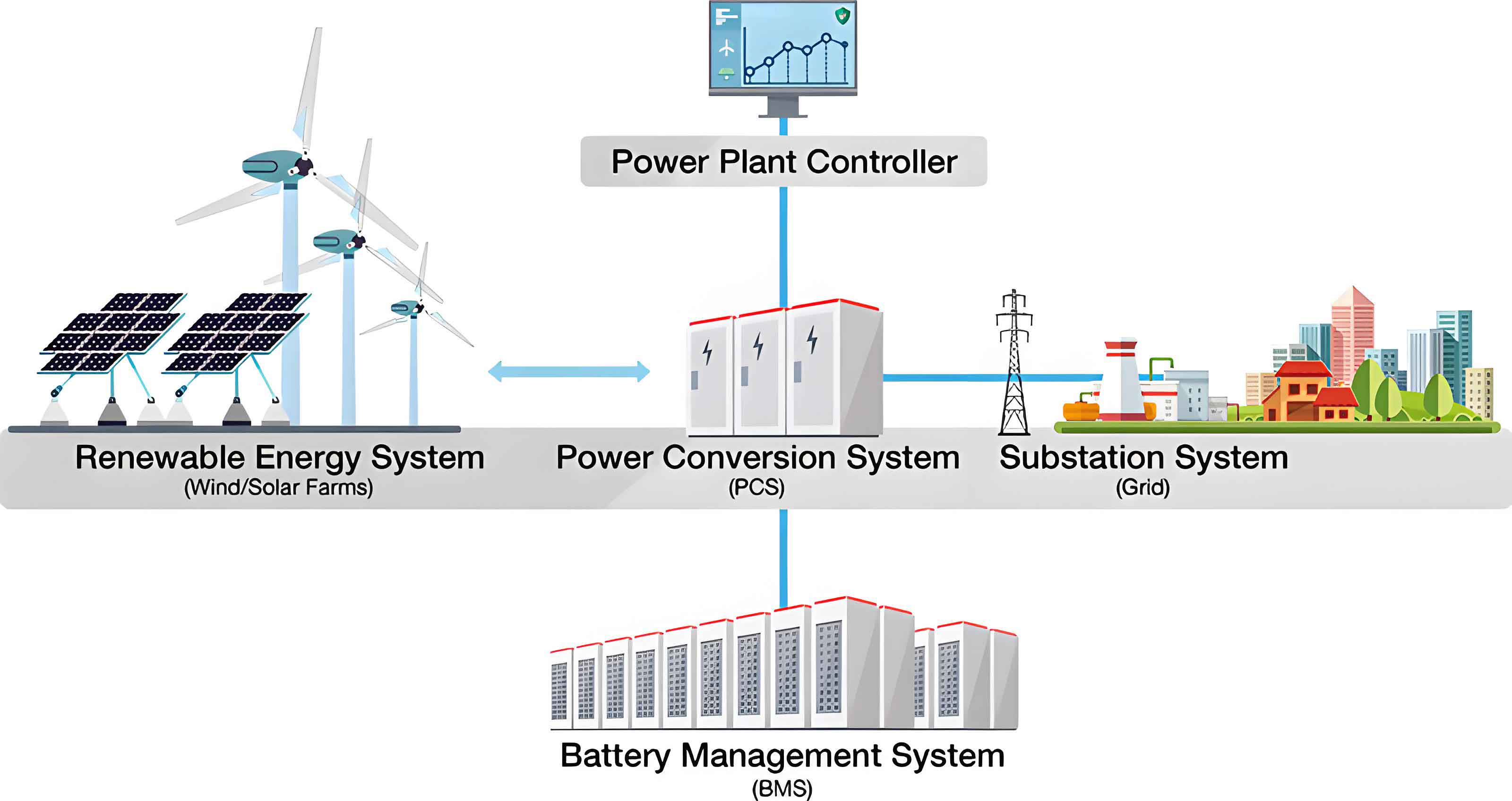
Topology of the Hybrid Energy Storage System
The direct-mounted hybrid energy storage system is connected in parallel to the DC side between the WFMMC and its DC circuit breaker. The system consists of two parallel branches: a supercapacitor energy storage system and a lithium battery energy storage system. Each branch is constructed from a series connection of sub-modules, with each sub-module containing a half-bridge circuit, a DC capacitor, a bidirectional DC/DC converter (for supercapacitor) or a pre-charge unit (for battery), and the energy storage module itself. The key parameters of the system are summarized in Table 1 and Table 2.
| Parameter | Symbol | Value |
|---|---|---|
| Number of active sub-modules | \(N_{\text{sc}}\) | 50 |
| Number of redundant sub-modules | \(M_{\text{sc}}\) | 8 |
| Rated DC capacitor voltage of sub-module | \(U_{\text{C,scN}}\) | 8 kV |
| Sub-module DC capacitor | \(C_{\text{sc}}\) | 0.01 F |
| Supercapacitor module equivalent capacitance | \(C_{\text{S}}\) | 0.3 F |
| Filter inductance | \(L\) | 3.125 mH |
| Inductor resistance | \(R_{\text{L}}\) | 0.05 \(\Omega\) |
| Maximum supercapacitor voltage | \(U_{\text{CS,max}}\) | 4 kV |
| Initial supercapacitor voltage | \(U_{\text{CS0}}\) | 2 kV |
| Switching frequency of DC/DC converter | \(f_{\text{s}}\) | 2 kHz |
| SOC lower limit (safe) | \(\text{SOC}_{\text{C,min}}\) | 20% |
| SOC low threshold | \(\text{SOC}_{\text{C,low}}\) | 30% |
| SOC high threshold | \(\text{SOC}_{\text{C,high}}\) | 70% |
| SOC upper limit (safe) | \(\text{SOC}_{\text{C,max}}\) | 80% |
| Parameter | Symbol | Value |
|---|---|---|
| Number of active sub-modules | \(N_{\text{bat}}\) | 40 |
| Number of redundant sub-modules | \(M_{\text{bat}}\) | 3 |
| Rated DC capacitor voltage of sub-module | \(U_{\text{C,batN}}\) | 10 kV |
| Sub-module DC capacitor | \(C_{\text{bat}}\) | 8000 \(\mu\)F |
| Pre-charge resistor | \(R\) | 0.06 \(\Omega\) |
| Battery cells in series per module | \(N_{\text{bats}}\) | 1000 |
| Battery cells in parallel per module | \(N_{\text{batp}}\) | 100 |
| Maximum voltage of single cell | \(U_{\text{bat1,max}}\) | 20 V |
| Minimum voltage of single cell | \(U_{\text{bat1,min}}\) | 10 V |
Improved Virtual Impedance Control for Hybrid Energy Storage System
Conventional virtual impedance control applies a virtual capacitor \(C_{\text{x}}\) to the supercapacitor branch and a virtual resistor \(R_{\text{x}}\) to the battery branch, resulting in frequency-dependent power sharing. The transfer functions from the total DC current \(I_{\text{F}}\) to the supercapacitor current \(i_{\text{sc}}\) and battery current \(i_{\text{bat}}\) are given by:
$$G_{\text{sc}}(s) = \frac{i_{\text{sc}}}{I_{\text{F}}} = \frac{sR_{\text{x}}C_{\text{x}}}{1 + sR_{\text{x}}C_{\text{x}}}$$
$$G_{\text{bat}}(s) = \frac{i_{\text{bat}}}{I_{\text{F}}} = \frac{1}{1 + sR_{\text{x}}C_{\text{x}}}$$
The cutoff frequency is \(\omega_{\text{c}} = 1/(R_{\text{x}}C_{\text{x}})\). A higher \(R_{\text{x}}\) reduces the cutoff frequency, assigning more high-frequency power to the supercapacitor. However, a fixed \(R_{\text{x}}\) may lead to supercapacitor SOC violation if the fault is severe. To overcome this, I propose an improved virtual impedance control that dynamically adjusts \(R_{\text{x}}\) based on the supercapacitor SOC, denoted as \(\text{SOC}_{\text{C}}\). The relationship is illustrated in Figure 5 of the original paper (not reproduced here). For charging mode (absorbing surplus power), when \(\text{SOC}_{\text{C}}\) is below a high threshold \(\text{SOC}_{\text{C,high}}\), the virtual resistance remains at its initial value \(R_{\text{x0}}\) to allow fast response. When \(\text{SOC}_{\text{C}}\) enters the range \([\text{SOC}_{\text{C,high}}, \text{SOC}_{\text{C,max}}]\), \(R_{\text{x}}\) decreases linearly:
$$R_{\text{x}} = R_{\text{x0}} \frac{\text{SOC}_{\text{C,max}} – \text{SOC}_{\text{C}}}{\text{SOC}_{\text{C,max}} – \text{SOC}_{\text{C,high}}}$$
This reduces the cutoff frequency, shifting power to the battery and slowing the supercapacitor SOC rise. At \(\text{SOC}_{\text{C,max}}\), \(R_{\text{x}} = 0\), so all current flows to the battery. This adaptive mechanism keeps the supercapacitor SOC within safe limits.
The double-closed-loop control for a single supercapacitor sub-module is shown in the original paper (Figure 6). The inner current loop regulates the inductor current \(i_{\text{L}}\), while the outer voltage loop maintains the DC capacitor voltage \(U_{\text{C,sc}}\). The transfer functions of the DC/DC converter are:
$$G_{\text{id}}(s) = \frac{\Delta i_{\text{L}}(s)}{\Delta D(s)} = \frac{U_{\text{C,sc0}}}{LCs^2 + R_{\text{L}}Cs + 1}$$
$$G_{\text{ui}}(s) = \frac{\Delta U_{\text{C,sc}}(s)}{\Delta i_{\text{L}}(s)} = \frac{LCs^2 + R_{\text{L}}Cs + 1}{C_{\text{sc}}D_0^2s}$$
where \(U_{\text{C,sc0}}\) is the steady-state DC capacitor voltage, \(D_0\) is the steady-state duty cycle, and \(C = C_{\text{S}} + C_{\text{sc}}\) is the equivalent capacitance.
For the battery energy storage system, a simple PI controller adjusts the number of inserted sub-modules \(N_{\text{bat,ref}}\) to regulate the DC voltage reference, as illustrated in Figure 7 of the original paper. The sorting algorithm ensures equal energy distribution among sub-modules.
DC Overvoltage Suppression by Adaptively Reducing Inserted MMC Sub-modules
The sub-module capacitors of both WFMMC and GSMMC have a voltage rating of 20 kV, and can withstand 1.1 p.u. (22 kV) for a short duration according to industry standards. Before activating the hybrid energy storage system, we first allow the sub-module capacitors to absorb surplus energy by reducing the number of inserted sub-modules. The DC voltage of the MMC is related to the average sub-module capacitor voltage \(U_{\text{C}}(t)\) and the number of inserted sub-modules per arm \(N(t)\):
$$U_{\text{dc}}(t) = N(t)U_{\text{C}}(t)$$
During steady state, \(N(t) = N_0 = 20\) and \(U_{\text{dcN}} = N_0U_{\text{CN}} = 400\) kV. The surplus power \(\Delta P\) charges the equivalent capacitance of the two MMCs. The energy conservation equation is:
$$\Delta P \cdot (t – t_0) = \frac{1}{2}C_{\text{eq}}(t)U_{\text{dc}}^2(t) – \frac{1}{2}C_{\text{eqN}}U_{\text{dcN}}^2$$
where \(C_{\text{eq}}(t) = 12N_0C_0 N(t)/N(t) = 12N_0C_0\)? Actually, the equivalent capacitance per phase is \(6C_0\) for each MMC, and total for two MMCs is \(12C_0\) when all sub-modules are inserted. But when we reduce the number of inserted sub-modules, the per-phase equivalent capacitance increases because the same total sub-module capacitance is distributed over fewer inserted sub-modules. Specifically, if each arm has \(N_0\) total sub-modules but only \(N(t)\) are inserted, the effective arm capacitance becomes \(N_0C_0/N(t)\). For six arms (three phases, upper and lower), the total equivalent capacitance is \(6 \cdot (N_0C_0/N(t)) \cdot 2\)? Let me derive properly: Each arm has \(N_0\) sub-modules of capacitance \(C_0\). When \(N(t)\) are inserted, the arm capacitance is \(C_{\text{arm}} = C_0 N(t)\)? No: the capacitance of a string of \(N(t\) inserted (with others bypassed) is \(C_0/N(t)\)? Actually, in an MMC, the individual sub-module capacitors are connected in series in the current path. If \(N(t)\) sub-modules are inserted in series, the equivalent capacitance of that arm is \(C_0/N(t)\). But there are two arms per phase (upper and lower) that are in parallel for DC voltage, so per phase equivalent DC-side capacitance is \(2 \times (C_0/N(t))\). For three phases, total is \(6C_0/N(t)\). Therefore, the total equivalent capacitance of both MMCs is \(12C_0/N(t)\). In steady state, \(N(t)=N_0\), so \(C_{\text{eqN}} = 12C_0/N_0\). During fault, if we reduce \(N(t)\), \(C_{\text{eq}}(t) = 12C_0/N(t)\) increases. This allows the same energy surplus to be absorbed with a smaller voltage rise.
We introduce an adaptive coefficient \(K\) such that the DC voltage reference is reduced when \(U_{\text{dc}} > U_{\text{dcref}}\). The new reference is:
$$U_{\text{dcref}}(t) = U_{\text{dcref}} – K(U_{\text{dc}}(t) – U_{\text{dcref}})$$
where \(K\) is adjusted to maintain \(U_{\text{dc}}(t)\) near 1.05 p.u. (420 kV). The corresponding number of inserted sub-modules becomes:
$$N(t) = \frac{U_{\text{dcref}}(t)}{U_{\text{CN}}}$$
Combining these equations, we can derive the relationship for \(K\). The strategy is implemented as shown in Figure 8 of the original paper. When the DC voltage deviation exceeds 0.01 p.u., the adaptive algorithm switches to channel A; otherwise, it reverts to channel B with nominal \(N_0\).
Coordinated Fault Ride-through Strategy
The overall coordinated strategy proceeds as follows:
- Detect an AC fault at the receiving end.
- If the DC voltage deviation exceeds 0.01 p.u., reduce the number of inserted sub-modules in both WFMMC and GSMMC adaptively, allowing sub-module capacitors to absorb surplus energy.
- If the sub-module capacitor voltage exceeds 1.1 p.u. (22 kV), activate the hybrid energy storage system. The improved virtual impedance control governs the power sharing between supercapacitors and batteries, with virtual resistance dynamically adjusted based on supercapacitor SOC.
- When the DC voltage deviation falls below 0.01 p.u., restore the nominal number of inserted sub-modules and continue operating the hybrid energy storage system until the DC voltage returns to the rated value, then deactivate the HESS.
The coordination effectively reduces the required capacity of the energy storage system. For the studied system (80×5 MW wind farm, 0.2 s fault, three-phase short circuit), the surplus energy is 80 MJ. The MMC sub-module capacitors can absorb up to 12.6 MJ (from equation (8)), leaving 67.4 MJ for the HESS. This corresponds to a reduction in HESS capacity by about 15.75%.
Simulation Results and Discussion
I conducted simulations in PSCAD/EMTDC for the system shown in Figure 1 of the original paper. Three strategies were compared:
- Strategy 1: Proposed coordinated strategy (improved virtual impedance + MMC sub-module capacitor utilization).
- Strategy 2: Traditional fixed virtual impedance + MMC sub-module capacitor utilization.
- Strategy 3: Traditional fixed virtual impedance only (no MMC capacitor utilization).
The results for a three-phase short circuit at the receiving end (fault at 3.6 s, duration 0.2 s) are summarized in Table 3 and Table 4.
| Metric | Strategy 1 | Strategy 2 | Strategy 3 |
|---|---|---|---|
| Maximum DC voltage (kV) | 419 | 419 | 425 |
| Final supercapacitor SOC (%) | 74 | 82 | 95 |
| MMC sub-module capacitor max voltage (kV) | 22 (1.1 p.u.) | 22 | Not utilized (immediately HESS) |
| Maximum supercapacitor power (MW) | ~200 (peak) | ~200 | ~200 (but for longer duration) |
| Metric | Strategy 1 | Strategy 2 | Strategy 3 |
|---|---|---|---|
| Maximum DC voltage (kV) | 407 | 407 | 410 |
| Final supercapacitor SOC (%) | 55.1 | 55.1 | 64 |
| MMC sub-module capacitor max voltage (kV) | 22 | 22 | Not utilized |
During the three-phase fault, strategies 1 and 2 both utilize MMC capacitors first, delaying HESS activation. However, strategy 1’s adaptive virtual resistance reduces the supercapacitor share after SOC reaches 70% (at about 3.82 s), causing the battery to absorb more power. As a result, the final SOC in strategy 1 is 74%, well below the 80% limit, whereas strategy 2 reaches 82%, exceeding the recommended safe limit. Strategy 3 (no MMC utilization) results in a SOC of 95%, dangerously close to overcharge. The DC voltage in strategies 1 and 2 is slightly lower (419 kV) than strategy 3 (425 kV) because of the additional capacitive energy storage. For the single-phase fault, the surplus is smaller; thus the SOC never reaches 70% in strategies 1 and 2, so the virtual resistance does not change, and both strategies perform identically. Nevertheless, the coordinated approach still reduces the HESS energy absorption compared to strategy 3, keeping the final SOC at 55.1% versus 64%.
Conclusion
I have presented a coordinated fault ride-through strategy for offshore wind power MMC-HVDC systems that leverages both a hybrid energy storage system (supercapacitor and lithium battery) and the energy margin of MMC sub-module capacitors. The main contributions are:
- An improved virtual impedance control for the hybrid energy storage system that adjusts the virtual resistance based on the supercapacitor SOC, preventing overcharge and maintaining safe operation.
- An adaptive reduction of inserted MMC sub-modules to absorb surplus energy using the inherent capacitor energy margin, thereby reducing the required capacity of the hybrid energy storage system.
- A coordinated activation scheme that first uses MMC capacitors and only activates the energy storage system when necessary, minimizing cost and improving system resilience.
Simulation results confirm that the proposed strategy effectively limits DC overvoltage to below 1.1 p.u. during faults, keeps the supercapacitor SOC within safe bounds (e.g., 74% instead of 95% for a severe three-phase fault), and reduces the energy storage system capacity by approximately 15.75% compared to using the energy storage system alone. The method is applicable to both three-phase and single-phase faults and enhances the overall fault ride-through capability of offshore wind integration.