
1. introduction
Recently, the world power system has begun to decentralize and decarbonize. The excessive use of fossil fuels for power generation not only leads to an increase in fuel costs and consumption of fossil fuels, but also causes environmental problems such as global warming. This has led to the exploration of alternative solutions, such as solar photovoltaic (SPV), wind energy, and other types of renewable energy resources (RES) for power generation. The rapid progress of integrating RES into this practical function has redesigned the structure of centralized utilities and proposed the Distributed Energy System (DES), which is a key component of Distributed Energy Resources (DERs). Energy is unpredictable, and their power generation is uncontrollable. The rapid rise of electric driven power generation has brought new challenges to the controllable and safe operation of the power grid. In the late 1990s, the United States and Europe began exploring decentralized solutions to manage the integration of thousands of DERs in a way that maximizes reliability and resilience in the face of natural disasters, physical and network attacks, and cascading power failures. They have obtained a grid structured solution for local management of power generation and demand in grid partitions that can be automatically isolated in the event of a main grid failure, known as a “microgrid”.
The microgrid is composed of a large number of RES, and the load and energy storage system are connected together in a good way, thereby reducing the physical distance between the load and the power source. In the future power system, microgrids will become an important component of the effective integration of renewable energy, energy storage systems, and loads. A detailed review was conducted on microgrids and different energy management systems. Due to the reduction of power conversion stages, DC microgrids are more flexible than AC microgrids. In addition, DC microgrids are not affected by common power quality issues such as frequency synchronization, reactive power flow, and harmonic current in AC systems. Therefore, compared to AC microgrids, the overall control of DC microgrids is less complex. Due to the limited modeling capabilities of DC microgrids, they have been widely used in fields such as building power systems, data centers, residential communities, and plug-in hybrid vehicles.
2. Related work
The rapid development of renewable energy generation has brought many challenges to the safe, reliable, and controllable operation of microgrids. The main research direction in the field of microgrids is energy management and control of microgrids. A centralized energy management system with power tracking control was studied. Athira et al. proposed a prototype model of an isolated DC microgrid with hybrid energy storage system (HESS). In the energy management of microgrids composed of advanced photovoltaic power generation units, Al Dhaifallah et al. proposed a micro gas turbine. Han et al. proposed a power optimization method for microgrids based on hierarchical control.
This article introduces the design and simulation of an independent DC microgrid suitable for residential distribution systems. A simple structure of a DC microgrid with energy storage system and power conversion unit was discussed in detail. The microgrid model was simulated in MATLAB and the performance of various components of the microgrid was analyzed.
3. Design of Independent DC Microgrid
Figure 1 shows an independent DC microgrid with SPV source, unidirectional and bidirectional DC-DC converters, energy storage system (ESS), and DC load. The SPV system adopts a maximum power point tracking (MPPT) controller to obtain the maximum power output from the SPV source.
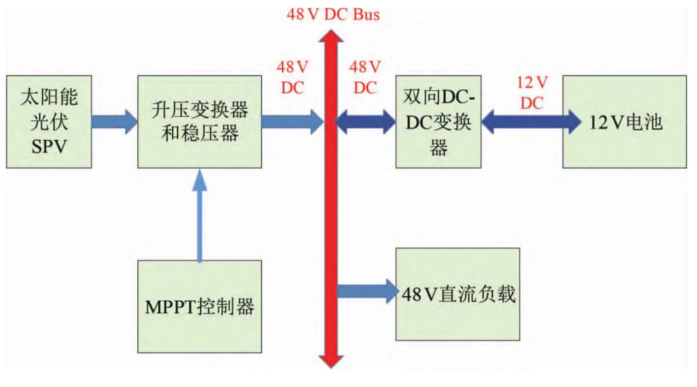
MPPT controls the DC-DC converter connected to the photovoltaic power supply. The bidirectional DC-DC converter connects the energy storage system and the DC bus. The system uses a 12V battery as the energy storage system. The 12V required for battery charging is provided by a bidirectional DC-DC converter. This 12V DC is converted back to 48V DC again, providing power for the DC bus and the 48V DC load connected to the DC bus.
3.1 Mathematical Model of SPV Battery
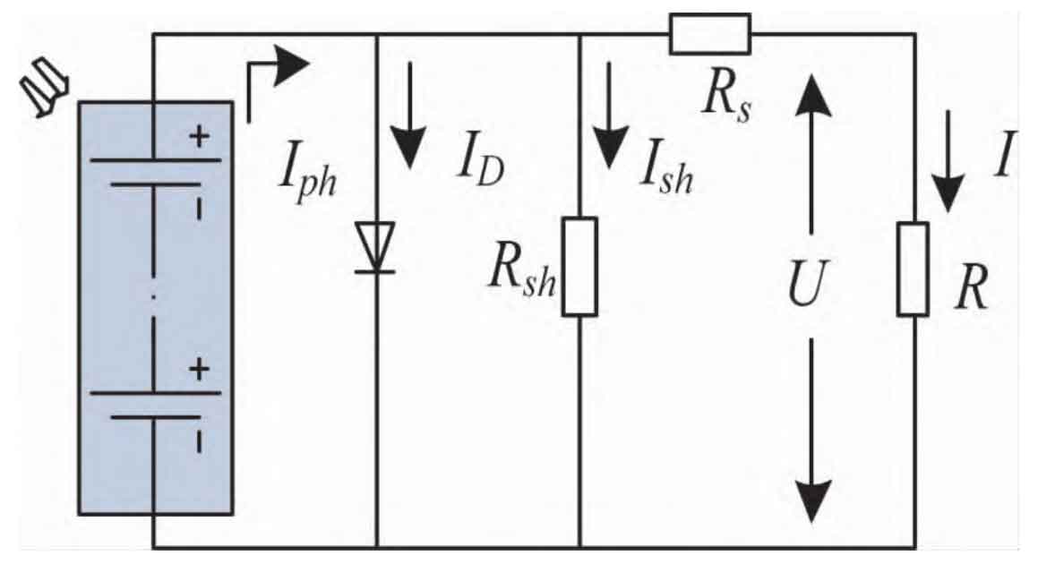
Figure 2 shows the equivalent circuit of an SPV battery. It consists of a current source (Iph), a diode (D), a series resistor Rse, and a parallel resistor Rp. The output current of an ideal SPV battery can be expressed as:
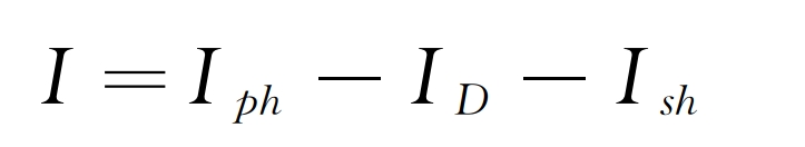
Among them, Iph is the output current generated by the SPV battery, and Id is the Shockley equation.
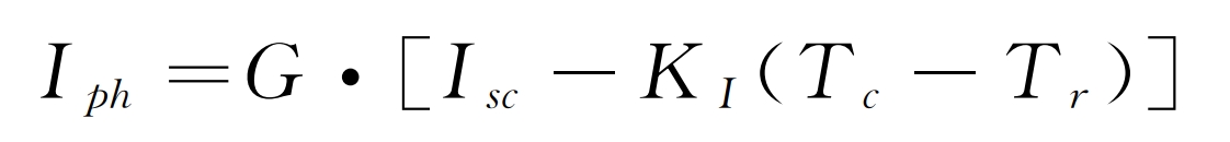
Among them, Isc is the short-circuit current of the SPV battery. The short-circuit temperature coefficient is represented by KI, the reference temperature of SPV batteries is represented by Tr, and the Standard Test Conditions (STC) of SPV batteries are the battery temperature, Tc=25 ℃, and solar irradiation G=1000W/m ^ 2.
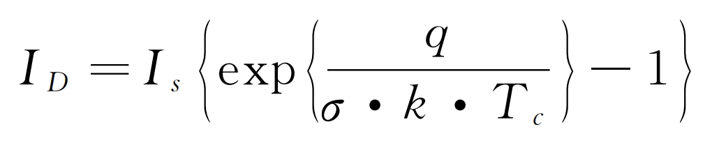
Among them, Is is the diode saturation current, and q is the electronic charge (1.60 × 10⁻¹⁹ ℃), k is the Boltzmann constant (1.38 × 10⁻²³J/K). σ It is an ideal factor.
3.2 SPV characteristics
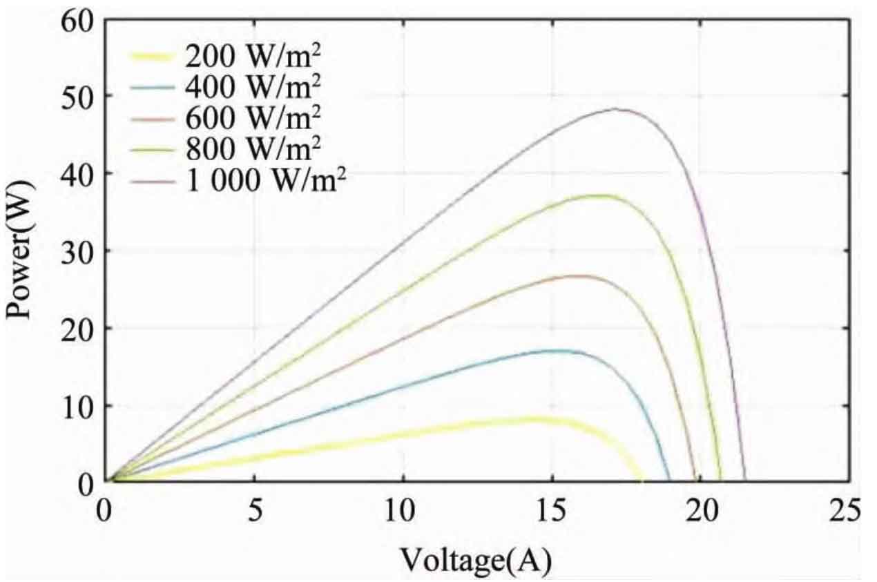
The output of SPV is intermittent and random, meaning that the power output of the SPV module/array varies with the temperature or irradiance of the incident light on the SPV battery. Therefore, the characteristics of SPV batteries are nonlinear. The power voltage characteristics of SPV batteries under different irradiances and temperatures are shown in Figure 3.
3.3 MPPT
When irradiation increases, the SPV current increases, and vice versa. But the voltage levels under different irradiation conditions are almost the same. Similarly, the SPV voltage decreases with increasing temperature, while the current remains almost unchanged. The results indicate that power varies with temperature and irradiation, and the maximum power point (MPP) of SPV increases with increasing irradiation, while decreases with increasing temperature. Therefore, in order to obtain maximum power, it is necessary to change the working point of the power regulation unit to match the load resistance of the PV source. The MPPT controller coordinates with the SPV system to operate the system under MPP conditions. The photovoltaic energy conversion system uses MPPT to continuously adjust the operating point of the DC-DC converter to extract maximum power from the solar array, regardless of weather conditions. The most commonly used maximum power tracking algorithm is the perturbation and observation (P&O) algorithm. There are several other algorithms, such as incremental conductance algorithm, constant voltage algorithm, and short-circuit current algorithm. Many literature has also proposed and discussed soft computing and hybrid MPPT. In the traditional MPPT algorithm, the P&O algorithm is mainly applied to SPV systems. This technology is based on the climbing principle, which means that the working point of the photovoltaic module moves in the direction of increasing power. Although P&O algorithm has its advantages, it also has certain drawbacks. The main drawback of P&O is that it causes oscillations in the duty cycle, forcing the working point to move back and forth around the MPP. There is also a simple offline method for MPP tracking, called look up table (LUT) MPPT, which uses previously stored computational data in memory for MPP tracking. This article uses LUTMPPT controller to track MPP. Compared to other traditional MPPTs, LUTMPPT has greater advantages because of its shorter calculation time. Fast output response speed and stable output. LUT was developed using previously calculated data. LUT has two input ranges, 500-1300W/m2 with an interval of 100W/m2, and a temperature range of 25-55 ℃ with an interval of 10 ℃. Irradiance and temperature are the inputs of LUT, and the duty cycle is directly used as the output.
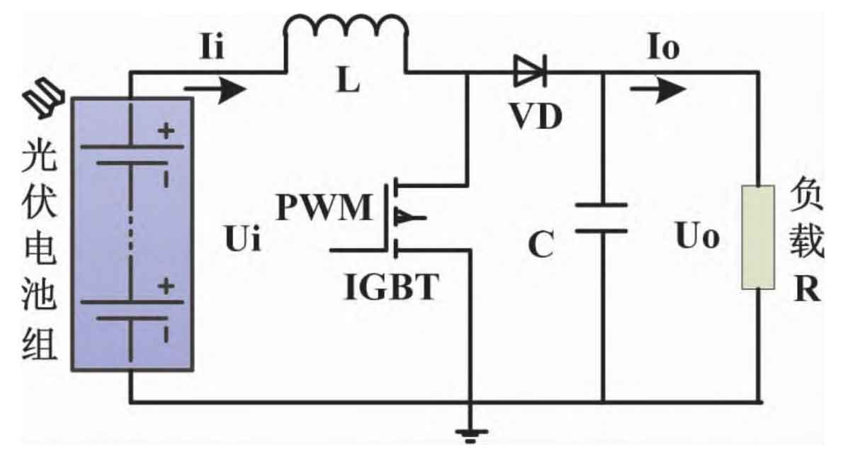
3.4 DC-DC converter
The energy collection of the SPV system requires an efficient DC-DC converter, which mainly uses a DC-DC boost converter. Figure 4 shows the circuit of the DC-DC boost converter. The bidirectional DC-DC converter switches from the power supply to the energy storage system and discharges the battery to provide energy to the load. A dual switch bidirectional DC converter (48-12V) was designed and connected to the 48V DC bus. The battery is charged in buck mode and discharged in boost mode.
4. Results and Discussion
The rated output power of the selected SPV module is 100W. The DC-DC converter has 18V input and 36V output. The output of the boost converter is regulated by a 48V regulator, providing a constant 48V for the DC bus. Design a DC-DC converter using standard design equations. The specifications of the SPV panel and the design parameters of the boost and bidirectional DC converters are shown in Table 1 and simulated in the MATLAB 2016a version software.
| Parameters | Value |
| Maximum power | 100 W |
| Open circuit voltage | 21.84V |
| Short circuit current | 6.11A |
| Maximum power point voltage | 17.99V |
| Maximum power point current | 5.57A |
| Output voltage | 48V |
| Inductance | 0.54mH |
| Capacitance | 76.9μF |
| Switching frequency | 10kHz |
Figure 5 shows the duty cycle tracking of the MPPT controller under given input conditions. Based on the input LUT, the duty cycle is extracted from pre allocated data, so the change in output relative to the input is instantaneous and the duty cycle is constant.
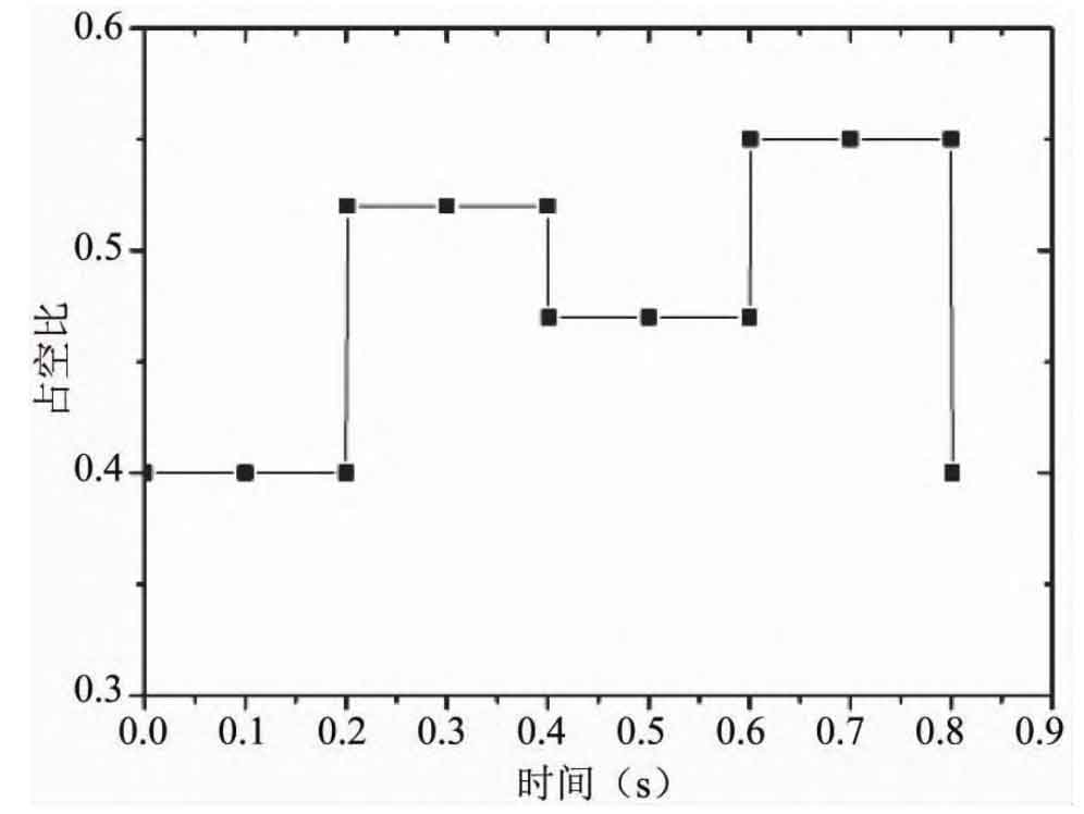
Figure 6 shows the output voltage of the SPV module, DC-DC converter, and boost regulator. The input DC voltage of the DC-DC converter increases and changes, resulting in a changing DC output. The designed DC bus voltage of the system is 48V. In order to obtain a constant output voltage of 48V on the DC bus side, a 48V boost voltage regulator is connected between the DC-DC boost converter and the DC bus. Figure 6 shows the regulated DC output generated by the regulator. The control of the regulator is achieved by a PI controller, providing a constant output voltage (48V) under all conditions. From the results, it can be seen that when the input voltage of the regulator changes, the PI controller adjusts the duty cycle, returns the output voltage to the reference value, and maintains a constant 48V output.
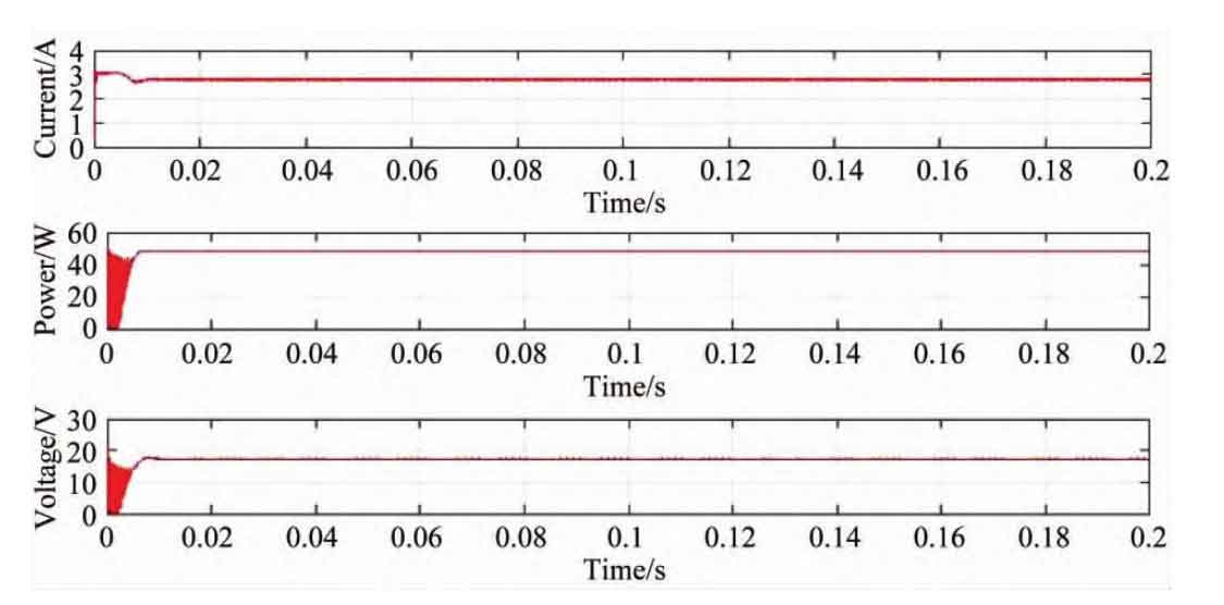
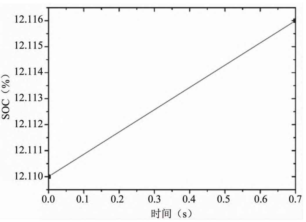
Energy storage system charges when operating in the buck mode of the bidirectional converter and discharges when operating in the boost mode. In order to study the charging and discharging characteristics of energy storage system, a 48V battery is connected as a load to the DC bus, and the bidirectional converter operates in a Buck mode. Figure 7 depicts the charging and discharging conditions of the energy storage system battery and the load battery. It can be seen that while the energy storage system is discharging, the DC bus load (48V battery) is charging.
5.Conclusion
This article introduces the design and simulation of a single machine DC microgrid system with energy storage system. The microgrid model established through simulation was used to analyze the operation and performance of components such as converters, regulators, MPPT controllers, energy storage system, and loads under different input conditions. The simulation results were presented and discussed in detail.