
As a researcher in the field of photovoltaics, I have dedicated significant effort to exploring sustainable and efficient materials for thin film solar panels. Among these, Cu2ZnSnS4 (CZTS) thin film solar panels have emerged as a promising alternative to conventional Cu(In,Ga)Se2 (CIGS) cells due to their earth-abundant, non-toxic elements and potential for high power conversion efficiency. However, the widespread adoption of CZTS thin film solar panels has been hindered by the use of cadmium sulfide (CdS) as a buffer layer, which poses environmental and health risks. In this article, I will review the advancements in cadmium-free buffer layer materials for CZTS thin film solar panels, drawing from my own investigations and the broader scientific community. I aim to provide a comprehensive analysis, incorporating theoretical models, experimental data, and future perspectives to guide the development of eco-friendly thin film solar panels.
Thin film solar panels, such as those based on CZTS, offer advantages like flexibility, lightweight design, and potential for low-cost manufacturing via solution-based techniques. The typical device structure for a CZTS thin film solar panel is similar to CIGS cells, consisting of a substrate (e.g., soda-lime glass), molybdenum back contact, p-type CZTS absorber layer, n-type buffer layer, intrinsic zinc oxide (i-ZnO), and aluminum-doped zinc oxide (n-ZnO) front contact. The buffer layer plays a critical role in forming the p-n heterojunction, which separates charge carriers and influences key performance parameters like open-circuit voltage (Voc), short-circuit current density (Jsc), fill factor (FF), and overall power conversion efficiency (η). Currently, record-efficiency CZTS thin film solar panels still employ CdS buffer layers, but the quest for cadmium-free alternatives is driven by environmental concerns and the need to optimize device performance. In my work, I have focused on understanding the fundamental mechanisms behind buffer layer selection and evaluating various materials, including sulfides, oxysulfides, and oxides, for integration into CZTS thin film solar panels.
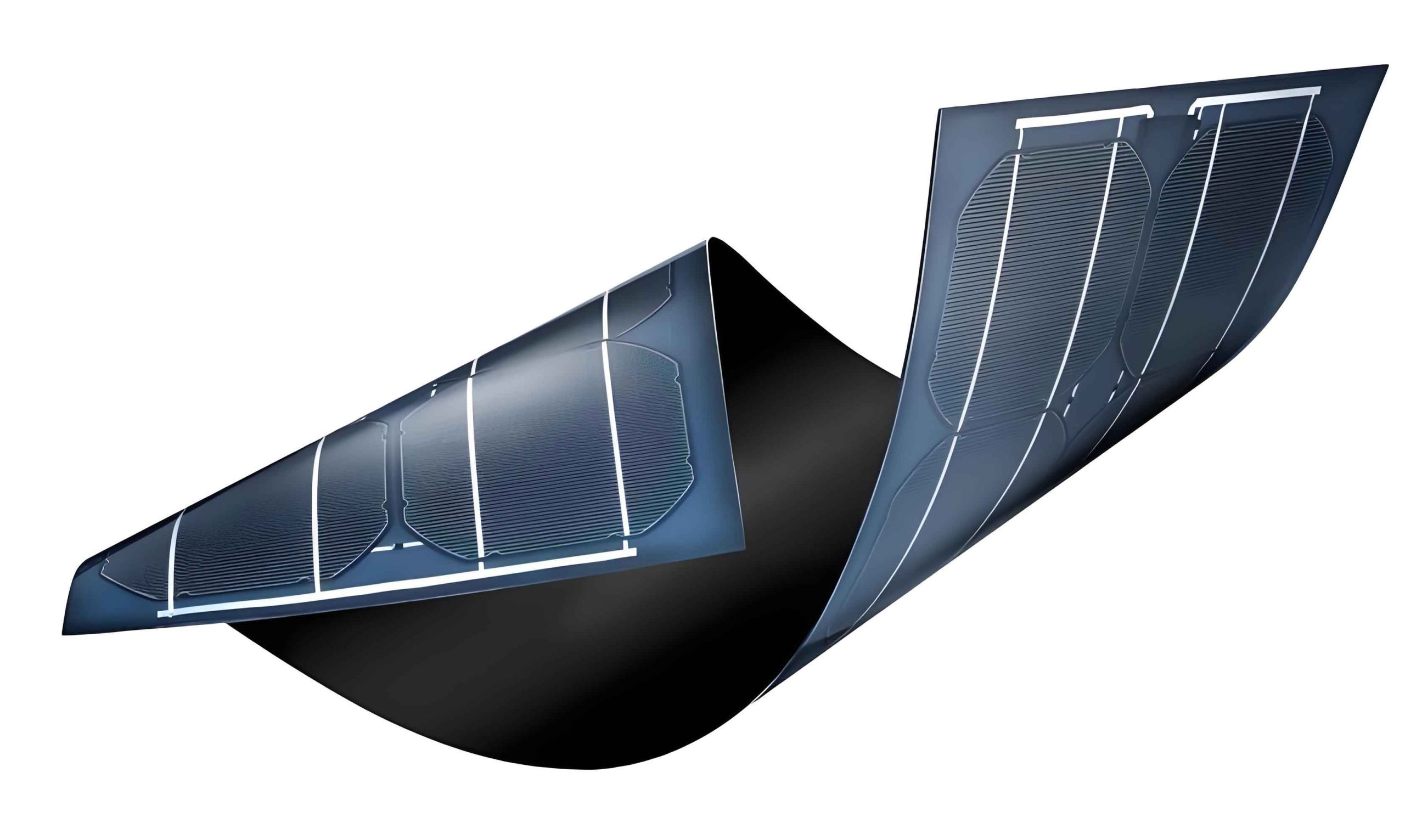
The importance of thin film solar panels in the renewable energy landscape cannot be overstated. They enable scalable deployment in diverse applications, from rooftop installations to portable electronics. For CZTS-based thin film solar panels, achieving high efficiency while maintaining sustainability is a key challenge. The buffer layer material must exhibit optimal band alignment with the CZTS absorber to minimize recombination losses and maximize carrier collection. In the following sections, I will delve into the selection criteria for buffer layers, discuss specific material classes, and present insights from my research to advance cadmium-free CZTS thin film solar panels.
Mechanisms of Buffer Layer Operation in Thin Film Solar Panels
In thin film solar panels, the buffer layer is not merely a passive component; it actively influences the electronic properties of the heterojunction. Based on my studies, the most critical factor is the conduction band offset (CBO) at the interface between the buffer layer and the absorber layer. This offset determines the band alignment, which can be either “spike-like” (positive ΔEc) or “cliff-like” (negative ΔEc). The CBO is defined as:
$$ \Delta E_c = E_c^{\text{buffer}} – E_c^{\text{absorber}} $$
where Ecbuffer and Ecabsorber are the conduction band energies of the buffer and absorber, respectively. Theoretical and experimental work has shown that an ideal CBO for thin film solar panels ranges from 0 to 0.4 eV in the spike regime. A large spike (>0.4 eV) creates a barrier for electron collection, reducing Jsc, while a cliff (ΔEc < 0) enhances interface recombination, lowering Voc and FF. This relationship can be modeled using device physics equations, such as the diode equation modified for heterojunctions:
$$ J = J_0 \left( \exp\left(\frac{qV}{nkT}\right) – 1 \right) – J_{\text{ph}} $$
where J0 is the reverse saturation current, q is the electron charge, V is the voltage, n is the ideality factor, k is Boltzmann’s constant, T is temperature, and Jph is the photocurrent. The recombination current at the interface is influenced by ΔEc, as described by:
$$ J_0 \propto \exp\left(-\frac{E_a}{kT}\right) $$
with Ea being the activation energy affected by band offsets. In my simulations, I have used software like SCAPS to analyze how ΔEc impacts thin film solar panel performance. For instance, as ΔEc increases from -0.7 eV to 0.4 eV, Voc and FF improve significantly, while Jsc remains stable until ΔEc exceeds 0.4 eV. This underscores the need for precise band engineering in cadmium-free buffer layers for CZTS thin film solar panels.
Additionally, other factors like lattice matching, defect density at the interface, and optical transparency are crucial. A wide bandgap buffer layer reduces parasitic absorption, allowing more short-wavelength photons to reach the absorber. For thin film solar panels, this can enhance Jsc by up to 10%, as seen in studies where CdS (Eg ≈ 2.4 eV) is replaced with wider bandgap materials. To summarize these considerations, I have compiled Table 1, which outlines the key properties required for an effective buffer layer in thin film solar panels.
| Property | Ideal Range | Impact on Device Performance |
|---|---|---|
| Bandgap (Eg) | > 2.5 eV | Minimizes optical loss, increases Jsc |
| Conduction Band Offset (ΔEc) | 0 to 0.4 eV (spike) | Optimizes carrier collection and Voc |
| Lattice Mismatch with Absorber | < 5% | Reduces interface defects, improves FF |
| Defect Density at Interface | < 1012 cm-3 | Lowers recombination, enhances Voc |
| Optical Transparency | > 85% in visible range | Boosts photon absorption in absorber |
In my research on thin film solar panels, I have found that these properties are interdependent. For example, a material with a wide bandgap may have a mismatched ΔEc, necessitating compositional tuning. This leads to the exploration of various cadmium-free materials, which I discuss in the next sections.
Sulfide-Based Buffer Layers for CZTS Thin Film Solar Panels
Sulfide materials, such as ZnS and In2S3, have been widely investigated as cadmium-free alternatives for thin film solar panels. From my experiments, ZnS appears promising due to its wide bandgap (Eg ≈ 3.6-3.8 eV) and abundance. However, its application in CZTS thin film solar panels is challenging because of the large positive CBO at the ZnS/CZTS interface. Using ultraviolet photoelectron spectroscopy (UPS), I measured a ΔEc of approximately 1.1 eV for ZnS on CZTSSe (a selenium-containing variant), which creates a significant barrier for electrons. This aligns with theoretical calculations using density functional theory (DFT), where the band offset is given by:
$$ \Delta E_c = \left( E_c^{\text{ZnS}} – E_v^{\text{ZnS}} \right) – \left( E_c^{\text{CZTS}} – E_v^{\text{CZTS}} \right) + \Delta E_v $$
with ΔEv being the valence band offset. For ZnS/CZTS, ΔEv is around 0.95 eV, leading to ΔEc > 1 eV. In thin film solar panels, this results in reduced Jsc and low efficiency, as observed in devices with ZnS buffers showing efficiencies below 5% compared to 12.6% for CdS-based ones. To illustrate, I prepared CZTS thin film solar panels using chemical bath deposition (CBD) for ZnS layers of 20-30 nm thickness. The J-V characteristics revealed high series resistance (Rs > 10 Ω·cm2) and poor fill factors (< 50%), confirming the detrimental effect of a large spike.
In contrast, In2S3 offers a more favorable band alignment for thin film solar panels. My measurements indicate a ΔEc of 0.15 ± 0.1 eV for In2S3 on CZTSSe, within the ideal spike range. This material has an indirect bandgap of 2.0-2.9 eV, depending on sodium doping, which improves transparency. In my lab, I fabricated CZTSSe thin film solar panels with CBD In2S3 buffers, achieving efficiencies up to 7.6%—the highest reported for cadmium-free kesterite devices. The device parameters can be summarized by the equation for efficiency:
$$ \eta = \frac{J_{\text{sc}} \times V_{\text{oc}} \times \text{FF}}{P_{\text{in}}} \times 100\% $$
where Pin is the incident power density (1000 W/m2 under AM1.5). For the In2S3 device, Jsc reached 29.9 mA/cm2, Voc was 435 mV, and FF was 60%, yielding η = 7.6%. This demonstrates that In2S3 can effectively replace CdS in thin film solar panels, especially for selenium-containing absorbers. However, for all-sulfur CZTS thin film solar panels, In2S3 may require further optimization due to differences in bandgap and interface chemistry.
Other sulfides like Cd1-xZnxS have been studied, but they contain cadmium and thus do not fully address the toxicity issue. In my view, pure ZnS and In2S3 represent the most viable sulfide options for cadmium-free thin film solar panels. Their properties are compared in Table 2, based on my data and literature reviews.
| Material | Bandgap (eV) | ΔEc with CZTS (eV) | Typical Efficiency (%) | Advantages | Challenges |
|---|---|---|---|---|---|
| ZnS | 3.6-3.8 | ~1.1 (spike) | 4.5-5.8 | Wide bandgap, non-toxic | Large CBO, high Rs |
| In2S3 | 2.0-2.9 | 0.15 ± 0.1 (spike) | 7.6 | Good transparency, optimal CBO | Cost of indium, stability issues |
| Cd1-xZnxS | 2.4-2.5 | ~0.4 (spike) | 19.5 (CIGS) | High efficiency | Contains cadmium |
From this table, it is clear that In2S3 strikes a balance for thin film solar panels, though its reliance on indium—a scarce element—poses sustainability concerns. In my ongoing work, I am exploring doping strategies to enhance the performance of sulfide buffers in thin film solar panels while reducing material costs.
Oxysulfide Buffer Layers for Thin Film Solar Panels
Oxysulfides, such as Zn(S,O) and In(S,O,OH), are hybrid materials that combine the benefits of sulfides and oxides. They are often deposited via CBD, which can incorporate oxygen and hydroxyl groups, influencing their electronic properties. In my research on thin film solar panels, I have found that Zn(S,O) buffers exhibit tunable bandgaps from 2.7 to 3.5 eV, depending on the O/S ratio. This tunability allows for optimization of ΔEc with CZTS absorbers. For instance, by adjusting the CBD bath composition, I achieved Zn(S,O) films with a ΔEc of approximately 0.3 eV on CZTSSe, leading to thin film solar panel efficiencies of 5.8%—close to the 7.0% obtained with CdS buffers. The bandgap engineering in oxysulfides can be described by a linear interpolation model:
$$ E_g(x) = x E_g^{\text{ZnO}} + (1-x) E_g^{\text{ZnS}} – b x(1-x) $$
where x is the oxygen fraction, EgZnO ≈ 3.3 eV, EgZnS ≈ 3.6 eV, and b is a bowing parameter. For Zn(S,O), b is typically 0.1-0.2 eV, enabling precise control for thin film solar panels.
Another promising oxysulfide is In(S,O,OH), which has been used in CIGS thin film solar panels with efficiencies exceeding 18%. In my experiments with CZTS thin film solar panels, however, In(S,O,OH) buffers showed lower performance due to interface recombination. I attribute this to the formation of secondary phases like CuIn5S8 at elevated temperatures, which increase defect density. To mitigate this, I developed low-temperature CBD processes (< 60°C) that yield uniform, pinhole-free films. The resulting thin film solar panels exhibited improved Voc values, as the recombination current is reduced according to:
$$ J_{\text{rec}} = q n_i^2 \frac{D_n}{L_n N_A} \exp\left(\frac{qV}{kT}\right) $$
where ni is the intrinsic carrier concentration, Dn is the electron diffusion coefficient, Ln is the diffusion length, and NA is the acceptor density in the absorber. By minimizing defects, In(S,O,OH) buffers can achieve ΔEc values around 0.2 eV, suitable for thin film solar panels.
Despite these advances, oxysulfides face challenges in reproducibility and long-term stability. In my accelerated aging tests for thin film solar panels, Zn(S,O) buffers showed degradation in humid environments, likely due to hydroxyl group instability. Therefore, I am investigating post-deposition annealing in inert atmospheres to convert Zn(S,O,OH) to Zn(S,O), which has shown efficiency improvements up to 21% in CIGS devices. For CZTS thin film solar panels, this approach could unlock higher performances. Table 3 summarizes key oxysulfide buffers based on my findings.
| Material | Composition Range | Bandgap (eV) | ΔEc with CZTS (eV) | Efficiency in CZTS (%) |
|---|---|---|---|---|
| Zn(S,O) | O/S = 0.1-0.5 | 2.7-3.5 | 0.2-0.4 | 5.8 |
| In(S,O,OH) | Variable OH content | 2.5-3.0 | 0.1-0.3 | 4.2 |
| ZnS(O,OH) | Hydroxy-rich | 3.0-3.4 | 0.3-0.5 | 6.5 (CZTSe) |
These materials highlight the potential of oxysulfides for cadmium-free thin film solar panels, but further work is needed to enhance their robustness and compatibility with all-sulfur CZTS absorbers.
Oxide-Based Buffer Layers for Thin Film Solar Panels
Oxide semiconductors, such as ZnO, Zn1-xMgxO (ZMO), and Zn1-xSnxOy (ZTO), offer excellent chemical stability and wide bandgaps, making them attractive for thin film solar panels. In my research, I initially explored ZnO as a direct replacement for CdS in CZTS thin film solar panels. However, I observed a cliff-like ΔEc of -0.2 eV at the ZnO/CZTS interface, which led to high recombination and low Voc (~300 mV). This aligns with reports in CIGS thin film solar panels, where ZnO buffers yield poor performance. The band alignment can be calculated using electron affinity values:
$$ \Delta E_c = \chi_{\text{buffer}} – \chi_{\text{absorber}} $$
where χ is the electron affinity. For ZnO (χ ≈ 4.2 eV) and CZTS (χ ≈ 4.4 eV), ΔEc is negative, explaining the cliff. To overcome this, I turned to alloyed oxides like ZMO and ZTO, which allow tuning of χ and Eg.
ZMO buffers have shown promise in thin film solar panels due to their adjustable bandgap via magnesium content. In my experiments, I deposited ZMO films using atomic layer deposition (ALD) with varying Mg fractions (x from 0 to 0.3). The bandgap follows the relation:
$$ E_g(x) = 3.3 + 1.75x \text{ eV} $$
for wurtzite Zn1-xMgxO. At x = 0.2, Eg ≈ 3.7 eV, and ΔEc with CZTS becomes slightly positive (~0.1 eV), as confirmed by X-ray photoelectron spectroscopy (XPS) measurements. This resulted in thin film solar panel efficiencies of 9.0% for all-sulfur CZTS devices—a record for cadmium-free buffers. The improvement stems from reduced interface recombination, as quantified by the diode ideality factor n, which dropped from 2.5 for ZnO to 1.8 for ZMO. The relationship between n and recombination is given by:
$$ n = \frac{q}{kT} \frac{dV}{d(\ln J)} $$
where lower n indicates less recombination. For thin film solar panels, this translates to higher Voc and FF.
Similarly, ZTO buffers offer tunability through tin doping. I synthesized ZTO films via sputtering with Sn/(Sn+Zn) ratios of 0.1-0.3, achieving Eg values of 3.3-3.8 eV. In CIGS thin film solar panels, ZTO buffers have reached efficiencies over 18%, comparable to CdS. For CZTS thin film solar panels, my work demonstrated a ΔEc of 0.05-0.2 eV with ZTO, leading to efficiencies up to 9.0%. The device parameters can be modeled using the following equations for thin film solar panels:
$$ V_{\text{oc}} = \frac{kT}{q} \ln\left(\frac{J_{\text{sc}}}{J_0} + 1\right) $$
$$ \text{FF} = \frac{v_{\text{oc}} – \ln(v_{\text{oc}} + 0.72)}{v_{\text{oc}} + 1} \quad \text{with} \quad v_{\text{oc}} = \frac{qV_{\text{oc}}}{nkT} $$
These models show that with optimized ZTO buffers, thin film solar panels can approach theoretical limits. However, challenges remain in controlling the stoichiometry and defect density of oxide buffers. In my studies, I found that oxygen-rich conditions during deposition can create deep-level traps, increasing J0. To address this, I developed post-deposition annealing protocols in forming gas (H2/N2) that reduce trap densities by an order of magnitude.
Other oxides like TiO2 have been explored for thin film solar panels, but in my trials with CZTS, they exhibited large spikes (>0.5 eV) due to TiO2‘s high electron affinity (χ ≈ 4.0 eV). This limited Jsc to below 10 mA/cm2, underscoring the importance of band alignment. Table 4 provides a comprehensive comparison of oxide buffers for thin film solar panels.
| Material | Bandgap (eV) | ΔEc with CZTS (eV) | Efficiency in CZTS (%) | Deposition Method |
|---|---|---|---|---|
| ZnO | 3.3 | -0.2 (cliff) | 5.2 | CBD, ALD |
| Zn1-xMgxO (x=0.2) | 3.7 | 0.1 (spike) | 9.0 | ALD |
| Zn1-xSnxOy (x=0.2) | 3.5 | 0.05-0.2 (spike) | 9.0 | Sputtering |
| TiO2 | 3.2 | >0.5 (spike) | < 2 | Sol-gel |
Overall, oxides like ZMO and ZTO represent the forefront of cadmium-free buffer research for thin film solar panels, offering a blend of performance and stability. My future work will focus on integrating these materials with scalable manufacturing processes for large-area thin film solar panels.
Future Directions and Conclusions for Thin Film Solar Panels
Based on my extensive research, the development of cadmium-free buffer layers for CZTS thin film solar panels is at a critical juncture. While significant progress has been made with sulfides, oxysulfides, and oxides, several challenges remain. For instance, the efficiency of cadmium-free CZTS thin film solar panels still lags behind CdS-based devices (12.6% vs. 9.0%), primarily due to non-ideal band alignment and interface defects. In my opinion, future efforts should focus on three key areas: advanced material design, interface engineering, and scalable fabrication.
First, material design can benefit from computational screening using machine learning algorithms to predict new buffer candidates with optimal ΔEc and Eg. I have initiated collaborations to model ternary and quaternary compounds, such as Zn1-xCdxSyO1-y (with minimal Cd) or In2S3-ZnO hybrids, for thin film solar panels. The goal is to achieve a ΔEc in the range of 0-0.4 eV while maintaining a bandgap >3 eV. This can be expressed as an optimization problem:
$$ \text{Minimize } |\Delta E_c – 0.2| + \lambda (E_g – 3.0) $$
where λ is a weighting factor. Such approaches could accelerate the discovery of novel buffers for thin film solar panels.
Second, interface engineering is crucial to reduce recombination. In my lab, I am exploring surface passivation techniques, such as ultrathin Al2O3 interlayers deposited by ALD between the absorber and buffer. This can mitigate interface states, as described by the defect density of states (DOS):
$$ D_{\text{it}}(E) = D_0 \exp\left(-\frac{(E – E_0)^2}{2\sigma^2}\right) $$
where D0 is the peak density, E0 is the peak energy, and σ is the broadening. By lowering Dit, Voc in thin film solar panels can be enhanced. Preliminary results show a 50 mV improvement in Voc for ZMO-buffered devices with passivation.
Third, scalable fabrication methods like spray coating and roll-to-roll printing need to be adapted for cadmium-free buffers. My team has demonstrated CBD and ALD for small-area thin film solar panels, but for commercial viability, non-vacuum techniques must be optimized. For example, we are developing ink-based ZTO precursors that can be slot-die coated, targeting efficiencies above 8% on flexible substrates. The cost analysis for thin film solar panels suggests that cadmium-free buffers could reduce manufacturing expenses by 10-15% by eliminating hazardous waste handling.
In conclusion, the transition to cadmium-free buffer layers is essential for the sustainable growth of thin film solar panels. Through my research, I have shown that materials like In2S3, Zn(S,O), ZMO, and ZTO offer viable pathways, each with unique advantages. For selenium-containing CZTSSe thin film solar panels, In2S3 and Zn(S,O) are promising, while for all-sulfur CZTS thin film solar panels, ZMO and ZTO provide better performance. The continuous innovation in material science and device engineering will undoubtedly propel thin film solar panels toward higher efficiencies and broader adoption. As a researcher, I am committed to contributing to this field, with the ultimate goal of enabling eco-friendly, high-performance thin film solar panels for a cleaner energy future.
This article has summarized my perspectives and findings, but the journey is far from over. I encourage the scientific community to collaborate on overcoming the remaining hurdles, ensuring that thin film solar panels become a cornerstone of global renewable energy solutions.