
The global energy landscape is undergoing a profound transformation. As concerns over climate change, resource depletion, and environmental pollution intensify, the imperative to develop and deploy clean, renewable energy sources has never been greater. Among these, solar photovoltaic (PV) technology stands as a cornerstone of a sustainable energy future. While crystalline silicon has dominated the solar market for decades, accounting for over 80% of production, its limitations—particularly regarding manufacturing cost, energy intensity, and environmental footprint—have fueled the search for alternative solutions. This is where the compelling potential of **thin film solar panels** comes into sharp focus.
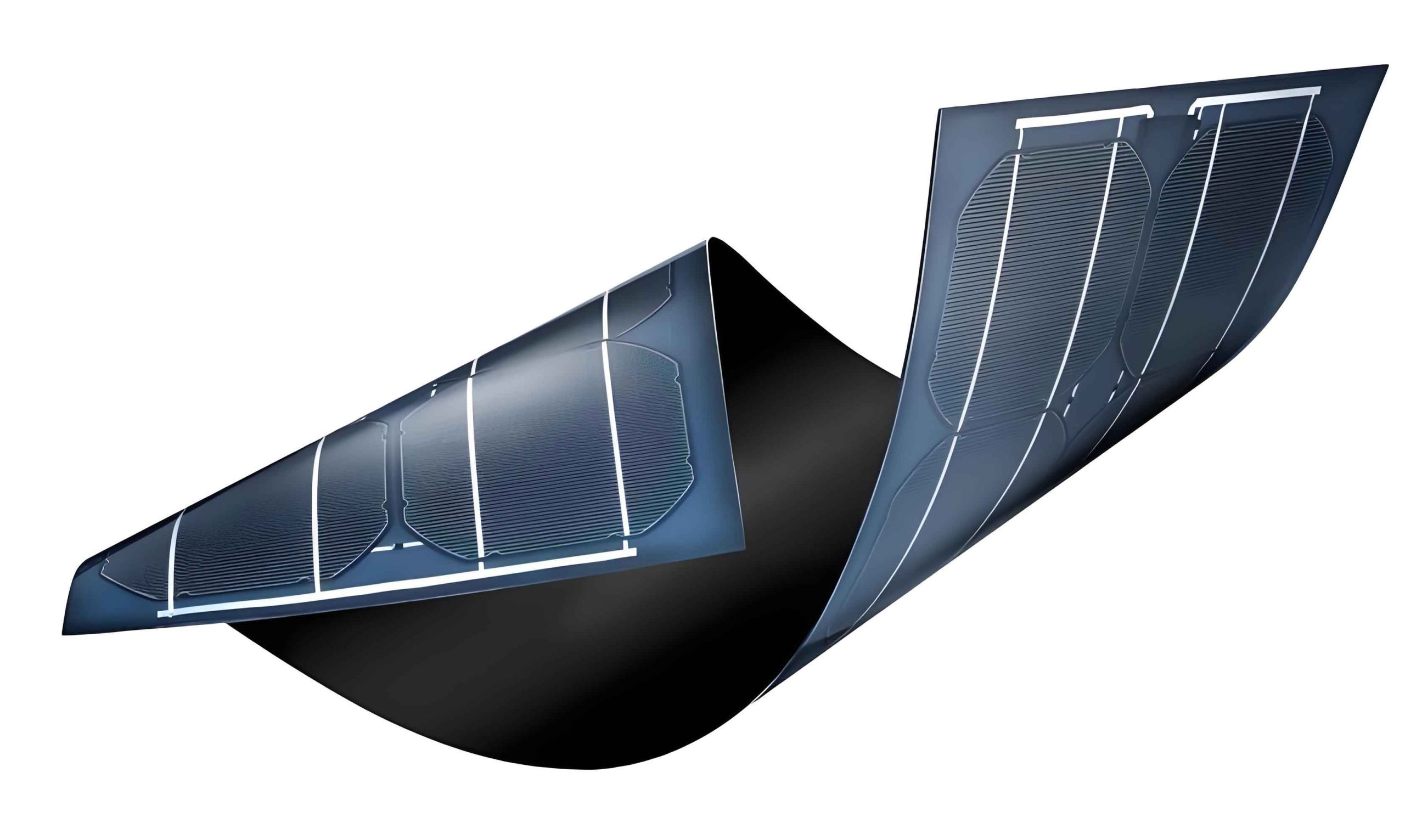
The paradigm of **thin film solar panels** represents a significant departure from conventional wafer-based silicon. Instead of slicing silicon ingots into wafers hundreds of micrometers thick, thin-film technologies involve depositing light-absorbing semiconductor materials in layers only a few micrometers thick onto low-cost substrates like glass, metal, or plastic. This approach offers intrinsic advantages: drastic reductions in material usage, lower energy payback times, suitability for flexible and building-integrated applications, and the potential for much lower manufacturing costs through high-throughput, continuous processes. Among the various thin-film contenders—including amorphous silicon (a-Si), copper indium gallium selenide (CIGS), and perovskite—cadmium telluride (CdTe) has emerged as a particularly successful and promising candidate. From my perspective in the advanced materials sector, the journey of CdTe from a laboratory curiosity to a commercially dominant thin-film technology offers critical insights into the interplay between material science, manufacturing innovation, and market dynamics.
1. The Unique Material Advantages of CdTe for Thin Film Solar Panels
The superiority of CdTe for photovoltaic applications is fundamentally rooted in its exceptional optoelectronic properties, which are nearly ideal for solar energy conversion. These properties provide the foundational argument for why **thin film solar panels** based on this compound have achieved such high performance.
Optimal Bandgap: The single most crucial property of a semiconductor for photovoltaics is its bandgap energy ($E_g$). CdTe has a direct bandgap of approximately 1.45 eV at room temperature. This value is almost perfectly matched to the solar spectrum, striking an optimal balance. A bandgap that is too low (like silicon at 1.1 eV) allows for high current generation but results in significant thermalization losses of high-energy photons, limiting the open-circuit voltage ($V_{oc}$). A bandgap that is too high captures only a small portion of the solar spectrum, limiting the current. The 1.45 eV bandgap of CdTe maximizes the theoretical Shockley-Queisser efficiency limit to around 32%, though practical single-junction device limits are closer to 28-30%.
Exceptionally High Absorption Coefficient: CdTe is a direct bandgap semiconductor, meaning an electron can transition from the valence band to the conduction band without a change in momentum, making the absorption process very efficient. This results in an absorption coefficient ($\alpha$) exceeding $10^5$ cm$^{-1}$ for photons with energy above its bandgap. To put this in perspective, the absorption coefficient of crystalline silicon is about two orders of magnitude lower. The profound implication is that CdTe absorbs 99% of above-bandgap light within just 1-2 micrometers of material. This allows for the fabrication of extremely thin, yet highly effective, absorber layers. The relationship between light intensity ($I$) and penetration depth ($x$) is given by the Beer-Lambert law:
$$I(x) = I_0 e^{-\alpha x}$$
where $I_0$ is the incident intensity. For CdTe, a mere 2 µm layer reduces the intensity of above-bandgap light to less than 1% of its initial value, enabling the core concept of efficient **thin film solar panels**.
Simple Binary Chemistry and Defect Tolerance: Unlike multi-component systems like CIGS, CdTe is a simple binary compound (Cd and Te). This simplicity facilitates the formation of single-phase material with fewer intrinsic defects during deposition. Furthermore, CdTe exhibits a degree of “defect tolerance.” Certain point defects, such as cadmium vacancies ($V_{Cd}$), can act as effective p-type dopants, while others do not form efficient recombination centers within the bandgap. This inherent property simplifies processing and contributes to the relatively high open-circuit voltages achievable in practical devices.
The key material properties of CdTe in comparison to other major PV technologies are summarized in Table 1.
| Material | Bandgap (eV) | Absorption Coefficient (cm$^{-1}$) @ E > E_g | Optimal Absorber Thickness | Theoretical Single-Junction Efficiency Limit |
|---|---|---|---|---|
| Cadmium Telluride (CdTe) | ~1.45 | > 105 | 1-3 µm | ~32% |
| Monocrystalline Silicon (c-Si) | ~1.1 | ~103 | 100-200 µm | ~33% |
| Copper Indium Gallium Selenide (CIGS) | 1.0-1.7 (tunable) | > 105 | 1-2 µm | ~33% |
| Perovskite (e.g., MAPbI3) | ~1.55 (tunable) | > 105 | 0.3-0.5 µm | ~33% |
2. Device Physics and Standard Structure of CdTe Thin Film Solar Panels
The archetypal structure of a high-efficiency CdTe photovoltaic device is a heterojunction, typically employing cadmium sulfide (CdS) as the n-type partner. The standard superstrate device stack, which has become the industry norm, is processed on glass and consists of the following layers, from bottom (light entrance) to top:
- Transparent Conductive Oxide (TCO) Front Contact: This layer, typically fluorine-doped tin oxide (FTO) or similar, serves as the front electrical contact while allowing light to enter the device.
- High-Resistivity Transparent (HRT) Buffer Layer: A thin layer (e.g., SnO2) is often inserted between the TCO and CdS to prevent shunting and improve junction quality.
- n-type CdS Window Layer (50-100 nm): This layer forms the heterojunction with CdTe. It must be thin enough to be transparent to short-wavelength light but sufficient to create a high-quality p-n junction.
- p-type CdTe Absorber Layer (1-4 µm): The core of the device where most photon absorption and carrier generation occur.
- Back Contact: Forming a stable, low-resistance ohmic contact to p-type CdTe is historically challenging due to its high electron affinity. The process involves a surface treatment (often with CdCl2) followed by deposition of a complex stack (e.g., a Te-rich layer, ZnTe:Cu, or carbon paste) and finally a metal like Ni/Al or Mo.
The operation of the device is governed by the standard diode equation under illumination:
$$I = I_0 \left[ \exp\left(\frac{q(V + IR_s)}{n k_B T}\right) – 1 \right] – I_{ph}$$
where $I$ is the output current, $I_0$ is the reverse saturation current, $q$ is the electron charge, $V$ is the voltage, $R_s$ is the series resistance, $n$ is the ideality factor, $k_B$ is Boltzmann’s constant, $T$ is temperature, and $I_{ph}$ is the photogenerated current. The key challenge in CdTe device engineering is to maximize $I_{ph}$ and $V$ while minimizing $I_0$ and $R_s$. Critical factors include:
- Carrier Lifetime ($\tau$): Long bulk and interface carrier lifetimes are essential for high $V_{oc}$ and fill factor (FF). This is achieved through CdCl2 treatment, which passivates grain boundaries and improves crystal quality.
- Doping Concentration: Controlling the p-type doping level (e.g., via Group V elements like P or As) to optimize the depletion width and electric field.
- Interface Recombination: Minimizing defect states at the critical CdS/CdTe interface through careful processing and buffer layers.
3. Manufacturing Techniques: Enabling Scalable Production of Thin Film Solar Panels
The commercial success of CdTe **thin film solar panels** is inseparable from the development of scalable, high-throughput deposition techniques. The goal is to deposit high-quality, uniform polycrystalline films over large areas (several square meters) at high rates and low cost.
Close-Spaced Sublimation (CSS) / Vapor Transport Deposition (VTD): This is the dominant technique used by leading manufacturers like First Solar. In CSS, a CdTe source material is heated (typically 600-700°C) in close proximity (a few millimeters) to a cooler substrate (500-600°C). The high temperature gradient creates a vapor flux that condenses on the substrate. VTD is a continuous variant where source material is vaporized and transported by a carrier gas to the substrate. These methods offer exceptional advantages:
- Very High Deposition Rates: Rates of 5-20 µm per minute are possible, enabling fast processing.
- High Material Utilization: Efficiency can exceed 80%, reducing raw material costs.
- Excellent Film Quality: The high substrate temperature promotes grain growth, leading to large, columnar grains that are beneficial for carrier transport.
The growth kinetics can be described by models considering vapor pressure and diffusion. The deposition rate ($R_d$) is often limited by mass transport and can be approximated by:
$$R_d \propto \frac{D (P_s – P_d)}{d \cdot k_B T}$$
where $D$ is the diffusion coefficient, $P_s$ and $P_d$ are the vapor pressures at source and substrate, respectively, and $d$ is the source-substrate spacing.
Other Deposition Methods: While CSS/VTD dominate production, research continues on other techniques:
- Radio-Frequency Sputtering: Offers excellent uniformity and control over film composition and stress, though at lower deposition rates.
- Electrodeposition: A non-vacuum, low-cost technique suitable for flexible substrates, but typically produces smaller grains requiring post-growth recrystallization.
- Metalorganic Chemical Vapor Deposition (MOCVD): Provides superb control over film stoichiometry and doping at the atomic level, but is more complex and costly.
The manufacturing flow for a modern CdTe module is a continuous, in-line process. It begins with glass washing, followed by sequential deposition of TCO, HRT, CdS, and CdTe layers. The critical CdCl2 treatment (activation step) is then performed, often in a furnace. Next, the back contact is applied, and the large-area coating is laser-scribed into interconnected cells to build voltage. Finally, the module is laminated, framed, and tested. The entire process, from glass to finished module, can be completed in just a few hours, exemplifying the manufacturing efficiency of advanced **thin film solar panels**.
4. Performance Advantages and Real-World Benefits of CdTe Thin Film Solar Panels
Beyond the fundamental material and device metrics, CdTe modules exhibit several system-level advantages that are crucial for their competitiveness and deployment in diverse environments. These tangible benefits are key drivers for the adoption of this specific class of **thin film solar panels**.
Superior Temperature Coefficient: The power output of all solar panels decreases as their operating temperature rises. However, the rate of decrease, characterized by the temperature coefficient ($\beta$), is more favorable for CdTe than for crystalline silicon.
$$P(T) = P_{STC} \cdot [1 + \beta (T – T_{STC})]$$
where $P_{STC}$ is power at Standard Test Conditions (25°C), $T$ is module temperature, and $T_{STC} = 25°C$. Typical temperature coefficients are:
- CdTe modules: $\beta \approx -0.25\%$/°C to $-0.30\%$/°C
- Polycrystalline Si modules: $\beta \approx -0.40\%$/°C to $-0.45\%$/°C
This means that in hot climates where module temperatures can regularly reach 60-70°C, a CdTe **thin film solar panel** will retain 3-5% more of its rated power output compared to a silicon panel, significantly boosting its annual energy yield in regions like deserts or the tropics.
Enhanced Low-Light / Diffuse Light Performance: CdTe cells generally exhibit a better spectral response in the long-wavelength (red/infrared) part of the spectrum compared to silicon. Furthermore, their high internal electric field aids in carrier collection under low-light conditions. This results in higher relative energy production during early morning, late afternoon, and on cloudy or overcast days. The daily energy production profile is therefore “fatter” and more consistent, a valuable trait for grid integration.
Potential for Lower Levelized Cost of Electricity (LCOE): LCOE is the ultimate metric for energy technologies, representing the net present cost of electricity generation over a system’s lifetime. It is calculated as:
$$LCOE = \frac{\sum_{t=1}^{n} \frac{I_t + M_t}{(1+r)^t}}{\sum_{t=1}^{n} \frac{E_t}{(1+r)^t}}$$
where $I_t$ and $M_t$ are investment and maintenance costs in year $t$, $E_t$ is the energy produced, $r$ is the discount rate, and $n$ is the system lifetime. The combination of lower manufacturing costs, higher energy yield in hot climates ($E_t$), and proven long-term stability (affecting $n$) positions CdTe **thin film solar panels** to achieve very competitive LCOE, which is the primary reason for their deployment in utility-scale power plants.
| Performance Factor | CdTe Thin Film | Polycrystalline Silicon | Notes / Implication |
|---|---|---|---|
| Temperature Coefficient (Power) | -0.25 to -0.30 %/°C | -0.40 to -0.45 %/°C | CdTe loses ~1.5% less power per 10°C temperature rise. |
| Spectral Response | Strong in red/NIR | Stronger in blue/visible | CdTe performs relatively better under diffuse light and in hazy conditions. |
| Annual Energy Yield (kWh/kWp) – Example Hot Climate* | |||
| Phoenix, AZ (USA) | ~1,700 – 1,800 | ~1,600 – 1,700 | Higher yield for CdTe due to temperature advantage. |
| Degradation Rate (1st year / thereafter) | 2% / ~0.5% p.a. | 2-3% / ~0.7% p.a. | Comparable and stable long-term performance, with warranties now exceeding 25 years. |
| *Illustrative values; actual yield depends on specific installation and system design. | |||
5. Addressing Critical Challenges: Environmental and Resource Sustainability
No technology discussion is complete without a rigorous examination of its challenges. For CdTe **thin film solar panels**, two concerns are paramount: the use of cadmium (Cd), a toxic heavy metal, and the availability of tellurium (Te), a relatively rare element. Extensive research and lifecycle analysis have provided robust data to address these issues.
Cadmium Safety and Lifecycle Analysis: It is essential to distinguish between elemental cadmium, a toxic metal, and cadmium telluride, a stable, non-volatile semiconductor compound. In a finished PV module, the CdTe is securely encapsulated between sheets of glass, similar to the lead in car batteries or the arsenic in gallium arsenide chips. Multiple studies, including a seminal one from Brookhaven National Laboratory, have quantified the environmental impact. The findings consistently show that CdTe PV is one of the safest forms of energy generation regarding cadmium emissions when viewed over its full lifecycle (from mining to decommissioning). Key points include:
- Controlled Manufacturing: Modern production facilities implement strict controls, resulting in near-zero occupational and environmental cadmium release.
- Stability during Use: No cadmium release occurs during decades of normal operation, even in extreme weather.
- End-of-Life Management: Established take-back and recycling programs (e.g., by First Solar) ensure that over 90% of the semiconductor material is recovered and reused in new modules, creating a closed-loop system.
- Comparative Emissions: When normalized per unit of electricity generated (g/GWh), the cadmium emission equivalent for CdTe PV is significantly lower than for fossil fuel energy sources. This is because coal and other fossil fuels naturally contain trace amounts of cadmium and other heavy metals, which are released uncontrolled into the atmosphere upon combustion. The lifecycle cadmium emission rate for CdTe PV is estimated to be an order of magnitude lower than for coal-fired power generation.
The total cadmium inventory in a CdTe module is also small—approximately 0.1 g/W for older designs and decreasing with thinner films and higher efficiencies.
Tellurium Resource Availability: Tellurium is a byproduct of copper refining, with annual global production roughly 500-600 tonnes. Critics have questioned whether there is enough tellurium to support terawatt-scale deployment of CdTe PV. This concern requires a dynamic, not static, analysis:
- Decreasing Material Intensity: The amount of tellurium required per watt ($M_{Te}/W$) is a function of absorber layer thickness ($d$) and module conversion efficiency ($\eta$):
$$\frac{M_{Te}}{W} \propto \frac{d \cdot \rho_{CdTe}}{\eta \cdot P_{sun}}$$
where $\rho_{CdTe}$ is the density and $P_{sun}$ is the solar irradiance. As manufacturing advances drive $d$ down (from ~3 µm to below 1 µm) and $\eta$ up (from 11% to over 18%), the tellurium intensity plummets. Research indicates the potential to achieve intensities below 20 tonnes/GW for modules with $\eta > 18%$. - Resource Expansion: Tellurium supply is elastic. Higher demand and prices would incentivize more efficient recovery from copper anode slimes and exploration of primary tellurium deposits (e.g., in certain volcanogenic massive sulfide ores).
- Recycling: As mentioned, nearly all tellurium from decommissioned modules can be recycled, creating a secondary supply that will grow over time.
- Context of Scale: Even with today’s efficiencies, installing 100 GW of CdTe capacity (a significant portion of global annual PV demand) would require less than 10% of the world’s annual tellurium production. The material constraint is not a near-term bottleneck for the growth of this **thin film solar panel** technology.
| Metric | Early 2000s | Current State (~2023) | Future Target (2030+) |
|---|---|---|---|
| Typical Module Efficiency ($\eta$) | 9-11% | 18-20% (champion lines) | 22-24% |
| CdTe Absorber Thickness ($d$) | 3-5 µm | 1.5-2.5 µm | 0.8-1.5 µm |
| Tellurium Use Intensity (tonnes/GWp) | 80-100 | 30-50 | 15-25 |
| Annual Global Te Production | ~400 t | ~550 t | Potential for >800 t |
| Max. Annual CdTe PV Capacity Supported* | 4-5 GW | 11-18 GW | 30-50 GW |
| Module Recycling Rate | N/A | >90% (by leading mfg.) | >95% (industry standard) |
| *Assuming 100% of Te supply allocated to PV, illustrating scalability potential rather than a market forecast. | |||
6. The Path Forward: Research Frontiers and Efficiency Roadmap
The remarkable progress in CdTe photovoltaic technology is not the end of the road. Ongoing research is focused on pushing efficiencies closer to the theoretical limits, further reducing costs, and exploring new applications. The future of these **thin film solar panels** is being shaped in laboratories worldwide.
Pushing Single-Junction Efficiency: The record laboratory cell efficiency has surpassed 22%, but the gap to the practical limit (~28-30%) indicates significant room for improvement. Key research thrusts include:
- Front Interface Engineering: Replacing or modifying the CdS window layer. CdS has a bandgap of 2.4 eV, but it absorbs some blue light and can interdiffuse with CdTe. Alternatives like MgZnO, (Zn,Cd)O, or SnO2 with wider bandgaps can reduce parasitic absorption and increase $J_{sc}$.
- Absorber Doping and Lifetime: Moving beyond the intrinsic p-type doping from cadmium vacancies to controlled extrinsic doping with elements like arsenic (As) or phosphorus (P). This allows for higher and more stable hole concentrations ($N_A$), leading to a wider depletion region ($W_d$):
$$W_d = \sqrt{\frac{2 \epsilon_s (V_{bi} – V)}{q N_A}}$$
where $\epsilon_s$ is the permittivity and $V_{bi}$ is the built-in potential. A wider $W_d$ improves carrier collection, especially for long-wavelength light. Coupled with post-growth treatments that boost carrier lifetime ($\tau$), this is the primary path to achieving $V_{oc}$ values above 900 mV and efficiencies above 25%. - Back Contact Optimization: Developing simpler, more stable, and lower-resistance back contacts remains an active area to reduce series resistance ($R_s$) losses.
Tandem and Multijunction Architectures: To surpass the single-junction Shockley-Queisser limit, integrating CdTe into tandem cells is a highly promising avenue. The ideal partner for a 1.45 eV CdTe bottom cell is a wider bandgap (~1.7-1.9 eV) top cell, such as a perovskite solar cell. The current matching condition for a two-terminal tandem is:
$$J_{sc,top}(E_{g,top}) = J_{sc,bottom}(E_{g,top}, E_{g,bottom})$$
where $J_{sc,top}$ is the photocurrent from the top cell absorbing photons with energy $E > E_{g,top}$, and $J_{sc,bottom}$ is from the bottom cell absorbing photons with $E_{g,bottom} < E < E_{g,top}$. Theoretical efficiencies for such tandems exceed 40%. Research is focused on developing transparent contacts, recombination layers, and stabilizing the perovskite top cell to be compatible with CdTe processing.
Flexible and Lightweight Applications: While most commercial CdTe production is on glass for rigid modules, depositing the technology on flexible metal (e.g., stainless steel) or polymer foils opens new markets: building-integrated PV (BIPV) for curved surfaces, portable power, automotive integration, and aerospace. This requires adapting deposition processes to lower temperatures and managing thermal expansion mismatch.
The projected efficiency roadmap and associated technological levers are summarized below:
| Efficiency Target | Key Technological Levers / Innovations Required | Potential Applications & Impact |
|---|---|---|
| 22-24% (Module) | Advanced extrinsic doping (As, P); optimized MgZnO front interface; improved back contact stability. | Utility-scale power plants with world-leading LCOE; expanded commercial rooftop market. |
| 25-27% (Cell) | Defect physics mastery (bulk & interfaces); carrier lifetimes > 100 ns; monolithic two-terminal perovskite/CdTe tandem cell on glass. | Maximum energy yield per area; enabling smaller footprint for same power output. |
| >30% (Cell) | Successful integration of wide-bandgap (e.g., III-V) top cell with CdTe; advanced light management (nanophotonics). | Concentrator PV (CPV) systems; specialized high-performance applications. |
| Flexible Modules (15-18%) | Low-temperature deposition processes; barrier layers for polymer substrates; roll-to-roll manufacturing. | BIPV, consumer electronics, vehicle-integrated PV, portable power. |
7. Conclusion
The journey of cadmium telluride from a material of academic interest to the backbone of a multi-gigawatt, globally competitive photovoltaic industry is a testament to sustained scientific inquiry and engineering innovation. CdTe **thin film solar panels** have proven their merits not just in laboratory metrics, but in the harsh realities of the energy market: they deliver low levelized cost of electricity, perform reliably in challenging environments, and have addressed environmental concerns through responsible lifecycle management and closed-loop recycling.
Looking ahead, the technology is far from stagnant. The convergence of deeper understanding of defect physics, advances in interface engineering, and the exciting prospect of tandem architectures paints a picture of continued performance gains and cost reductions. As the world accelerates its transition to a decarbonized energy system, the unique combination of high efficiency, low cost, and proven manufacturability will ensure that CdTe-based **thin film solar panels** remain a vital and growing part of the global solar portfolio. The future is bright, and it is increasingly being powered by thin, sophisticated layers of semiconductor materials, with cadmium telluride firmly established as a leader in this transformative field.