
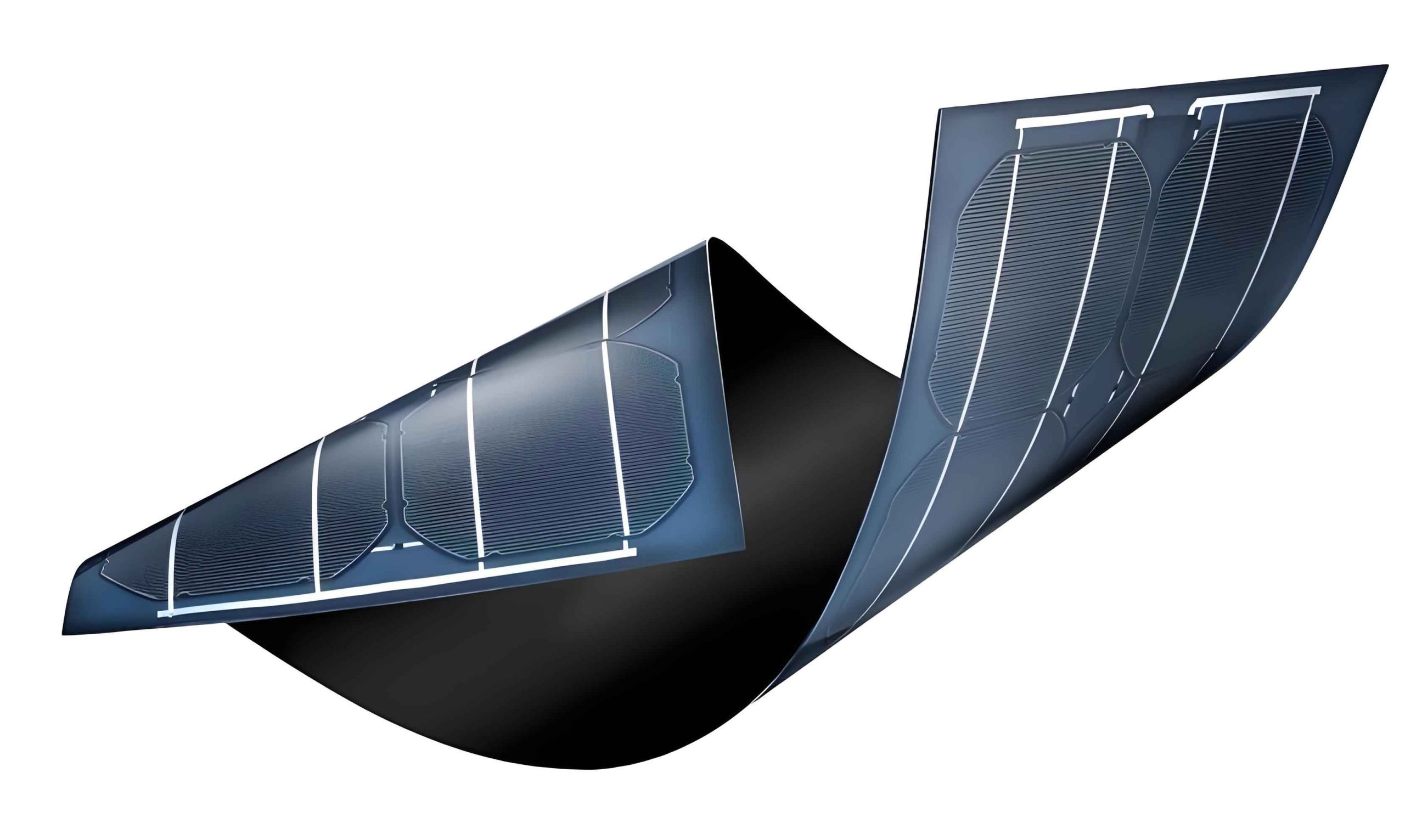
In my research, I focus on advancing thin film solar panels, which are pivotal for sustainable energy due to their low cost, flexibility, and potential for high efficiency. Among various absorber materials, tin sulfide (SnS) stands out as a promising candidate for thin film solar panels because of its optimal bandgap, high absorption coefficient, and environmentally benign composition. However, the efficiency of SnS-based thin film solar panels remains below theoretical limits, prompting investigations into device optimization through numerical simulation. In this study, I explore the role of a titanium dioxide (TiO2) buffer layer in enhancing the performance of SnS thin film solar panels, using the SCAPS software for detailed analysis. This work aims to provide insights into parameter tuning that can lead to more efficient thin film solar panels, contributing to the broader field of photovoltaic technology.
Thin film solar panels typically consist of multiple layers, including an absorber layer, buffer layer, and window layer, each critical for light absorption, charge separation, and carrier collection. For SnS-based thin film solar panels, the heterojunction with a buffer layer like TiO2 is essential for reducing recombination and improving open-circuit voltage. My simulation model involves a structure of Mo/SnS/TiO2/ZnO:Al, where Mo serves as the back contact, SnS as the p-type absorber, TiO2 as the n-type buffer, and ZnO:Al as the transparent conducting oxide window. The parameters for these layers are derived from literature and theoretical estimates, as summarized in Table 1. I use standard AM1.5 illumination at 300 K, with series and shunt resistances set to 4.25 Ω·cm² and 400 Ω·cm², respectively, to mimic real-world conditions in thin film solar panels.
| Parameters | SnS | TiO2 | ZnO:Al |
|---|---|---|---|
| Thickness (nm) | 2000 | 50 | 200 |
| Band gap energy (eV) | 1.3 | 3.2 | 3.3 |
| Electron affinity (eV) | 4.2 | 4.2 | 4.4 |
| Relative permittivity | 13 | 9 | 9 |
| Effective conduction band density (cm⁻³) | 1.18×10¹⁸ | 2.2×10¹⁸ | 2.2×10¹⁸ |
| Effective valence band density (cm⁻³) | 4.76×10¹⁸ | 1.80×10¹⁹ | 1.80×10¹⁹ |
| Electron mobility (cm²V⁻¹s⁻¹) | 30 | 100 | 100 |
| Hole mobility (cm²V⁻¹s⁻¹) | 90 | 25 | 25 |
| Donor density (cm⁻³) | – | 1×10¹⁷ | 1×10²⁰ |
| Acceptor density (cm⁻³) | 1.0×10¹⁵ | – | – |
| Defect density (cm⁻³) | 1.0×10¹⁴ | 1.0×10¹⁶ | 1.0×10¹⁸ |
The energy band diagram of the thin film solar panel, as shown in my simulation, reveals key insights into carrier transport. For the SnS/TiO2 heterojunction, the conduction band offset (ΔE_C) is 0 eV, while the valence band offset (ΔE_V) is 1.9 eV, calculated as:
$$ \Delta E_C = \chi_{\text{SnS}} – \chi_{\text{TiO2}} = 4.2 \, \text{eV} – 4.2 \, \text{eV} = 0 \, \text{eV} $$
$$ \Delta E_V = E_{g,\text{TiO2}} – E_{g,\text{SnS}} – \Delta E_C = 3.2 \, \text{eV} – 1.3 \, \text{eV} – 0 \, \text{eV} = 1.9 \, \text{eV} $$
This band alignment facilitates electron transport from the SnS absorber to the TiO2 buffer while blocking holes, thereby enhancing charge separation in thin film solar panels. The large ΔE_V reduces hole recombination at the interface, a common issue in thin film solar panels that limits efficiency.
In my analysis, I first investigate the impact of SnS absorber layer thickness on the performance of thin film solar panels. Varying the thickness from 0.5 to 3.0 μm, I observe that the short-circuit current density (J_SC) and open-circuit voltage (V_OC) increase initially but saturate beyond 2 μm, as summarized in Table 2. The fill factor (FF) peaks at 0.75 μm before declining due to increased series resistance. This behavior is critical for designing cost-effective thin film solar panels, as thicker layers raise material costs without significant efficiency gains. The quantum efficiency (QE) analysis, represented by the equation:
$$ QE(\lambda) = \frac{J_{SC}(\lambda)}{e \cdot \Phi(\lambda)} $$
where e is the electron charge and Φ is the photon flux, shows enhanced absorption at longer wavelengths with thicker SnS, but the trade-off with carrier collection must be balanced. For thin film solar panels, an optimal SnS thickness of around 2 μm is identified, yielding a J_SC of 31.56 mA/cm² and V_OC of 822.45 mV in my simulation.
| SnS Thickness (μm) | V_OC (mV) | J_SC (mA/cm²) | FF (%) | Efficiency (%) |
|---|---|---|---|---|
| 0.5 | 780.2 | 25.34 | 58.1 | 11.45 |
| 1.0 | 810.5 | 29.87 | 59.8 | 14.47 |
| 1.5 | 820.1 | 31.02 | 60.0 | 15.26 |
| 2.0 | 822.5 | 31.56 | 60.3 | 15.66 |
| 2.5 | 823.0 | 31.78 | 59.9 | 15.68 |
| 3.0 | 823.2 | 31.85 | 59.5 | 15.65 |
Next, I examine the doping concentration of the SnS absorber in thin film solar panels. By varying the acceptor density from 10¹⁴ to 10¹⁷ cm⁻³, I find that V_OC increases with doping due to a stronger built-in field, while J_SC remains stable until it drops at higher concentrations owing to enhanced bulk recombination. The efficiency peaks at a doping level of 10¹⁶ cm⁻³, reaching 15.66%. This optimization is vital for thin film solar panels, as it balances carrier generation and transport. The relationship between doping and carrier concentration can be expressed using the charge neutrality equation:
$$ p = N_A – n + \sqrt{\frac{N_A^2}{4} + n_i^2} $$
where p is the hole concentration, N_A is the acceptor density, n is the electron concentration, and n_i is the intrinsic carrier density. For thin film solar panels, controlling doping is key to minimizing recombination losses.
Turning to the TiO2 buffer layer, its thickness and doping significantly influence thin film solar panel performance. As shown in Table 3, increasing TiO2 thickness from 10 to 100 nm reduces J_SC and efficiency because thicker buffers absorb more short-wavelength light and increase carrier recombination paths. An optimal thickness of 50 nm is chosen for practical fabrication of thin film solar panels. Similarly, varying the donor density from 10¹⁴ to 10¹⁹ cm⁻³ reveals that higher doping (above 10¹⁷ cm⁻³) improves J_SC and FF by enhancing the electric field, but beyond 10¹⁷ cm⁻³, gains plateau due to trap-assisted recombination. This underscores the importance of buffer layer engineering in thin film solar panels for achieving high efficiency.
| TiO2 Thickness (nm) | V_OC (mV) | J_SC (mA/cm²) | FF (%) | Efficiency (%) |
|---|---|---|---|---|
| 10 | 824.0 | 32.10 | 61.0 | 16.15 |
| 30 | 822.8 | 31.80 | 60.5 | 15.85 |
| 50 | 822.5 | 31.56 | 60.3 | 15.66 |
| 70 | 822.0 | 31.30 | 60.0 | 15.42 |
| 100 | 821.5 | 31.00 | 59.8 | 15.20 |
For thin film solar panels, operational stability under varying temperatures is crucial. My simulation of temperature effects from 280 to 360 K shows that V_OC and efficiency decrease with rising temperature, while J_SC slightly increases due to bandgap narrowing. The temperature coefficient of efficiency is calculated as -0.029%/K, indicating that thin film solar panels based on SnS/TiO2 are sensitive to thermal changes. This coefficient can be derived from the diode equation:
$$ V_{OC} = \frac{n k T}{e} \ln\left(\frac{J_{SC}}{J_0} + 1\right) $$
where n is the ideality factor, k is Boltzmann’s constant, T is temperature, and J_0 is the reverse saturation current. For thin film solar panels, cooling strategies may be necessary to maintain performance in hot climates.
Another critical aspect for thin film solar panels is the back contact metal work function. I simulate work functions from 4.4 to 5.4 eV and find that efficiency improves sharply until 5.1 eV, after which it stabilizes. At 4.4 eV, a Schottky barrier forms, hindering hole collection, while higher work functions create an ohmic contact, as illustrated by the band bending equation:
$$ \phi_b = \phi_m – \chi_s $$
where φ_b is the barrier height, φ_m is the metal work function, and χ_s is the semiconductor electron affinity. For thin film solar panels, selecting a back contact with φ_m > 5.1 eV, such as platinum or gold, can boost efficiency to 16.83% in my model.
After optimizing all parameters, my simulated thin film solar panel achieves an efficiency of 15.66% with V_OC = 822.45 mV, J_SC = 31.56 mA/cm², and FF = 60.32%. The current-density-voltage (J-V) characteristic, shown in Figure 1, demonstrates good diode behavior with minimal recombination. This performance highlights the potential of SnS/TiO2 heterojunctions in thin film solar panels, though further improvements via defect passivation or interface engineering could push efficiencies closer to the theoretical limit of 24%.
In conclusion, my numerical study provides a comprehensive framework for optimizing thin film solar panels using SnS absorbers and TiO2 buffer layers. Through parameter tuning, I demonstrate that thin film solar panels can achieve high efficiency by balancing absorber thickness, doping concentrations, buffer properties, temperature resilience, and contact engineering. These findings offer valuable guidance for researchers and manufacturers aiming to develop next-generation thin film solar panels with enhanced performance and sustainability. Future work will involve experimental validation and exploration of alternative materials to further advance thin film solar panels for global energy solutions.
To summarize key formulas used in this analysis for thin film solar panels, I list them below:
1. Quantum efficiency: $$ QE(\lambda) = \frac{J_{SC}(\lambda)}{e \cdot \Phi(\lambda)} $$
2. Conduction band offset: $$ \Delta E_C = \chi_{\text{SnS}} – \chi_{\text{TiO2}} $$
3. Valence band offset: $$ \Delta E_V = E_{g,\text{TiO2}} – E_{g,\text{SnS}} – \Delta E_C $$
4. Charge neutrality: $$ p = N_A – n + \sqrt{\frac{N_A^2}{4} + n_i^2} $$
5. Open-circuit voltage: $$ V_{OC} = \frac{n k T}{e} \ln\left(\frac{J_{SC}}{J_0} + 1\right) $$
6. Schottky barrier height: $$ \phi_b = \phi_m – \chi_s $$
These equations are fundamental for modeling and improving thin film solar panels, and they underscore the interdisciplinary nature of photovoltaic research. As thin film solar panels continue to evolve, numerical simulations like mine will play a pivotal role in accelerating innovation and deployment in renewable energy systems.