
The modular multilevel converter battery energy storage system (MMC BESS) has AC/DC interfaces and has received widespread attention in the fields of new energy generation energy storage systems, DC microgrids, AC/DC interconnection, and electric vehicle charging in recent years.
The MMC structure was first successfully applied in the field of flexible direct current transmission (MMC-HVDC), where the inter phase circulation forms complex current voltage coupling between the three phases, resulting in complex frequency components of the circulation. The circulating current causes a decrease in the control performance of the converter, a decrease in the output power quality, and an increase in losses. Many scholars have conducted in-depth research on the mechanism of MMC-HVDC circulation and its suppression strategies.
Modular multilevel converter battery energy storage system applies MMC structure to battery energy storage, with single stage structure being the focus of research due to its simple control, low cost, and high efficiency. Due to the addition of energy storage batteries, their inter phase circulation is different from that of MMC-HVDC.
This article conducts in-depth research and analysis on the generation mechanism of modular multilevel converter battery energy storage system interphase circulation, and conducts experimental verification.
1.Modular multilevel converter battery energy storage system topology and experimental platform
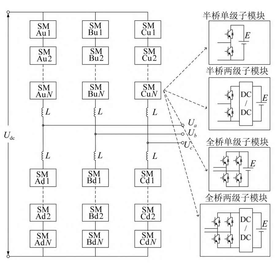
The basic units that make up modular multilevel converter battery energy storage system are sub modules (SM). modular multilevel converter battery energy storage system has three phase clusters, each with two bridging arms, upper and lower. Each bridge arm is composed of N sub modules and 1 bridge arm inductor connected in series. The typical modular multilevel converter battery energy storage system topology is shown in Figure 1.
The research is based on a half bridge single stage modular multilevel converter battery energy storage system experimental platform, and its parameters are shown in Table 1.
2.Analysis of the mechanism of inter phase circulation
The reasons for the inter phase circulation include three aspects: voltage fluctuations on the DC side of the submodule, inconsistent driving signals, and inconsistent voltage drop of the switch tube.
2.1 Voltage fluctuation on the DC side of the submodule
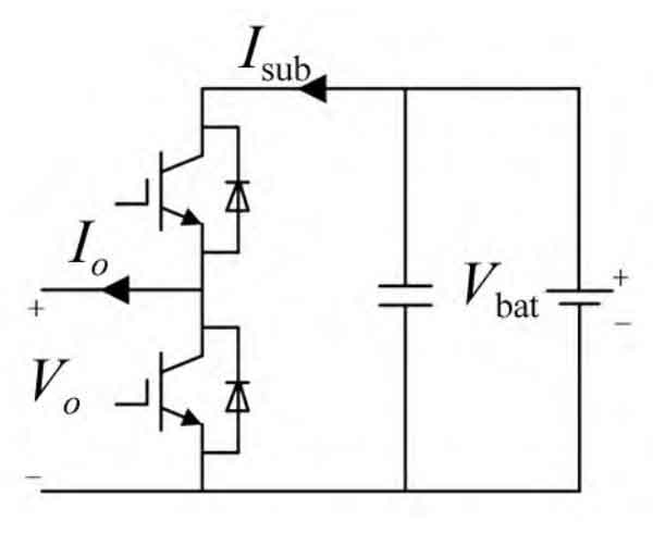
According to the positive direction defined in Figure 2, analyze the frequency component of the DC side current of the submodule based on energy balance. Figure 2: Isub represents the DC side current of the submodule; Vbat is the battery voltage; Io is the output current of the submodule; Vo is the output voltage of the submodule.
| Parameters | Value |
| AC side phase voltage Ua, b, c/V | 28.5 |
| Number of bridge arm submodules N/piece | 85.8 |
| DC side voltage Udc/V | 12 |
| Number of system sub modules 6N/piece | 33 |
| Sub module battery nominal voltage Ubat/V | 8 |
| Bridge arm inductance La/mH | 48 |
| Sub module nominal capacity CN/Ah | 0.1 |
| Grid connected inductance Lg/mH | 0.2 |
Within a power frequency cycle, the battery voltage can be considered constant, considering only the DC and fundamental components of the output current. Based on energy conservation, there are:
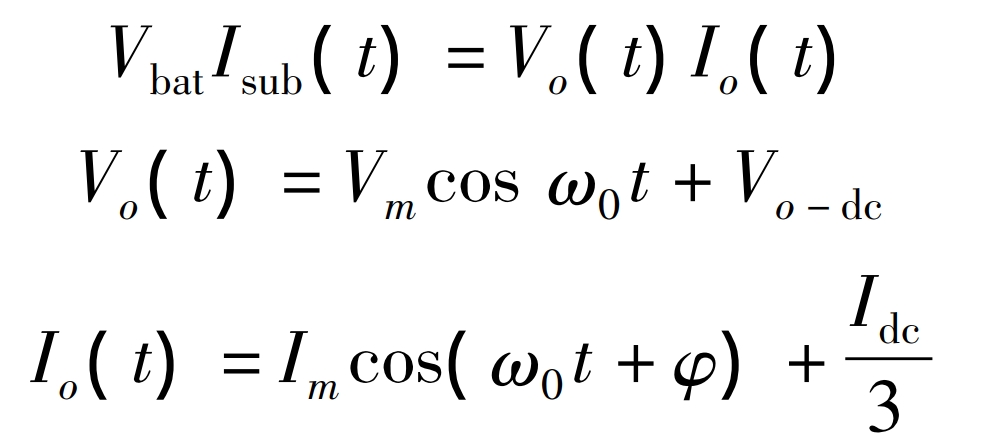
Based on the above three formulas, it can be inferred that:
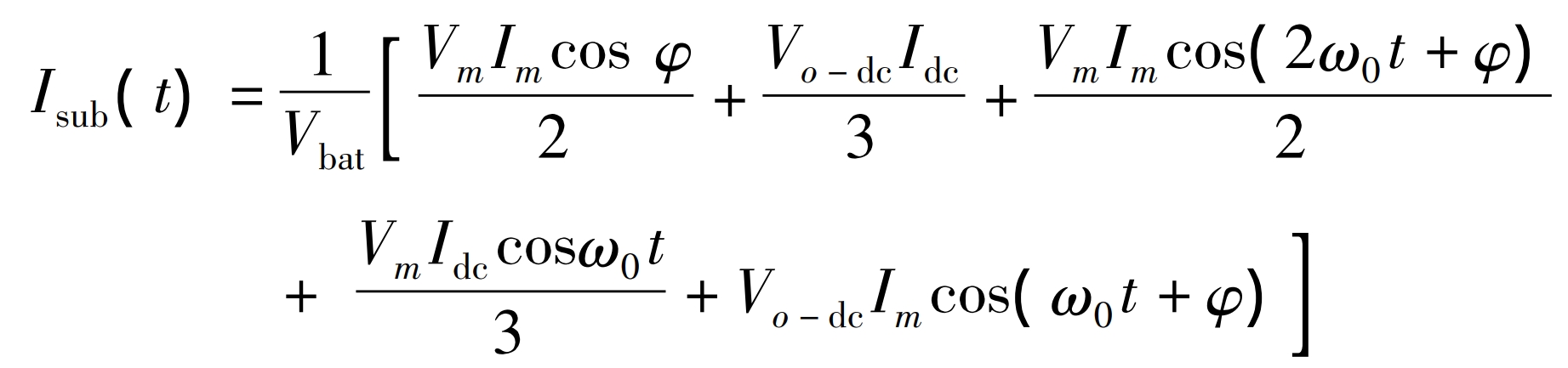
In the formula, Vm and Im are the amplitude of the power frequency voltage component and the amplitude of the power frequency current component output by the submodule, respectively; φ Is the phase difference between the two; ω 0 is the power frequency angular frequency; Vo-dc is the DC voltage component output by the submodule; Idc is the total DC grid connected current of modular multilevel converter battery energy storage system. Equation (4) indicates that the DC side current of the single-stage modular multilevel converter battery energy storage system submodule consists of three parts: DC component, fundamental component, and second harmonic component.
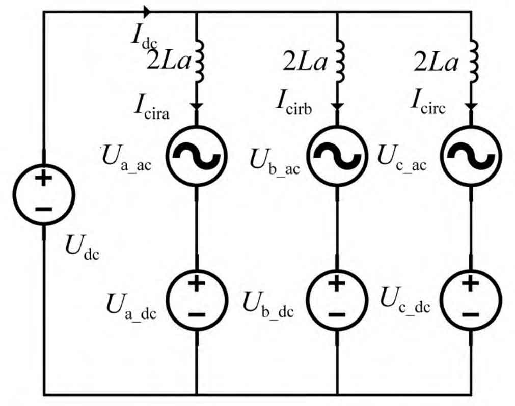
The modular multilevel converter battery energy storage system circulating current equivalent circuit is shown in Figure 3.
In Figure 3, Icira, Icirb, and Icirc represent the circulating currents of the ABC three-phase system, respectively; Ua_ Ac, Ub_ Ac and Uc_ Ac represents the total equivalent power frequency voltage of ABC three-phase submodules; Ua_ DC, Ub_ DC and Uc_ DC represents the total equivalent DC voltage of ABC three-phase submodules.
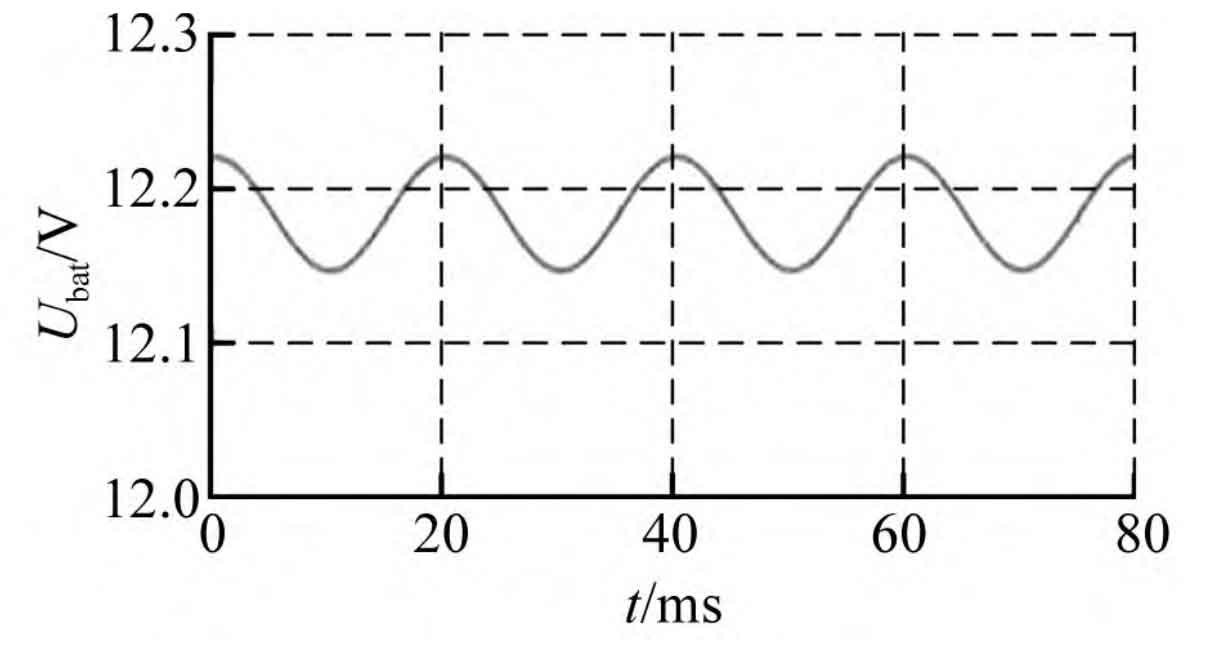
Due to the small internal resistance of the battery, the voltage double fundamental frequency fluctuation caused by the second harmonic current on the DC side of the submodule is not significant. Taking the test platform 12 V/33 Ah lead-acid battery as an example, its standard internal resistance is 8.4 m Ω, and the parallel capacitance value of the battery is 3000 μ F. Using the Simulink battery model for simulation, under the action of a peak 10 A double frequency AC current, the output voltage fluctuation of the submodule is 7.28 mV, and its waveform is shown in Figure 4.
Calculated with a voltage fluctuation of 7.28 mV and 16 sub modules per phase, the phase voltage fluctuates twice in frequency Δ U is 0.116 V, ignoring the influence of internal resistance in the circuit, and calculating the second harmonic circulating current between phases Δ I.
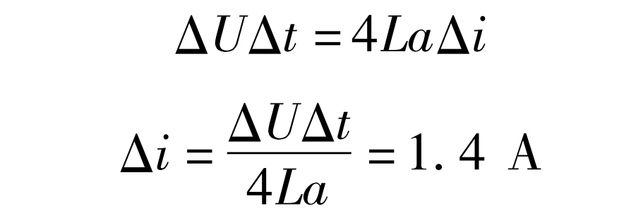
In the formula: La is the bridge arm inductance, and La is taken as 0.1 mH; Δ T is half a second harmonic period, taken as 5 ms. The calculated peak of the second harmonic circulation is 1.46 A, accounting for 14.6% of the AC peak.
2.2 Inconsistent Drive Signal
Inconsistent driving signals include two aspects: inconsistent driving time caused by inconsistent communication delay in the internal control system of the phase, and inconsistent driving signal timing between the three phases. Inconsistent driving signals within a phase cluster can cause fluctuations in the total voltage of the phase cluster, resulting in inconsistent total voltage of the phase cluster and ultimately leading to inter phase circulation. Improving the system communication speed and increasing the inductance of the bridge arm can effectively reduce the magnitude of inter phase circulation caused by this factor.
The reason for the inconsistent driving signals between the three phases is that the DC power control is calculated by three independent PI controllers for the three-phase voltage reference value, and the DC reference voltage output by the three independent controllers is inevitably not completely consistent. After being converted into sub module switch signals through modulation algorithms, there will inevitably be instantaneous inequality in the total voltage of the phase cluster.
Modeling and simulation were conducted on the experimental platform to obtain the instantaneous changes in the number of A-phase input submodules NA, B-phase input submodules NB, and the difference between the two (NA NB) over time, as shown in Figure 5.
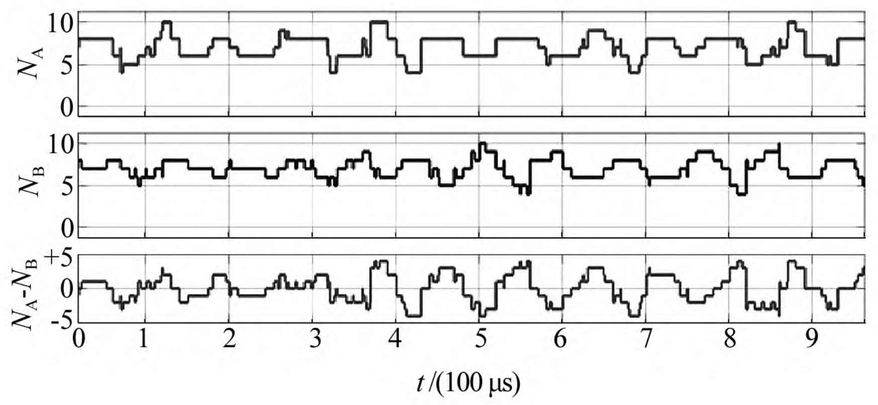
It can be seen that NA and NB are inconsistent for most of the time, with the difference fluctuating between -4 and 4. This causes fluctuations in the total voltage of the phase cluster related to the switching frequency, causing inter phase circulation. Due to the strong suppression effect of inductance on switching frequency in the circuit, the circulating current is very small.
2.3 Inconsistent switch device parameters
Inconsistent switch device parameters include inconsistent on/off voltage drop and on/off time of switch tubes, and their impact on inter phase circulation is also the fluctuation of switch frequency. Due to the small inconsistency of switch device parameters and the fact that the impact of sub module switch device parameter inconsistency can be offset to some extent between phases, the impact on inter phase circulation is also minimal.
3.Suppression strategies for inter phase circulation
On the basis of studying the circulation mechanism, targeted suppression of the inter phase circulation of modular multilevel converter battery energy storage system can be carried out.
3.1 Suppressing the negative sequence circulation of the second harmonic generation
For the second harmonic fluctuation of the DC side voltage of the submodule, a circulating current suppression controller similar to that in the MMC-HVDC system is adopted to suppress it.
The internal circulation of the three-phase is calculated from the current of the upper and lower bridge arms, and the inter phase circulation value is obtained by subtracting the DC current. The dq axis component of the inter phase circulation is obtained through the double frequency negative sequence coordinate transformation. After feedforward decoupling and PI controller, the target values of the d-axis and q-axis of the double frequency negative sequence circulation are controlled to 0. The structure of the inter phase circulation suppression controller is shown in Figure 6.
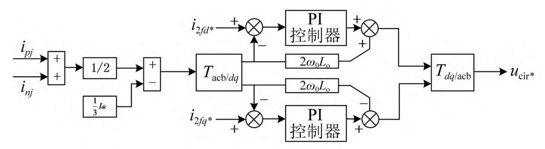
In Figure 6, ipj and inj represent the upper and lower bridge arm currents of phase j, respectively; I2fd * and i2fq * are the current command values for the d-axis and q-axis of the second harmonic generation, respectively; Ucir * is the command value of the 2-fold frequency circulating current suppression voltage.
3.2 Suppression of power frequency inter phase circulation
The phase of power frequency voltage fluctuations in the upper and lower bridge arms is opposite. Due to inconsistent internal resistance and other reasons, the amplitude of power frequency voltage fluctuations in the upper and lower bridge arms varies, which will cause inter phase power frequency circulation. At present, the control strategy of modular multilevel converter battery energy storage system is based on the assumption that the power frequency current flowing through the upper and lower bridge arms is equally divided, so it is impossible to suppress the power frequency circulation from the control strategy. Measures can only be taken from the perspective of maintaining the consistency of sub module parameters. Try to maintain consistency in battery parameters between the upper and lower bridge arms during design and selection; Secondly, during system operation, bridge arm balancing control is carried out to maintain the upper and lower bridge arms in the same SOC state, indirectly suppressing power frequency inter phase circulation.
3.3 Suppression of high-frequency interphase circulation
The bridge arm inductance can suppress high-frequency inter phase circulation caused by factors such as inconsistent driving signals and inconsistent switching device parameters. The inductance value of the bridge arm selected according to the principles of grid connection and short-circuit action can meet the requirements of suppressing high-frequency inter phase circulation.
4.Experimental verification of inter phase circulation
Analyze the mechanism of interphase circulation and conduct tests on the experimental platform.
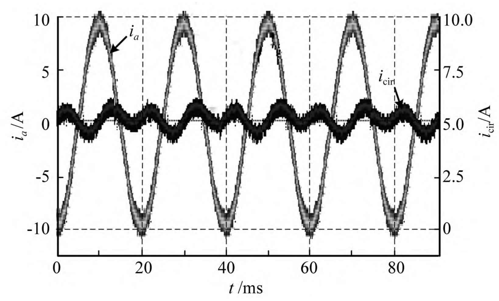
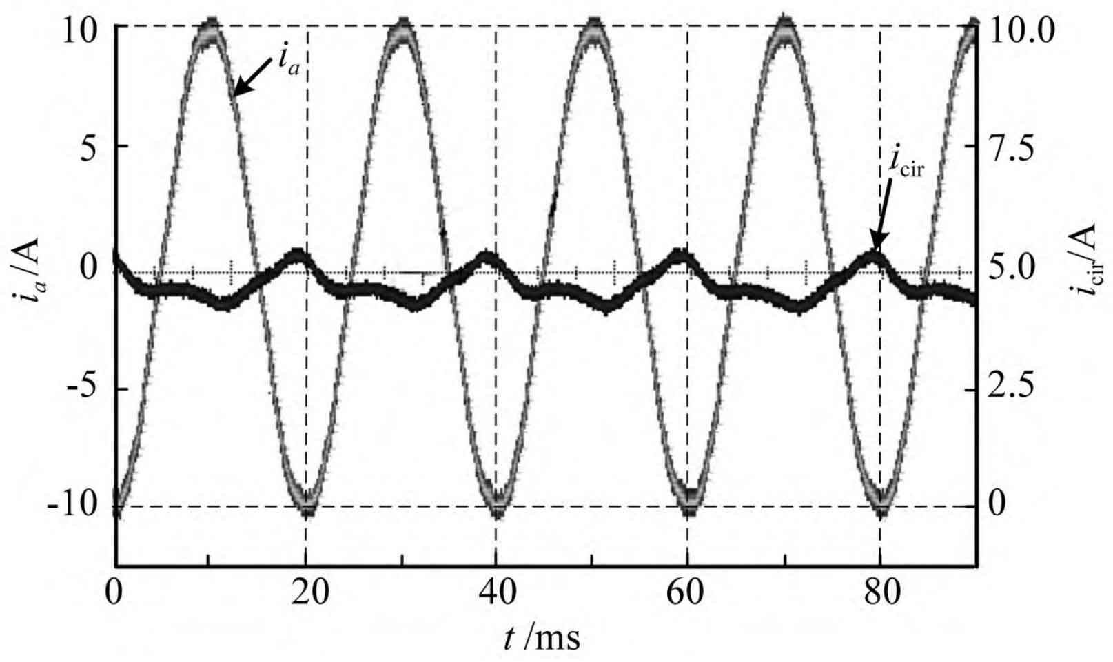
Set the SOC of each submodule battery to be the same through the battery charging and discharging instrument, and conduct phase to phase circulating current testing. The results are shown in Figure 7. In the case of a phase current peak of 10 A, there is a circulation and a significant second harmonic fluctuation, with a peak fluctuation of 0.8 A, which is smaller than the calculated value in section 2.1. The main reason is that the calculated values in section 2.1 ignore the influence of battery internal resistance, wire and contact resistance. Then charge and discharge each phase submodule battery to achieve a discrete distribution of SOC in each phase, and test the inter phase circulation. The results are shown in Figure 8. It can be seen that the inter phase circulation is the superposition of the second harmonic component and the fundamental component, which is completely consistent with the simulated waveform.
5.Conclusion
The circulation mechanism and suppression of modular multilevel converter battery energy storage system were studied, and the expression for the DC current of the submodule was derived. The fluctuation pattern of the total voltage of the phase cluster with the current was obtained. Analysis and research indicate that:
(1) The second harmonic fluctuation of battery voltage caused by the DC side current of the submodule will result in phase to phase second harmonic circulation, which can be suppressed by similar methods as in MMC-HVDC.
(2) Inconsistent parameters between the upper and lower bridge arms will cause inter phase power frequency circulation, which cannot be directly eliminated through control.
(3) Inconsistent driving signals and inconsistent switching device parameters have a small impact on interphase circulation and can be ignored.