
In the realm of aviation safety, airport navigation lighting systems play a critical role by providing visual guidance for aircraft during nighttime operations or under low-visibility conditions. As an engineer specializing in airport operations, I have observed that power supply interruptions in these systems can severely impact flight safety. Current standards, such as those outlined in aviation technical specifications, mandate that critical lighting circuits, like those in Category II/III precision approach lighting systems, must achieve power source switching within one second. Traditionally, airports rely on a dual utility power supply complemented by diesel generators and Uninterruptible Power Supply (UPS) systems. However, in practice, UPS units are only briefly engaged during transitions between utility power and generators, leading to underutilization of their energy storage components and a disproportionate cost relative to their function. This inefficiency has prompted me to explore integrating solar photovoltaic (PV) power generation into airport navigation lighting supply systems. By designing a combined photovoltaic and energy storage solution, we can provide an additional layer of power security, meet the stringent one-second switching requirement, and contribute to airport energy conservation and emission reduction goals. This article delves into this innovative approach, offering new perspectives and research directions for airport power system design.
The current airport navigation lighting power supply infrastructure typically involves two independent utility power feeds arranged in a single busbar segmentation configuration. Under normal conditions, these feeds operate in parallel with a bus tie breaker open, ensuring mutual backup. Additionally, diesel generators are installed based on maximum power demand to serve as emergency sources during utility failures. To comply with the one-second power transition mandate—defined as the time for light intensity to drop to 50% and recover to 50% during a source switch—many airports incorporate UPS systems. Online UPS units work by rectifying utility AC to DC, which then powers an inverter to supply AC to loads; during utility outages, batteries support the inverter, ensuring uninterrupted output. However, UPS systems are rarely activated except during power failures, and their batteries require periodic manual discharge cycles, leading to low utilization rates, significant degradation, and high maintenance costs relative to their operational role. This setup highlights a need for more efficient and sustainable alternatives.
Solar photovoltaic power generation harnesses the photovoltaic effect at semiconductor interfaces to convert sunlight directly into electricity. This technology offers a clean, renewable energy source that aligns with global energy transition trends. Airports, as large-scale energy consumers operating around the clock, present ideal conditions for solar system deployment. Navigation lighting substations are often located at runway ends, surrounded by open, unobstructed areas that receive ample sunlight. These zones provide ample space for installing solar panels, and support structures can be designed with frangible mounts to meet aviation safety requirements for objects in flight areas, ensuring they break away easily upon impact. Notably, several airports worldwide have already implemented solar photovoltaic systems, demonstrating their feasibility in aviation environments. For instance, a major international airport installed a distributed photovoltaic generation project near its runway, using advanced monocrystalline silicon modules positioned close to the runway centerline without causing glare or visual distractions for pilots. This validates that solar systems can be integrated into airport peripherals with proper design.
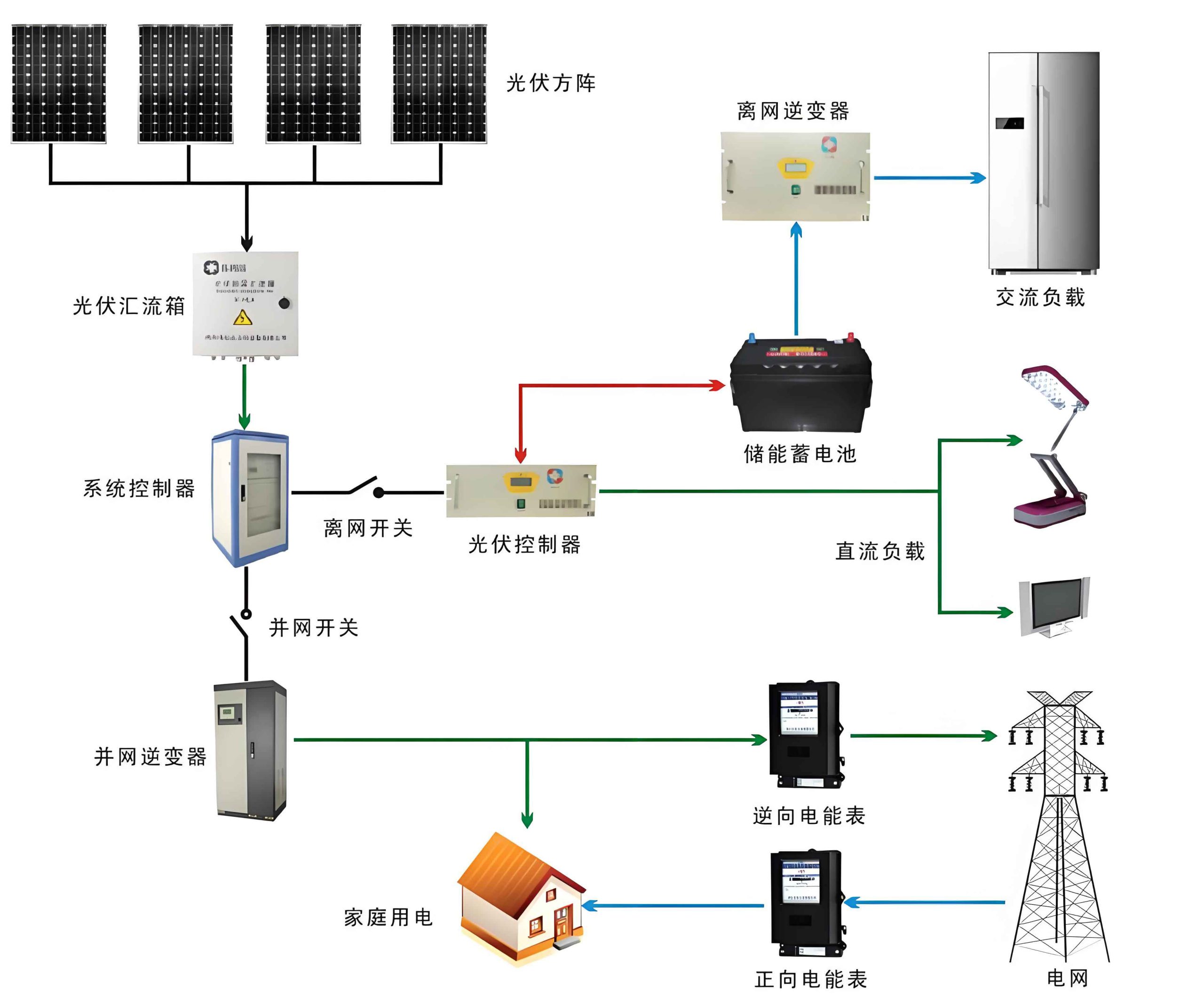
Integrating solar photovoltaic power into airport navigation lighting supply systems offers multifaceted advantages over the conventional utility-generator-UPS model. A distributed solar system, combined with energy storage, can enhance power reliability while promoting节能减排. During daylight hours, the solar system can directly power navigation lighting loads, with excess energy charging storage batteries. At night or during low-visibility conditions, the stored energy can supply the loads, reducing dependence on utility power. Moreover, by leveraging energy storage for peak shaving and valley filling, airports can optimize electricity costs—charging batteries during off-peak, low-tariff periods and discharging them during peak, high-tariff times. This economic benefit, coupled with the environmental gains from renewable energy, makes the solar system a compelling addition. Crucially, advanced solar systems with integrated storage can facilitate seamless power switching through current inversion control, adjusting parameters like load, phase angle, and losses to enable uninterrupted transitions between utility and solar power, thereby meeting the one-second switching requirement and enhancing operational safety.
The overall design for incorporating solar photovoltaic power into airport navigation lighting supply systems involves a hybrid approach that integrates utility power, solar generation, and energy storage. Based on typical design standards for distributed photovoltaic grid connections, the solar system can be connected at a single point to the low-voltage side of the lighting substation, using a 380V voltage level compatible with transformer capacity and system parameters. In this configuration, utility power (Q1) and solar power (Q3) jointly supply the loads, with a diesel generator (Q2) as backup. A static transfer switch (STS) ensures instantaneous switching between sources. When sunlight is abundant, the solar system powers the loads and charges the storage; during insufficient sunlight, the system seamlessly switches to utility power. Conversely, if utility power fails, it switches to storage, and if storage is depleted, it transitions to the generator. This hybrid system maximizes stability and reliability.
Energy storage is a critical component, given that navigation lighting operates continuously and solar generation is intermittent. The storage system primarily serves as a safety backup, with an initial battery capacity designed to supply power for one hour (adjustable based on actual load calculations). Additionally, it enables cost savings through peak shaving. For example, in regions with time-of-use electricity tariffs, a two-charge-two-discharge strategy can be implemented, leveraging off-peak hours for charging and peak hours for discharging. The table below outlines a sample charging and discharging strategy for a storage system:
| Time Period | Off-Peak (23:00-07:00) | Peak (09:00-12:00) | Standard (12:00-16:00) | Peak (16:00-21:00) |
|---|---|---|---|---|
| Storage System Operation | Charging | Discharging | Charging | Discharging |
A solar-plus-storage integrated unit, or “solar system,” combines photovoltaic generation and storage into a compact, efficient device. It typically includes DC/DC modules, bidirectional energy storage converters, and an STS. For instance, consider an airport lighting substation requiring one-second switching for specific lighting circuits. Based on load analysis, multiple sets of 100 kW/215 kWh storage systems can be deployed, each comprising a 100 kW integrated solar system unit and a 215 kWh DC storage cabinet. These units are paralleled on the AC side and connected to the UPS input lines. The system’s Energy Management System (EMS) monitors real-time data, enabling remote control and automated operation. The storage cabinet integrates lithium batteries, communication modules, thermal control, fire detection, and safety systems, ensuring reliable performance. The topology for integrating these solar systems is illustrated in the design schematic, where STS switches facilitate rapid transitions during power faults.
To delve deeper into the technical aspects, the power output of a solar photovoltaic system can be modeled using the photovoltaic effect equation. The current-voltage characteristic of a solar cell is given by:
$$ I = I_{ph} – I_0 \left( \exp\left(\frac{q(V + IR_s)}{nkT}\right) – 1 \right) – \frac{V + IR_s}{R_{sh}} $$
where \( I \) is the output current, \( I_{ph} \) is the photocurrent, \( I_0 \) is the reverse saturation current, \( q \) is the electron charge, \( V \) is the output voltage, \( R_s \) is the series resistance, \( n \) is the ideality factor, \( k \) is Boltzmann’s constant, \( T \) is the temperature in Kelvin, and \( R_{sh} \) is the shunt resistance. For a solar array comprising multiple cells, the total power \( P_{pv} \) under standard test conditions can be approximated as:
$$ P_{pv} = N_{series} \times N_{parallel} \times V_{mp} \times I_{mp} \times \eta_{pv} $$
where \( N_{series} \) and \( N_{parallel} \) are the numbers of cells in series and parallel, \( V_{mp} \) and \( I_{mp} \) are the voltage and current at maximum power point, and \( \eta_{pv} \) is the photovoltaic efficiency. This formula helps in sizing the solar system for airport applications.
Energy storage systems, particularly battery banks, are essential for smoothing solar power variability. The state of charge (SOC) of a battery can be expressed as:
$$ SOC(t) = SOC(0) + \frac{1}{C} \int_0^t \eta_{ch} I_{ch}(\tau) \, d\tau – \frac{1}{C} \int_0^t \frac{I_{dis}(\tau)}{\eta_{dis}} \, d\tau $$
where \( C \) is the battery capacity in ampere-hours, \( \eta_{ch} \) and \( \eta_{dis} \) are charging and discharging efficiencies, and \( I_{ch} \) and \( I_{dis} \) are charging and discharging currents. For lithium-ion batteries commonly used in solar systems, the depth of discharge (DOD) affects lifespan, often modeled as:
$$ L = L_0 \times \left( \frac{DOD}{DOD_0} \right)^{-k} $$
where \( L \) is the cycle life, \( L_0 \) is the reference cycle life at reference depth of discharge \( DOD_0 \), and \( k \) is a degradation coefficient. These equations guide the design of reliable storage for navigation lighting.
The economic viability of integrating a solar system into airport power infrastructure can be assessed through cost-benefit analysis. The net present value (NPV) of the solar system investment is calculated as:
$$ NPV = \sum_{t=1}^{T} \frac{C_t}{(1 + r)^t} – C_0 $$
where \( C_t \) are the net cash flows in year \( t \), \( r \) is the discount rate, \( T \) is the project lifetime, and \( C_0 \) is the initial investment. Cash flows include savings from reduced utility consumption, peak shaving benefits, and maintenance cost reductions. For example, if a solar system reduces annual electricity costs by \( S \) and has annual operating costs \( O \), the payback period \( P \) can be estimated as:
$$ P = \frac{C_0}{S – O} $$
Additionally, the levelized cost of energy (LCOE) for the solar system is:
$$ LCOE = \frac{\sum_{t=1}^{T} \frac{I_t + M_t}{(1 + r)^t}}{\sum_{t=1}^{T} \frac{E_t}{(1 + r)^t}} $$
where \( I_t \) is investment cost in year \( t \), \( M_t \) is maintenance cost, and \( E_t \) is energy generated. Comparing LCOE with utility tariffs demonstrates long-term savings.
To illustrate system sizing, consider an airport navigation lighting load profile. Suppose the total power demand for circuits requiring one-second switching is 210 kVA, as detailed in the table below. This data informs the design of the solar and storage components.
| Lighting Circuit | Load (kVA) | Notes |
|---|---|---|
| Approach Lighting 1 | 20 | Category II/III critical |
| Runway Edge Lights 2 | 25 | HUD-compatible |
| Runway Centerline Lights 2 | 15 | Precision approach |
| Threshold Wing Bars 3 | 15 | Entry guidance |
| Stop Bars 1-6 | 5 each | Taxiway control |
| Touchdown Zone Lights 1 | 10 | Landing zone |
| Backup Lighting 4 | 30 | Emergency |
| Backup Lighting 5 | 20 | Emergency |
| Backup Lighting 6 | 30 | Emergency |
| Total Load | 210 kVA | Sum of all circuits |
Based on this load, a solar system with photovoltaic panels rated at, for instance, 300 kWp (kilowatt-peak) could be installed, considering local solar irradiance. Assuming an average daily irradiance of 4.5 kWh/m² and panel efficiency of 20%, the energy generated daily \( E_{daily} \) is:
$$ E_{daily} = P_{pv} \times H_{sun} \times \eta_{system} $$
where \( P_{pv} = 300 \, \text{kW} \), \( H_{sun} = 4.5 \, \text{h} \) (equivalent sun hours), and \( \eta_{system} = 0.85 \) (system efficiency including inverters and losses). Thus,
$$ E_{daily} = 300 \times 4.5 \times 0.85 = 1147.5 \, \text{kWh} $$
This generation can power the lighting loads during daylight and charge storage for nighttime use. The storage capacity required for one hour of backup at 210 kVA with a power factor of 0.9 is:
$$ E_{storage} = P \times t = (210 \times 0.9) \, \text{kW} \times 1 \, \text{h} = 189 \, \text{kWh} $$
Hence, a 215 kWh battery bank, as mentioned earlier, provides adequate reserve.
Safety and reliability are paramount in airport operations. The solar system design must account for factors like electromagnetic interference, lightning protection, and physical resilience. Frangible mounts for solar panels ensure they do not pose hazards to aircraft. Moreover, the integrated EMS continuously monitors battery health, temperature, and voltage, triggering alarms for anomalies. Redundancy in the solar system, such as multiple inverters and bypass circuits, enhances uptime. The use of maximum power point tracking (MPPT) in photovoltaic controllers optimizes energy harvest, governed by:
$$ \frac{dP}{dV} = 0 $$
where \( P = VI \) is the power output. MPPT algorithms adjust operating points to maintain this condition under varying irradiance.
Environmental benefits of the solar system extend beyond cost savings. By displacing fossil fuel-based power, the solar system reduces carbon emissions. The annual CO₂ savings \( \Delta C \) can be estimated as:
$$ \Delta C = E_{solar} \times EF_{grid} $$
where \( E_{solar} \) is annual solar generation and \( EF_{grid} \) is the grid emission factor (e.g., 0.5 kg CO₂/kWh for many regions). For a 300 kWp solar system generating 1147.5 kWh daily, annual generation is approximately 418,837 kWh, yielding:
$$ \Delta C = 418,837 \times 0.5 = 209,418.5 \, \text{kg CO₂/year} $$
This contributes significantly to airport sustainability targets.
In conclusion, integrating solar photovoltaic power generation into airport navigation lighting supply systems offers a robust solution to enhance power reliability, meet stringent switching requirements, and achieve节能减排. The solar system, coupled with energy storage, provides a clean, renewable energy source that complements existing utility and generator setups. Through careful design—including low-voltage grid connection, optimized storage strategies, and integrated solar-plus-storage units—airports can ensure uninterrupted lighting operation while reducing operational costs and environmental impact. The technical analysis presented here, supported by formulas and tables, underscores the feasibility and benefits of this approach. As airports worldwide strive for greener operations, adopting solar systems for critical infrastructure like navigation lighting represents a forward-thinking step toward sustainable aviation. Future research could explore advanced materials for higher-efficiency panels, smart grid integration, and hybrid systems combining solar with other renewables, further solidifying the role of solar technology in airport energy management.