
As we move further into the 21st century, the adoption of renewable energy sources has become a critical focus in global development. Among these, solar energy stands out as a clean, efficient, and virtually inexhaustible resource. In my research and practical experience, I have explored the integration of photovoltaic (PV) technology with everyday infrastructure, such as parking shelters, to create multifunctional systems that harness solar power while providing utility. This article delves into the design and implementation of a solar system for photovoltaic carports, emphasizing structural components, electrical configurations, and performance optimization. The solar system concept here refers to the entire setup—from PV panels to support structures—that converts sunlight into electricity, and I will use this term repeatedly to highlight its centrality in modern energy solutions.
The project I am discussing involves retrofitting an existing outdoor parking area with a photovoltaic carport system. Located in a region with favorable solar insolation (approximately 120.9°E, 30.4°N), this initiative aims to address dual challenges: providing shaded parking for vehicles and facilitating charging for electric cars through on-site solar power generation. By leveraging underutilized spaces, such as parking lots, we can deploy solar systems that contribute to grid stability, reduce carbon footprints, and enhance user convenience. The solar system installed here has a total capacity of 231 kWp, comprising 416 monocrystalline silicon panels, each rated at 450 W. This integration exemplifies how solar systems can be seamlessly embedded into built environments, promoting sustainability without compromising functionality.
The core of this photovoltaic carport lies in its solar system components, which work in harmony to ensure efficient energy capture and durability. Below, I summarize the key elements in a table to provide a clear overview:
| Component | Function | Specifications |
|---|---|---|
| PV Panels | Convert sunlight to DC electricity | 450 W monocrystalline, 72-cell, dimensions ~2.0 m × 1.0 m |
| Mounting Structure | Support PV panels and withstand environmental loads | Galvanized steel purlins with W-shaped gutters for drainage |
| Inverters | Convert DC to AC power for grid integration | String inverters, 60 kW/100 kW rating, with MPPT and protection features |
| Combiner Boxes | Aggregate output from multiple PV strings | Designed for 18 panels per string, with surge protection |
| Charging Stations | Provide power for electric vehicles | Integrated with the solar system, offering AC/DC charging options |
| Lightning Protection | Safeguard against electrical surges | Aluminum frames as lightning rods, grounding resistance ≤4 Ω |
Each part of this solar system is meticulously designed to optimize performance. For instance, the PV panels are arranged in arrays that maximize exposure to sunlight while accounting for local shading patterns. The electrical configuration involves series and parallel connections to match inverter inputs. I often use the following formula to calculate the total power output of a solar system under standard conditions:
$$P_{\text{total}} = N_{\text{panels}} \times P_{\text{panel}} \times \eta_{\text{system}}$$
where \(P_{\text{total}}\) is the total power output, \(N_{\text{panels}}\) is the number of panels, \(P_{\text{panel}}\) is the rated power per panel, and \(\eta_{\text{system}}\) is the system efficiency factor, typically ranging from 0.75 to 0.85 due to losses from wiring, inverters, and environmental factors. In this case, with 416 panels at 450 W each and an assumed \(\eta_{\text{system}} = 0.80\), the estimated output is:
$$P_{\text{total}} = 416 \times 450 \, \text{W} \times 0.80 = 149.76 \, \text{kW}$$
This aligns closely with the installed capacity of 231 kWp when considering peak sun hours, demonstrating how the solar system can reliably meet energy demands. The design also incorporates string sizing to minimize mismatch losses. For a string of \(n\) panels, the voltage and current are calculated as:
$$V_{\text{string}} = n \times V_{\text{mp}}$$
$$I_{\text{string}} = I_{\text{mp}}$$
where \(V_{\text{mp}}\) and \(I_{\text{mp}}\) are the maximum power point voltage and current of a single panel. With 18 panels per string, the string voltage remains within inverter limits, ensuring safe operation. This attention to detail is crucial for a robust solar system that performs consistently over its 25-year lifespan.
The structural integrity of the photovoltaic carport is paramount, as it must support the solar system against wind, snow, and seismic loads. I designed the foundation using reinforced concrete isolated footings, with embedment depths of 1.2 m to anchor the steel columns securely. The foundation resists uplift forces from wind, which can be modeled using the formula:
$$F_{\text{wind}} = C_f \times q \times A$$
where \(C_f\) is the force coefficient (typically 1.5 for open structures), \(q\) is the dynamic pressure (\(q = 0.5 \times \rho \times v^2\), with \(\rho\) as air density and \(v\) as wind speed), and \(A\) is the projected area of the solar system. For a wind speed of 30 m/s, the pressure amounts to approximately 0.6 kPa, requiring bolted connections with high-strength M30 bolts. The steel frame consists of variable-section H-beams for columns and beams, connected via 10.9S high-strength bolts to distribute loads evenly. Below, I present a table summarizing key structural parameters:
| Structural Element | Material | Design Specifications | Load Capacity |
|---|---|---|---|
| Columns | Welded H-beam steel | Height 3.0 m, base plate with shear keys | Axial load ≥50 kN |
| Beams | Welded H-beam steel | Span ~6.0 m, tapered for weight reduction | Bending moment ≥100 kN·m |
| Purlins | Galvanized rectangular tubes | Spaced at 1.2 m intervals, with W-gutters | Uniform load ≥1.0 kN/m² |
| Foundations | Concrete C30 | 1.2 m depth, 1.5 m × 1.5 m base | Bearing capacity ≥150 kPa |
The roofing system doubles as the PV mounting platform, utilizing W-shaped gutters to channel rainwater away while securing panels with corrosion-resistant clamps. This integrated approach reduces material usage and enhances aesthetics. The deflection of beams under load is checked using the beam theory formula:
$$\delta = \frac{5 w L^4}{384 E I}$$
where \(\delta\) is the deflection, \(w\) is the distributed load (including dead load of solar system components and live loads like snow), \(L\) is the span length, \(E\) is the modulus of elasticity of steel (200 GPa), and \(I\) is the moment of inertia. For a load of 2.0 kN/m² over a 6 m span, the deflection remains within L/240 limits, ensuring structural safety. Such calculations are integral to designing a reliable solar system that withstands decades of service.
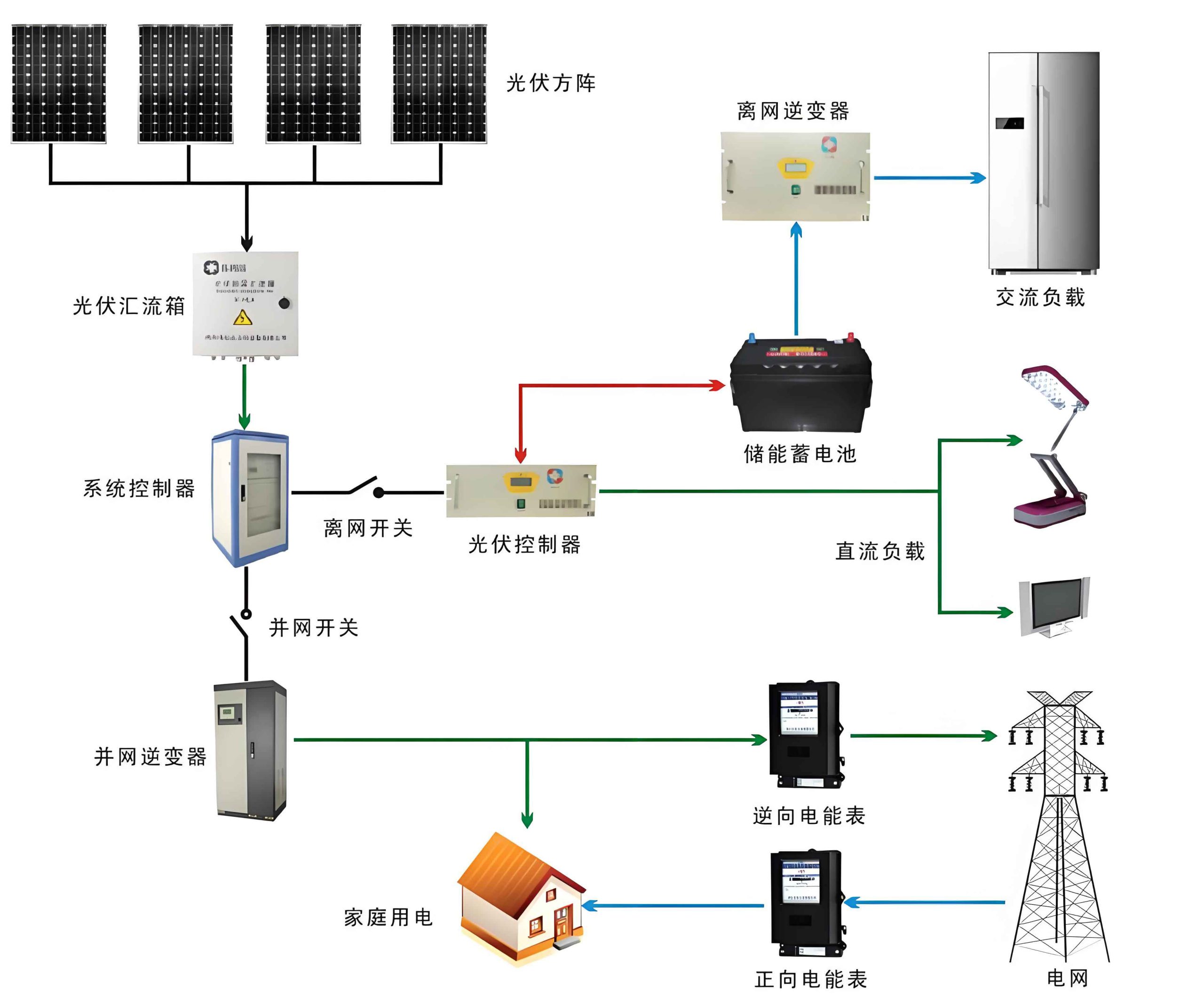
Inverter selection is another critical aspect of the solar system. I opted for string inverters due to their scalability and fault tolerance. The efficiency of an inverter, \(\eta_{\text{inv}}\), affects overall system yield and is given by:
$$\eta_{\text{inv}} = \frac{P_{\text{AC}}}{P_{\text{DC}}} \times 100\%$$
where \(P_{\text{AC}}\) is the AC output power and \(P_{\text{DC}}\) is the DC input power from the PV array. Modern inverters achieve efficiencies above 98%, minimizing energy losses. For this solar system, with multiple inverters rated at 60 kW and 100 kW, I ensured they operate within 80-100% of their capacity to maximize efficiency. The inverters also include maximum power point tracking (MPPT) algorithms that optimize the voltage-current curve, expressed as:
$$P_{\text{max}} = V_{\text{mp}} \times I_{\text{mp}}$$
where \(P_{\text{max}}\) is the peak power output from the solar system under given irradiance conditions. By continuously adjusting the operating point, MPPT can increase energy harvest by up to 20% compared to fixed-voltage systems, highlighting the sophistication embedded in this solar system.
Lightning protection and grounding are vital for the longevity and safety of the solar system. I designed the PV panel frames to serve as lightning receptors, interconnected and grounded to dissipate surges. The grounding resistance \(R_g\) must satisfy:
$$R_g \leq 4 \, \Omega$$
achieved through a grid of copper electrodes buried in the soil. This prevents potential differences that could damage electronic components. Moreover, the solar system includes surge protective devices (SPDs) at combiner boxes and inverters, rated for impulse currents up to 20 kA. The coordination of these protections ensures that the solar system remains operational even during thunderstorms, a common concern in coastal regions.
The economic and environmental benefits of such a solar system are substantial. Over its lifetime, the carport is projected to generate approximately 300,000 kWh annually, offsetting 250 tons of CO₂ emissions per year based on local grid carbon intensity. The payback period can be estimated using the formula:
$$T_{\text{payback}} = \frac{C_{\text{initial}}}{S \times E_{\text{annual}}}$$
where \(C_{\text{initial}}\) is the initial investment cost, \(S\) is the savings per kWh (including feed-in tariffs and reduced charging costs), and \(E_{\text{annual}}\) is the annual energy production. With declining PV costs and supportive policies, \(T_{\text{payback}}\) often falls below 8 years, making the solar system financially attractive. Additionally, the dual-use of land for parking and power generation enhances space efficiency, a key advantage in urban settings.
In terms of maintenance, the solar system requires minimal intervention. Regular inspections involve checking for soiling on panels, loose connections, and vegetation encroachment. The performance ratio (PR) is a useful metric to monitor:
$$\text{PR} = \frac{E_{\text{actual}}}{E_{\text{theoretical}}} \times 100\%$$
where \(E_{\text{actual}}\) is the measured energy output and \(E_{\text{theoretical}}\) is the expected output based on irradiance and panel ratings. A PR above 80% indicates healthy operation. I recommend semi-annual cleaning and annual electrical tests to sustain high PR values, ensuring the solar system delivers consistent returns.
Looking ahead, advancements in solar system technology promise even greater integration. Bifacial PV panels, which capture light from both sides, could boost yields by 10-20% when mounted on reflective surfaces like white pavements. Smart inverters with grid-support functions, such as voltage regulation and frequency response, will enable solar systems to stabilize local grids. Furthermore, incorporating energy storage batteries would allow time-shifting of solar power, addressing intermittency and providing backup during outages. These innovations will transform photovoltaic carports into intelligent energy hubs, reinforcing the role of solar systems in the renewable transition.
In conclusion, the integration of a solar system into parking infrastructure represents a pragmatic step toward sustainable development. Through careful design of structural and electrical components, we can create systems that are not only functional but also resilient and efficient. The solar system discussed here exemplifies how engineering principles—from load calculations to circuit optimization—can be applied to real-world challenges. As solar technology continues to evolve, I am confident that such integrated solutions will become commonplace, contributing to a cleaner, more energy-secure future. By embracing the solar system paradigm, we can turn everyday spaces into power generators, making renewable energy an inseparable part of our built environment.