
When I consider the term “solar system,” my mind journeys through two interconnected realms. The first is the grand cosmic architecture—our planetary system centered on the Sun, a magnificent fusion reactor suspended in the void. The second is the human-engineered counterpart: the photovoltaic (PV) solar system, our method of capturing a minuscule yet vital fraction of that stellar output. This article explores the profound journey of energy from its cosmic origin to its practical application on Earth, delving into the science, technology, and engineering that make it possible. The core of any terrestrial solar system is the panel, the direct interface with sunlight.
The energy that powers our planet originates from the Sun, the heart of our celestial solar system. The power radiated by the Sun can be described by the Stefan-Boltzmann law for a black body:
$$ P_{\text{sun}} = 4 \pi R_{\text{sun}}^2 \sigma T_{\text{sun}}^4 $$
where $R_{\text{sun}}$ is the solar radius, $T_{\text{sun}}$ is the effective surface temperature (~5778 K), and $\sigma$ is the Stefan-Boltzmann constant ($5.67 \times 10^{-8} \, \text{W m}^{-2} \text{K}^{-4}$). Only a tiny fraction of this colossal power, given by the solar constant (approximately 1361 W/m² at Earth’s orbit), reaches our planet. A terrestrial solar system is designed to intercept and convert this flux.
The fundamental conversion principle is the photovoltaic effect. When photons with energy greater than the bandgap energy $E_g$ of a semiconductor material strike it, they can excite electrons from the valence band to the conduction band, creating electron-hole pairs. This generates a voltage and, in a closed circuit, a direct current. The maximum theoretical efficiency for a single-junction solar cell is given by the Shockley-Queisser limit:
$$ \eta_{\text{max}} = \frac{\int_{E_g}^{\infty} \frac{E}{E_{\text{ph}}} I_s(E) \, dE}{\int_{0}^{\infty} I_s(E) \, dE} $$
where $I_s(E)$ is the spectral photon flux from the Sun. This limit peaks around 33.7% for a material with a bandgap of ~1.34 eV under unconcentrated sunlight.
Generations of Photovoltaic Technology
Photovoltaic panels, the building blocks of any solar system, have evolved through distinct generations, each with its own material science and efficiency characteristics.
| Generation | Key Technologies | Typical Lab Efficiency | Commercial Module Efficiency | Key Advantages | Major Challenges |
|---|---|---|---|---|---|
| First | Monocrystalline Silicon (c-Si), Polycrystalline Silicon (mc-Si) | ~26.7% (c-Si) | 20-23% | High efficiency, long-term stability, abundant material | High material & energy cost for purification, rigid & heavy |
| Second | Thin-Film: Amorphous Silicon (a-Si), Cadmium Telluride (CdTe), Copper Indium Gallium Selenide (CIGS) | ~23.4% (CIGS) | 12-19% | Lower material use, flexible substrates, better performance in low-light | Lower efficiency than c-Si, use of rare/toxic materials (Cd, In) |
| Third (Emerging) | Perovskite, Organic PV (OPV), Dye-Sensitized (DSSC), Quantum Dot, Multi-junction Concentrator (CPV) | >29% (Perovskite-Si tandem) | 5-18% (emerging comm.) | Ultra-low-cost potential, tunable bandgaps, lightweight, flexible | Stability issues (esp. perovskite), low long-term field data, scalability |
My analysis of a commercial solar system must consider this technological landscape. The choice between generations involves a trade-off between efficiency, cost, durability, and application. The energy yield of a panel is not just its peak efficiency but its performance over time and under real-world conditions, encapsulated by the performance ratio (PR):
$$ PR = \frac{Y_f}{Y_r} = \frac{\text{Actual AC Energy Output}}{\text{Theoretical DC Nameplate Output}} $$
where $Y_f$ is the final yield and $Y_r$ is the reference yield. Factors like temperature coefficients, spectral response, and low-light behavior are critical. For silicon, power output decreases with temperature, governed by a temperature coefficient $\gamma$ (typically -0.3 to -0.5 %/°C):
$$ P(T) = P_{\text{STC}} \times [1 + \gamma (T – T_{\text{STC}})] $$
where $P_{\text{STC}}$ is power at Standard Test Conditions (25°C).
System Design and Balance of Components
Designing an efficient solar system goes far beyond selecting panels. It is an integrated engineering challenge involving electrical design, structural mechanics, and site optimization. The core electrical equation for a PV string is based on the diode equation for a solar cell, scaled up:
$$ I = I_{\text{ph}} – I_0 \left[ \exp\left(\frac{q(V + I R_s)}{n k T}\right) – 1 \right] – \frac{V + I R_s}{R_{sh}} $$
where $I_{\text{ph}}$ is the photocurrent, $I_0$ is the saturation current, $R_s$ is series resistance, $R_{sh}$ is shunt resistance, $n$ is the ideality factor, $q$ is electron charge, $k$ is Boltzmann’s constant, and $T$ is cell temperature. Mismatch between panels, partial shading, and inverter characteristics dramatically affect the overall solar system output.
The structural design is equally paramount, especially on challenging terrain. As referenced in earlier discussions on slope mounting, the choice of support structure is critical for safety, cost, and longevity. The design must account for permanent loads (dead weight), variable loads (wind, snow), and special loads (seismic). The fundamental requirement is that the allowable stress $\sigma_{\text{all}}$ is not exceeded by the design stress $\sigma_{\text{des}}$:
$$ \sigma_{\text{des}} = \frac{M}{S} + \frac{N}{A} \leq \sigma_{\text{all}} = \frac{F_y}{\gamma_m} $$
where $M$ is bending moment, $S$ is section modulus, $N$ is axial force, $A$ is cross-sectional area, $F_y$ is yield strength, and $\gamma_m$ is a material safety factor. Wind load is often dominant, calculated using codes like ASCE 7 or Eurocode 1:
$$ F_w = q_p(z) \cdot C_f \cdot A_{\text{ref}} $$
$$ q_p(z) = 0.5 \cdot \rho \cdot v_b^2 \cdot C_e(z) \cdot C_t $$
where $q_p$ is peak velocity pressure, $C_f$ is force coefficient, $v_b$ is basic wind speed, and $C_e$, $C_t$ are exposure and topography factors.
For large-scale solar system deployment, especially on sloped or uneven land, innovative mounting solutions are key. Let’s analyze three primary structural solutions, expanding on the comparative framework:
| Aspect | Simple Steel Support System | Truss Frame Support System | Flexible (Cable-Supported) System |
|---|---|---|---|
| Structural Concept | Series of individual steel frames fixed to foundations, supporting rails for panels. | Continuous, lightweight triangulated truss structure spanning between supports, offering high rigidity. | Pre-stressed cables or meshes suspended between anchor points, with panels attached, allowing large spans. |
| Material Usage (t/MW) | ~84 | ~94 | ~65 |
| Foundation Complexity | High. Requires multiple foundations on slope, with challenging access and leveling. | Moderate. Fewer support points needed due to truss span, reducing foundation count on slope. | Low. Primarily requires heavy anchor foundations at perimeter, minimizing work on the slope itself. |
| Key Design Formulas | Beam bending formulas for purlins and posts. $ \delta_{\text{max}} = \frac{5 w L^4}{384 E I} $ for distributed load. | Truss analysis using method of joints/sections. Member force: $ F = \frac{M \cdot d}{I} $ in bending-dominated cases. | Catenary or deflection theory. Sag-tension relationship: $ T = \frac{w L^2}{8 d} $ (approx. for parabolic sag). |
| Primary Advantage | Familiar technology, simple fabrication, no specialized installation crews required. | High stiffness, good for high wind/snow loads, clean underside for vegetation or access. | Lowest material use, minimal slope disturbance, adaptable to very large spans and complex topography. |
| Primary Disadvantage | Highest on-slope construction effort, potentially higher total cost, many potential corrosion points. | Higher fabrication precision required, complex connections, transportation of large truss sections. | Dynamic response to wind (flutter), long-term creep and relaxation of cables, requires specialized design & installation. |
| System Cost (Modeled) | ~1.344 USD/W | ~1.379 USD/W | ~1.220 USD/W |
This detailed comparison shows that for a large-scale solar system on difficult terrain, the flexible support system offers compelling advantages in material efficiency and minimal ground impact, though it introduces unique engineering challenges related to dynamics and long-term material behavior. The optimal choice is a function of specific site constraints, local costs, and developer expertise.
The Invisible Grid: Power Electronics and Integration
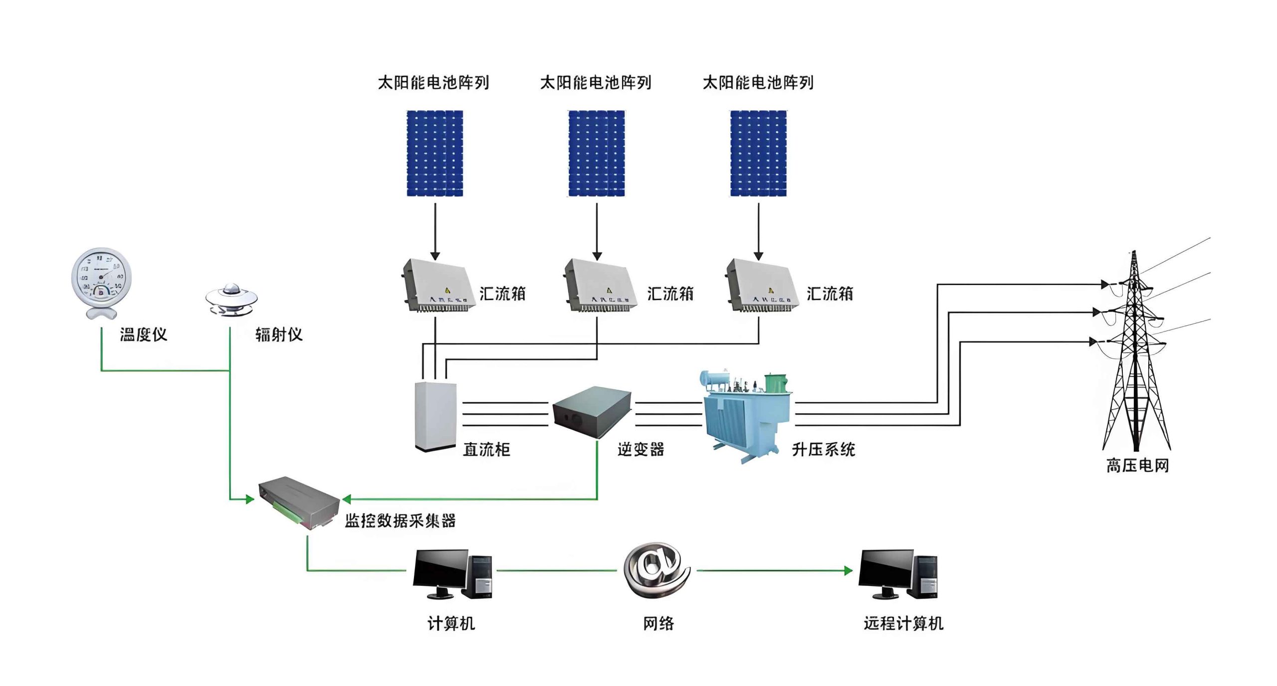
No modern solar system is complete without its “brain” and “nervous system”: the power conversion and management units. Inverters transform the DC output from the panels into grid-compatible AC. Their efficiency $\eta_{\text{inv}}$ is crucial and is often a function of load, described by a European efficiency formula:
$$ \eta_{\text{Euro}} = 0.03 \eta_{5\%} + 0.06 \eta_{10\%} + 0.13 \eta_{20\%} + 0.10 \eta_{30\%} + 0.48 \eta_{50\%} + 0.20 \eta_{100\%} $$
where the subscripts indicate percentage of rated power.
Furthermore, with the rise of bifacial panels, which capture light from both sides, energy modeling becomes more complex. The total irradiance $G_{\text{bifacial}}$ on a bifacial module includes front-side $G_{\text{front}}$ and rear-side $G_{\text{rear}}$ contributions:
$$ G_{\text{bifacial}} = G_{\text{front}} + B \cdot G_{\text{rear}} $$
where $B$ is the bifaciality factor (ratio of rear to front efficiency). $G_{\text{rear}}$ depends on ground albedo $\alpha$, module height, and array spacing, and can be modeled using view factor analysis.
System-level optimization often involves software that uses these physical models to simulate annual yield. The final annual energy production $E_{\text{annual}}$ of a solar system is the integral of its performance over time:
$$ E_{\text{annual}} = \int_{0}^{8760 \, \text{h}} P_{\text{DC}}(t) \cdot \eta_{\text{inv}}(t) \cdot \eta_{\text{other}}(t) \, dt $$
where $P_{\text{DC}}(t)$ is the time-dependent DC power from the array (a function of irradiance, spectrum, and temperature), and $\eta_{\text{other}}$ includes losses from wiring, soiling, and degradation.
Future Vectors: Towards a Higher-Performance Solar System
The evolution of the photovoltaic solar system is accelerating. Tandem cells, which stack materials with different bandgaps to capture a broader spectrum, are pushing efficiencies toward and beyond 30%. The theoretical limit for a two-junction tandem cell is approximately 45% under unconcentrated light, given by:
$$ \eta_{\text{tandem}} = \frac{\int_{E_{g2}}^{\infty} I_s(E) \, dE + \int_{E_{g1}}^{E_{g2}} I_s(E) \, dE}{\int_{0}^{\infty} I_s(E) \, dE} \quad \text{(idealized)} $$
where $E_{g1}$ and $E_{g2}$ are the bandgaps of the top and bottom cells, with $E_{g1} > E_{g2}$.
Integration is another frontier. Building-Integrated Photovoltaics (BIPV), agrivoltaics (combining agriculture with PV), and floating PV are expanding the physical and economic niches for solar system deployment. Each application requires re-thinking the structural, thermal, and optical design of the system. Furthermore, the role of a solar system is shifting from a simple generator to a grid-forming asset, requiring advanced inverters with grid-support functions (voltage regulation, frequency response, black-start capability).
In conclusion, from the nuclear furnace of our celestial solar system to the sophisticated semiconductor devices and steel structures on Earth, the journey of solar energy is a testament to human ingenuity. Designing and deploying an efficient, reliable, and cost-effective terrestrial solar system is a multidisciplinary feat. It requires a deep understanding of semiconductor physics, structural mechanics, electrical engineering, and environmental science. As technology advances, pushing efficiencies higher and costs lower, the solar system—both as a cosmic concept and a human technology—will undoubtedly remain central to our sustainable energy future. The continuous feedback loop between fundamental research, engineering innovation, and field deployment is what propels this vital industry forward, ensuring that we harness more of the immense power our home star provides.