
In the face of rapid global economic growth, traditional energy sources such as coal and natural gas are not only finite but also pose significant environmental challenges. Therefore, there is an urgent need to explore clean and renewable energy alternatives to ensure sustainable power supply. Solar energy, due to its widespread availability and non-polluting nature during conversion to electricity, has seen rapid development in photovoltaic (PV) technology. However, a major limitation of PV cells is their inability to fully absorb incident photon energy, leading to heat accumulation within the cell. This heat buildup elevates operating temperatures, reducing efficiency and lifespan, particularly in regions with high solar irradiance. For instance, in northern summers, temperature differences between PV cells and the environment can exceed 36°C, causing issues like yellowing or cracking. To address this, thermoelectric (TE) generation, based on the Seebeck effect, offers a promising solution by converting waste heat into electricity, utilizing infrared radiation in the 800nm to 3000nm range.
Conventional integrated PV-TE systems often couple PV cells directly with TE modules, but this approach yields limited power enhancement—typically only 2% to 4% higher than standalone PV systems. Moreover, such systems require expensive materials like gallium arsenide concentrator cells, which cost hundreds of times more than polycrystalline silicon cells, hindering economic viability and large-scale adoption. In this study, I propose a novel integrated system that separates concentrated PV and TE generation into parallel processes. This design not only boosts overall power output but also enhances PV cell safety by reducing thermal stress. Through experimental validation, I demonstrate that this solar system achieves a 5% to 16% increase in total output power and approximately 3% improvement in efficiency compared to standalone PV systems, maximizing renewable energy utilization.
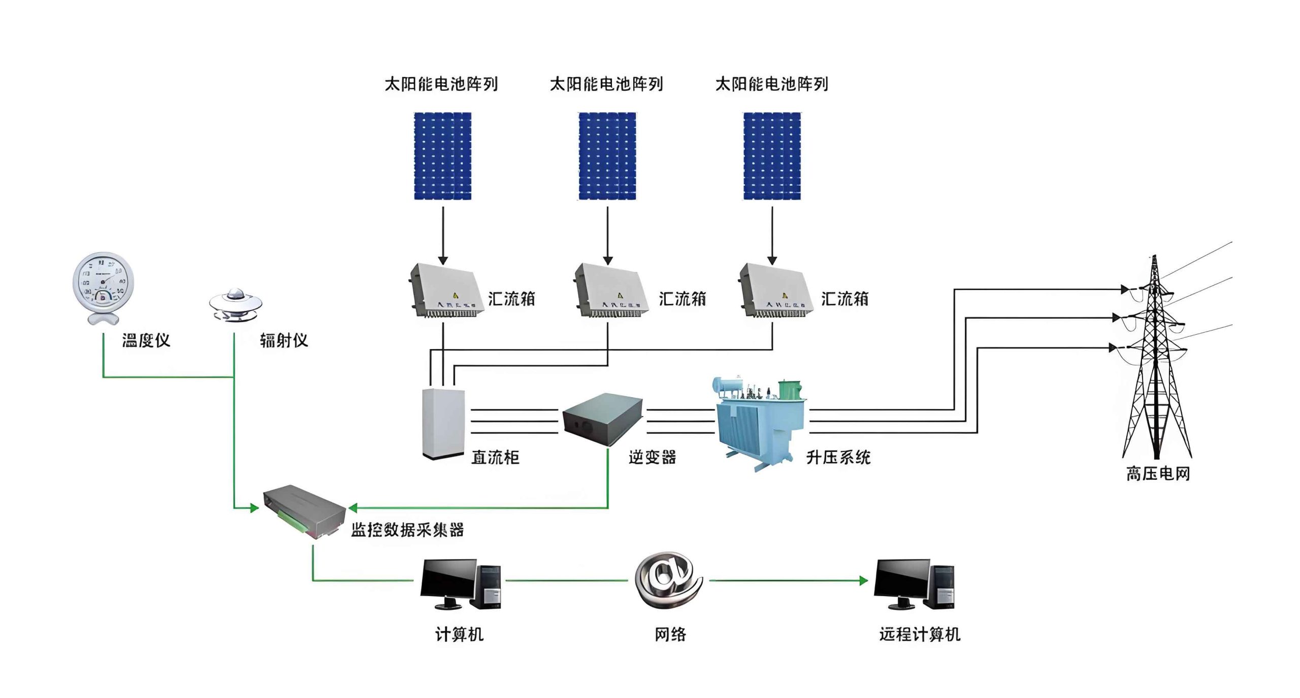
The core innovation lies in the parallel processing of concentrated PV and TE systems. Instead of direct coupling, the PV cell is positioned near the concentrator to receive focused sunlight, while a heat-absorbing medium is placed at the focal point to drive multi-stage TE modules. This configuration allows independent optimization of each component, improving both performance and cost-effectiveness. The solar system incorporates a Fresnel lens for concentration, polycrystalline silicon PV cells for affordability, and a multi-stage TE generator with active water cooling. Experiments were conducted in an open environment over a full day, with data collected hourly to assess performance under varying solar irradiance. Results confirm the feasibility of this integrated approach, highlighting its potential for advancing renewable energy technologies.
To understand the underlying mechanisms, let’s delve into the principles of PV and TE generation. The photovoltaic effect, discovered by Edmond Becquerel in 1839, involves the generation of an electric current when light strikes a material, typically a semiconductor p-n junction. Under illumination, photons with energy greater than the bandgap excite electrons from the valence band to the conduction band, creating electron-hole pairs. These carriers are separated by the built-in electric field at the junction, producing a photocurrent. The output power of a PV cell can be expressed as:
$$P_{pv} = I_{ph} \times V_{oc} \times FF$$
where \(I_{ph}\) is the photocurrent, \(V_{oc}\) is the open-circuit voltage, and \(FF\) is the fill factor. The efficiency \(\eta_{pv}\) is given by:
$$\eta_{pv} = \frac{P_{pv}}{A \times G} \times 100\%$$
Here, \(A\) is the cell area and \(G\) is the solar irradiance. For polycrystalline silicon cells used in this solar system, typical efficiencies range from 14% to 19%, as observed in experiments.
Thermoelectric generation relies on the Seebeck effect, where a temperature gradient across two dissimilar conductors or semiconductors induces a voltage. In a TE module, p-type and n-type materials are connected electrically in series and thermally in parallel. When heat is applied to one side, charge carriers diffuse from the hot to cold end, generating an electromotive force. The voltage \(V_{te}\) produced is proportional to the temperature difference \(\Delta T\):
$$V_{te} = \alpha \times \Delta T$$
where \(\alpha\) is the Seebeck coefficient. The output power of a TE module depends on the internal resistance and load matching. For a multi-stage TE generator, as implemented in this solar system, each stage operates independently, with heat cascading from the top to bottom stages. This design enhances overall stability and power output, as even if one stage fails, others continue functioning. The total TE power \(P_{te}\) is the sum of individual stage powers:
$$P_{te} = \sum_{i=1}^{n} P_{te,i}$$
where \(n\) is the number of stages. In this study, a three-stage TE generator was used, with each stage contributing incrementally to the total output.
The hardware design of the integrated solar system comprises two main parts: the solar concentration unit and the composite generation module. A Fresnel lens serves as the concentrator due to its thin profile, high transmittance, lightweight, and low cost. It focuses sunlight onto both the PV cell and the heat-absorbing medium, increasing energy density. The PV cell is a standard polycrystalline silicon type, chosen for its affordability and reliability, positioned slightly away from the focal point to avoid overheating. The TE module consists of multiple TE chips stacked to form a multi-stage generator. Each stage is thermally connected via high-conductivity insulating materials, with the hot side of one stage attached to the cold side of the next. Active cooling is provided by a water circulation system, including copper pipes, a pump, and coolant, to maintain a low temperature at the cold end and enhance the temperature gradient.
The experimental platform was set up in an unobstructed outdoor area. The Fresnel lens was manually adjusted to track the sun, ensuring optimal focus throughout the day. Data were recorded hourly from morning to evening, with load resistors varied to measure maximum power points. The solar system’s structure is illustrated in the diagram below, showing the parallel arrangement of PV and TE components. This design allows the PV cell to operate at lower temperatures while the TE module utilizes concentrated heat, improving overall efficiency.
Results from the experiments are summarized in the following tables and analysis. The maximum output power of each component was measured at different times, revealing trends aligned with solar irradiance. Table 1 shows the power outputs for the PV cell and each TE stage over a typical day.
| Time of Day | PV Power, \(P_{pv}\) (W) | TE Stage 1 Power, \(P_{te1}\) (W) | TE Stage 2 Power, \(P_{te2}\) (W) | TE Stage 3 Power, \(P_{te3}\) (W) | Total Power, \(P_{total}\) (W) |
|---|---|---|---|---|---|
| 8:00 | 0.48 | 0.027 | 0.008 | 0.001 | 0.516 |
| 9:00 | 0.65 | 0.045 | 0.012 | 0.002 | 0.709 |
| 10:00 | 0.82 | 0.067 | 0.018 | 0.003 | 0.908 |
| 11:00 | 1.05 | 0.089 | 0.028 | 0.005 | 1.172 |
| 12:00 | 1.20 | 0.101 | 0.036 | 0.006 | 1.343 |
| 13:00 | 1.15 | 0.095 | 0.032 | 0.005 | 1.282 |
| 14:00 | 1.10 | 0.082 | 0.025 | 0.004 | 1.211 |
| 15:00 | 0.95 | 0.070 | 0.020 | 0.003 | 1.043 |
| 16:00 | 0.78 | 0.052 | 0.015 | 0.002 | 0.849 |
| 17:00 | 0.60 | 0.035 | 0.010 | 0.001 | 0.646 |
| 18:00 | 0.50 | 0.025 | 0.008 | 0.001 | 0.534 |
As observed, \(P_{pv}\) peaks at noon with 1.20 W, while TE powers are lower but follow a similar trend. The total power \(P_{total}\) is the sum of PV and all TE stages. Compared to standalone PV, the integrated solar system shows a power enhancement ranging from 5% to 16%, calculated as:
$$\text{Power Enhancement} = \left( \frac{P_{total} – P_{pv}}{P_{pv}} \right) \times 100\%$$
For example, at 12:00, the enhancement is \(\left( \frac{1.343 – 1.20}{1.20} \right) \times 100\% \approx 11.9\%\). This demonstrates the synergistic effect of combining PV and TE generation in this solar system.
The electrical conversion efficiency is another critical metric. Table 2 presents the efficiencies of the PV cell, TE stages, and the overall system at different times. The PV efficiency \(\eta_{pv}\) is computed using the formula above, with irradiance data measured during experiments. The TE efficiency \(\eta_{te}\) for each stage is derived from the power output relative to the heat input, though for simplicity, we focus on the overall system efficiency \(\eta_{system}\).
| Time of Day | PV Efficiency, \(\eta_{pv}\) (%) | TE Efficiency, \(\eta_{te}\) (%) | System Efficiency, \(\eta_{system}\) (%) |
|---|---|---|---|
| 8:00 | 14.2 | 2.1 | 16.5 |
| 9:00 | 15.8 | 3.5 | 18.3 |
| 10:00 | 16.5 | 4.8 | 19.8 |
| 11:00 | 17.9 | 5.9 | 21.2 |
| 12:00 | 18.9 | 6.7 | 21.6 |
| 13:00 | 18.5 | 6.2 | 20.9 |
| 14:00 | 17.8 | 5.5 | 20.1 |
| 15:00 | 16.3 | 4.8 | 18.7 |
| 16:00 | 15.1 | 3.9 | 17.5 |
| 17:00 | 14.5 | 2.8 | 16.4 |
| 18:00 | 14.0 | 2.0 | 16.1 |
The system efficiency \(\eta_{system}\) is calculated as the total output power divided by the solar input power. It ranges from 16.1% to 21.6%, which is about 2% to 3% higher than standalone PV efficiency. This improvement, though modest, highlights the benefit of integrating TE generation to utilize waste heat. The solar system’s performance is consistently better across the day, validating the design’s effectiveness.
To further analyze the solar system’s behavior, we can model the power output as a function of temperature and irradiance. For the PV cell, the temperature coefficient affects efficiency, often described by:
$$\eta_{pv}(T) = \eta_{ref} \left[ 1 – \beta (T – T_{ref}) \right]$$
where \(\eta_{ref}\) is the efficiency at reference temperature \(T_{ref}\), and \(\beta\) is the temperature coefficient. In this solar system, the parallel design helps keep PV temperatures lower, mitigating efficiency loss. For the TE module, the power output depends on the temperature gradient, which can be expressed as:
$$P_{te} = \frac{\alpha^2 \Delta T^2}{4R}$$
assuming matched load, where \(R\) is the internal resistance. The multi-stage configuration amplifies this by creating larger effective \(\Delta T\) across stages.
In conclusion, this integrated concentrated photovoltaic and multi-stage thermoelectric generation system demonstrates a practical approach to enhancing solar energy conversion. By parallel processing of PV and TE components, the solar system achieves higher output power and efficiency while protecting PV cells from thermal degradation. Experimental results confirm a 5% to 16% power boost and around 3% efficiency gain compared to standalone PV, making it a promising solution for renewable energy applications. However, limitations exist, such as the need for automated solar tracking and improved portability. Future work could focus on optimizing the solar system’s design with advanced materials and control strategies to further increase performance. This research contributes to the advancement of hybrid solar systems, paving the way for more efficient and sustainable energy harvesting.
The success of this solar system underscores the importance of interdisciplinary approaches in renewable energy. By leveraging both photovoltaic and thermoelectric effects, we can maximize the utilization of solar radiation, addressing both electrical and thermal energy needs. As global energy demands rise, such integrated systems will play a crucial role in transitioning to a cleaner future. I envision that continued innovation in this solar system technology will lead to broader adoption, especially in off-grid and remote areas where energy reliability is critical. Ultimately, the goal is to create a robust and cost-effective solar system that harnesses the sun’s full potential, contributing to energy security and environmental preservation.