
The pursuit of higher energy density and absolute safety in energy storage has propelled the development of all-solid-state batteries (ASSBs). Among the various solid electrolyte candidates, sulfide-based materials have emerged as the most promising due to their exceptional ionic conductivity, which can surpass that of liquid electrolytes, and their favorable mechanical properties enabling good processability. A sulfide-based solid-state battery represents a paradigm shift, replacing flammable organic liquid electrolytes with a solid, inorganic ion conductor. This transition promises to eliminate combustion risks and enable the use of high-capacity electrodes like lithium metal, potentially doubling energy density. However, the shift from a dynamic liquid-solid interface to a static solid-solid interface introduces profound challenges. The performance and longevity of a sulfide-based solid-state battery are critically governed by the stability, intimacy, and transport kinetics at these internal interfaces.
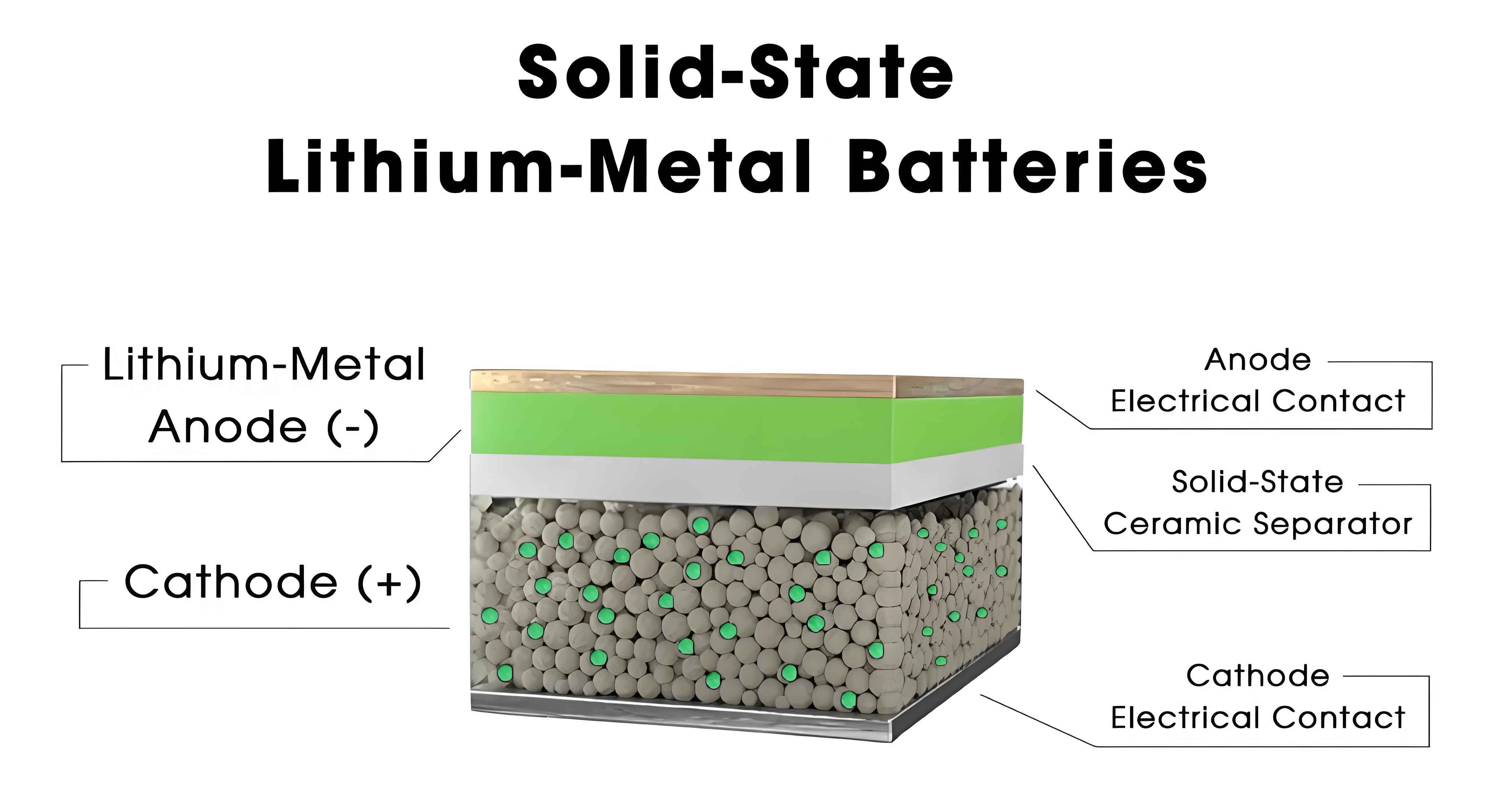
The core of a sulfide-based solid-state battery consists of three main components: a composite cathode (active material, solid electrolyte, conductive additive), a dense sulfide solid electrolyte separator layer, and an anode (lithium metal, alloy, or graphite composite). Each junction between these layers harbors specific interfacial instabilities that can lead to high impedance, capacity fade, and catastrophic failure. This article delves into the fundamental causes of these interfacial issues and systematically reviews the latest strategies to engineer stable, low-resistance interfaces, which is the key to unlocking the commercial potential of the sulfide-based solid-state battery.
Fundamental Challenges at Solid-Solid Interfaces
Unlike liquid electrolytes which can wet and conform to electrode surfaces, solid electrolytes form rigid, point-contact interfaces. This fundamental difference leads to several intrinsic problems in a solid-state battery:
- Poor Physical Contact & Void Formation: Mechanical stress from volume changes during cycling can break contacts and create gaps, drastically increasing interfacial resistance.
- Chemical & Electrochemical Instability: Sulfide electrolytes can be reduced by low-potential anodes (e.g., Li metal) or oxidized by high-voltage cathodes, forming resistive decomposition products.
- Space-Charge Layer Effects: A difference in Li+ chemical potential between the electrode and electrolyte can cause ion depletion/enrichment at the interface, creating a high-impedance zone.
- Dendrite Propagation: Lithium filaments can grow along grain boundaries or through cracks in the solid electrolyte, causing short circuits.
The severity of these issues varies depending on the electrode material. Therefore, the interfacial design for a high-performance sulfide-based solid-state battery must be approached from both the anode and cathode sides.
Anode/Sulfide Electrolyte Interfaces
The Lithium Metal Challenge
Lithium metal is the ultimate anode for a solid-state battery due to its high theoretical capacity (3860 mAh g-1) and low electrochemical potential (-3.04 V vs. SHE). However, its interface with sulfide electrolytes is notoriously unstable.
1. Instability and High Interfacial Resistance: Most sulfide electrolytes (e.g., Li10GeP2S12 (LGPS), Li6PS5Cl (LPSCl)) are thermodynamically unstable against Li metal. Upon contact, they are reduced, forming a passivating solid electrolyte interphase (SEI). This SEI is often a complex mixture of Li3P, Li2S, Li-Ge alloys, and other reduced species. Unlike in liquid systems, this SEI is brittle and cannot self-heal, leading to continuously growing impedance. The reaction can be generalized as:
$$\text{Sulfide Electrolyte} + x\text{Li}^+ + x\text{e}^- \rightarrow \text{Li}_2\text{S} + \text{Li}_3\text{P} + \text{Li-M Alloys} + \ldots$$
This irreversible consumption of both lithium and electrolyte cripples the cycle life of the lithium-metal solid-state battery.
2. Dendrite Growth and Short Circuit: The local current density at imperfections on the Li metal surface can be extremely high, leading to non-uniform Li plating. Lithium dendrites can penetrate the sulfide electrolyte along grain boundaries or through micro-cracks, ultimately causing an internal short circuit. The critical current density (CCD) before dendrite-induced failure is a key metric for a practical solid-state battery.
| Strategy | Approach | Mechanism & Benefit | Example Materials/Techniques |
|---|---|---|---|
| Anode Modification | Use of Lithium Alloys | Raises the anode potential, reducing the thermodynamic driving force for electrolyte reduction. | Li-In, Li-Al, Li-Si. Li-In (~0.62 V vs. Li/Li+) is most common. |
| Electrolyte Modification | Doping/Composition Tuning | Enhances intrinsic stability or forms a more stable SEI in situ. | P2O5 doping in Li3PS4; Using more stable halogen-rich phases (e.g., LPSCl). |
| Artificial Interphase (AIL) | Inserting a Protective Layer | Physically separates Li from the sulfide, providing a stable, Li+-conductive barrier. | In-situ formed LixSiSy; Sputtered Li3PO4; LiF, Li3N layers. |
| Mechanical Constriction | Using Composite Anodes under Pressure | Improves physical contact, homogenizes Li+ flux, and suppresses void formation. | Li/C composite anodes; Stack pressure during cell operation. |
| Hybrid Layer Design | Organic-Inorganic Composite Coating | Combines the flexibility of polymers with the stability of inorganic phases to guide uniform Li deposition. | LiCl-organic composite layers formed by chemical reaction. |
The effectiveness of an artificial interphase can be quantified by the stabilization of the interfacial resistance ($R_{int}$) over time. A successful strategy should minimize the growth rate $dR_{int}/dt$. For composite anodes, the effective ionic conductivity ($\sigma_{eff, composite}$) is crucial and can be estimated using effective medium theory, often following the Bruggeman relation for a mixture of ionic conductor (electrolyte, $\sigma_e$) and electronic conductor (graphite/C, $\sigma_c$):
$$\sigma_{eff, composite} = \sigma_e \cdot \phi_e^{1.5}$$
where $\phi_e$ is the volume fraction of the solid electrolyte in the composite.
Graphite and Composite Anodes
Graphite is attractive due to its maturity and low volume expansion. In a sulfide-based solid-state battery, the graphite anode is a composite of graphite particles, sulfide electrolyte powder, and sometimes a conductive additive. The interfacial challenge here is primarily morphological.
The performance is highly sensitive to the composite’s microstructure. Insufficient solid electrolyte leads to poor ionic percolation, while too much graphite reduces the ionic transport paths. An optimal volume ratio is essential. Furthermore, the particle size distribution (PSD) of both graphite and sulfide electrolyte significantly impacts the packing density and contact area. A bimodal PSD, where smaller electrolyte particles fill the voids between larger ones, can maximize the contact area and ionic conductivity within the composite electrode, directly enhancing the rate capability of the solid-state battery. The capacity retention ($CR$) over cycles is a strong function of this microstructure stability.
Cathode/Sulfide Electrolyte Interfaces
The cathode interface in a sulfide-based solid-state battery is arguably more complex due to the presence of two distinct yet interconnected interfaces: 1) between the cathode active material (CAM) particles and the sulfide electrolyte within the composite cathode, and 2) between the bulk composite cathode layer and the dense separator electrolyte layer.
CAM/Sulfide Electrolyte Interface
High-voltage layered oxide CAMs (e.g., NCM, NCA, LCO) are chemically incompatible with sulfide electrolytes.
1. Oxidative Decomposition: At high states of charge (e.g., >4.2 V vs. Li/Li+), sulfide electrolytes can be oxidized, producing insulating species like elemental sulfur, polysulfides (Li2Sx), phosphorus sulfides (P2Sx), and phosphates. This degradation layer increases charge transfer resistance and consumes active lithium.
2. Space-Charge Layer Formation: This is a thermodynamic issue arising from the difference in Li+ chemical potential ($\mu_{Li^+}$) between the CAM and the sulfide electrolyte. When in contact, Li+ diffuses from the electrolyte (higher $\mu_{Li^+}$) into the CAM (lower $\mu_{Li^+}$), leaving a Li+-depleted region in the electrolyte near the interface. This region has drastically reduced ionic conductivity, acting as a significant interfacial barrier. The width of the space-charge layer ($\lambda$) is given by the Debye length:
$$\lambda = \sqrt{\frac{\epsilon_r \epsilon_0 k_B T}{2e^2 c_0}}$$
where $\epsilon_r$ is the dielectric constant, $\epsilon_0$ is vacuum permittivity, $k_B$ is Boltzmann’s constant, $T$ is temperature, $e$ is electron charge, and $c_0$ is the bulk Li+ concentration in the electrolyte.
The Primary Solution: Oxide Coatings. Applying a thin, ion-conducting, and electrochemically stable oxide coating on CAM particles is the most effective and widely adopted strategy. The coating acts as a buffer layer that: (i) prevents direct contact and chemical reactions, (ii) mitigates the space-charge effect by providing a gradient in $\mu_{Li^+}$, and (iii) can accommodate volume changes. The effectiveness hinges on the coating’s own ionic conductivity ($\sigma_{coat}$) and thickness ($d_{coat}$). The total interfacial impedance ($Z_{int}$) with a coating can be modeled as a series combination of the coating resistance and the charge transfer resistance at the new interface:
$$Z_{int} \approx \frac{d_{coat}}{\sigma_{coat}} + R_{ct, coat-CAM}$$
Common and successful coating materials include LiNbO3, Li2SiO3, Li2O–ZrO2, and Li3PO4.
Cathode Layer/Electrolyte Separator Interface
This macroscopic interface suffers from poor “wetting” and mechanical decoupling. During cycling, the repeated expansion and contraction of the composite cathode can detach it from the rigid separator layer, creating voids and increasing the cell impedance.
Processing and Binder Engineering: The choice of binder and processing method is critical. “Dry” processes involve simple powder pressing, which may leave weak inter-particle adhesion. “Wet” or slurry processes, where the composite cathode is cast using a solvent and binder, can produce more cohesive and denser layers. The key is finding a binder compatible with sulfide electrolytes (non-polar solvents like xylene or toluene must be used) that provides strong adhesion without compromising ionic transport. Binders like nitrile butadiene rubber (NBR) have shown promise due to polar nitrile groups interacting with sulfide particles. The goal is to maximize the effective contact area $A_{eff}$ at this interface to minimize the area-specific resistance (ASR):
$$ASR = \frac{R_{interface} \cdot A_{geom}}{A_{eff}}$$
where $A_{geom}$ is the geometric area. An ideal process maximizes $A_{eff}/A_{geom}$ close to 1.
| Interface Location | Primary Phenomenon | Consequences | Mitigation Strategies | Key Performance Metrics Impacted |
|---|---|---|---|---|
| Li Metal / SE | Electrochemical Reduction & Dendrite Growth | High $R_{int}$, Li/SE consumption, internal short | AIL, Li alloys, electrolyte doping, mechanical pressure | CCD, Cycle life, Coulombic efficiency |
| Graphite Composite / SE | Poor Ionic Percolation & Contact Loss | Low utilization, poor rate performance, capacity fade | Optimized composite ratio, bimodal PSD, conductive additives | Reversible capacity, Rate capability |
| CAM (NCM, etc.) / SE | Oxidative Decomposition & Space-Charge Layer | High charge transfer $R_{ct}$, capacity fade, voltage hysteresis | Oxide nanocoating (LiNbO3, LZO, etc.) | High-voltage stability, Power density |
| Cathode Layer / SE Separator | Mechanical Delamination & Void Formation | Increasing bulk resistance, current inhomogeneity | Wet-process with functional binders (NBR), isostatic pressing | Area-Specific Resistance (ASR), Long-term cycling stability |
Future Perspectives and Concluding Remarks
The journey towards a commercially viable sulfide-based solid-state battery is fundamentally a journey of interfacial engineering. While significant progress has been made in understanding and mitigating individual interface problems, future research must take a more holistic, cell-level approach. Key frontiers include:
- Multifunctional Interlayers: Developing single layers that simultaneously address chemical instability, space-charge effects, and mechanical stress.
- In-situ and Operando Characterization: Deploying advanced techniques like X-ray tomography, neutron depth profiling, and environmental TEM to observe interface evolution in real-time under operating conditions.
- Scalable Manufacturing: Translating lab-scale coating and processing techniques (e.g., atomic layer deposition for coatings, slot-die casting for electrodes) to cost-effective, high-throughput methods.
- Integrated Modeling: Coupling continuum models of electrochemistry with mesoscale models of microstructure evolution and fracture mechanics to predict long-term performance.
The promise of the sulfide-based solid-state battery—unprecedented safety and energy density—remains compelling. The recent demonstrations of prototype cells achieving energy densities near 900 Wh/L underscore that the technological hurdles are surmountable. The focus has decisively shifted from merely discovering new sulfide electrolytes with high bulk conductivity to the sophisticated design and control of the intricate solid-solid interfaces that ultimately determine the fate of the entire cell. Success in this endeavor will not be marked by a single breakthrough but by the systematic integration of materials science, electrochemistry, and mechanical engineering to create a stable, low-impedance interfacial architecture. This is the critical path for transforming the sulfide-based solid-state battery from a promising concept into a foundational technology for the next generation of electric vehicles and high-performance electronics.