
The relentless pursuit of higher energy density and enhanced safety in electrochemical energy storage has positioned all-solid-state batteries (ASSBs) as a pivotal technology for the next generation of electric vehicles and grid storage. Replacing the flammable liquid electrolyte with a solid-state ion conductor eliminates combustion risks and enables the use of high-capacity lithium metal anodes. Among the various classes of solid-state electrolytes (SSEs)—polymers, oxides, sulfides, and halides—halide-based SSEs have emerged as particularly promising candidates for integration within the composite cathode. Their appeal lies in a compelling combination of properties: high room-temperature ionic conductivity (often exceeding 10–3 S cm–1), excellent oxidative stability against high-voltage cathode materials, good deformability, and relative stability in ambient air compared to their sulfide counterparts. Representative compounds like Li3InCl6 (LIC), Li3YCl6 (LYC), and Li2ZrCl6 (LZC) have demonstrated the potential to unlock high-energy-density solid-state battery configurations.
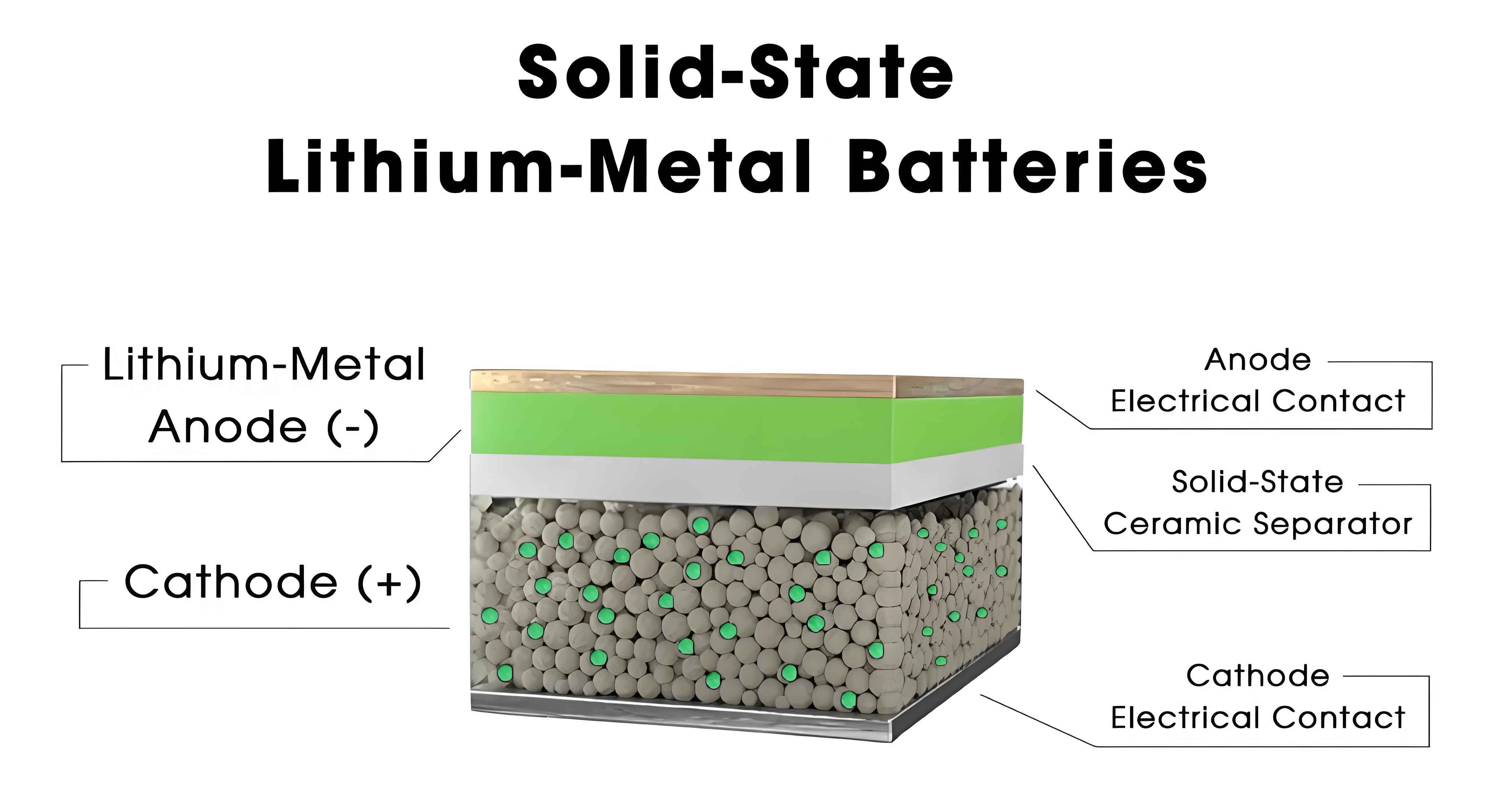
However, the transition from promising material properties to a reliable, high-performance solid-state battery is critically hampered by interfacial instability, especially at the cathode composite. The composite cathode is a multiphase mixture of cathode active material (CAM) particles, SSE particles, and electronic conductive additives. The interfaces between these components, particularly between the CAM and the halide SSE, are sites of complex and often detrimental interactions that govern the overall cell performance. This article, from a researcher’s perspective, delves into the fundamental failure mechanisms at these cathode interfaces and systematically reviews the evolving strategies to mitigate them. It aims to provide a comprehensive framework for understanding and engineering stable interfaces in halide-based ASSBs.
1. Decoding Cathode Interface Failure Mechanisms
The superior performance of a halide-based solid-state battery is contingent on maintaining intimate and stable physical contact as well as facile ionic transport across the CAM-SSE interface throughout cycling. Failure arises from a confluence of mechanical, electrochemical, and chemical degradation pathways.
1.1 Mechanical Contact Degradation
Unlike liquid electrolytes that can infiltrate gaps, solid-solid contact is rigid. State-of-the-art layered oxide cathodes (e.g., LiNixMnyCozO2, NCM) undergo significant anisotropic volume changes during lithium (de)intercalation. This repeated expansion and contraction generates mechanical stress at particle-particle contacts. For polycrystalline secondary CAM particles, this can lead to intra-granular cracking, isolating primary grains and creating “dead zones” inaccessible to Li+ ions. Concurrently, the cyclic volume changes cause CAM and SSE particles to detach from each other, breaking the percolating ionic conduction network. The loss of contact directly increases interfacial impedance and leads to capacity fade. The problem is exacerbated at high current rates and with high active material loadings, where stress accumulation is more rapid.
1.2 The Space Charge Layer (SCL) Effect
When two dissimilar solid ionic conductors with different chemical potentials for Li+ (µLi+) are brought into contact, Li+ diffuses from the phase with higher µLi+ to the one with lower µLi+ to equilibrate the electrochemical potential. In a typical cathode|halide SSE interface, the delithiated cathode has a very high µLi+ during charge. This drives Li+ from the SSE into the cathode, depleting Li+ in a thin region of the SSE adjacent to the interface. This Li+-depleted layer has high resistance because the charge carrier concentration is low. An internal electric field (E) builds up, opposing further Li+ migration.
The potential (φ) and Li+ concentration (c) profile across such an interface can be described by the Poisson-Boltzmann distribution for a planar interface model:
$$
\frac{d^2 \phi}{dx^2} = -\frac{\rho(x)}{\epsilon}
$$
where ρ(x) is the charge density and ε is the permittivity. The width of the SCL (λ) is analogous to the Debye length:
$$
\lambda = \sqrt{\frac{\epsilon k_B T}{2z^2 e^2 c_0}}
$$
where kB is Boltzmann’s constant, T is temperature, z is charge number, e is elementary charge, and c0 is the bulk Li+ concentration. In halide SSEs with high bulk conductivity (high c0), λ is typically small (nanometer scale). However, its impact on interfacial kinetics can be significant, especially if interfacial reactions modify the local composition and effectively increase the resistive layer’s thickness.
1.3 Interfacial (Electro)Chemical Reactions
This is the most pervasive and damaging failure mode. It encompasses two aspects: (i) direct chemical reaction between the CAM and the SSE, and (ii) electrochemical oxidation of the SSE itself at high potentials.
i. Chemical Reactivity: The thermodynamic stability of the CAM|SSE interface can be assessed by calculating the reaction energy (ΔEr) for possible decomposition. For instance, the reaction between LiNi0.8Co0.1Mn0.1O2 and Li3InCl6 may proceed as:
$$
\text{LiNi}_{0.8}\text{Co}_{0.1}\text{Mn}_{0.1}\text{O}_2 + \delta \text{Li}_3\text{InCl}_6 \rightarrow \text{Li}_{1-\delta}\text{Ni}_{0.8}\text{Co}_{0.1}\text{Mn}_{0.1}\text{O}_{2-\gamma} + \delta \text{InO}_x + \delta’ \text{LiCl} + \text{other byproducts}
$$
A positive ΔEr indicates instability. Computational screening has shown that halides are generally more stable against oxide cathodes than sulfides, but reactivity increases with Ni-content in NCM and at elevated temperatures or potentials.
ii. Electrochemical Oxidation: The intrinsic electrochemical window of an SSE is governed by its electronic structure. Oxidation occurs when the SSE’s highest occupied molecular orbital (HOMO) energy is higher than the cathode’s Fermi level during charging, leading to electron loss from the SSE. In halides, this often involves oxidation of Cl– ions:
$$
2\text{Cl}^- \rightarrow \text{Cl}_2 + 2e^-
$$
The generated Cl2 or other chlorine species can further react with the CAM or reduce at other interfaces, creating a complex mixture of resistive decomposition products (e.g., LiCl, transition metal chlorides/oxychlorides, oxidized organic carbon). This decomposition layer constitutes the cathode electrolyte interphase (CEI). While a thin, stable CEI can be passivating, its uncontrolled growth consumes active Li+ and dramatically increases charge-transfer resistance, crippling the solid-state battery performance.
| Failure Mechanism | Primary Cause | Consequence | Key Characteristics |
|---|---|---|---|
| Mechanical Contact Loss | CAM volume changes, stack pressure | Increased interfacial impedance, active material isolation | Visible cracks, capacity fade scaling with cycle number |
| Space Charge Layer | Chemical potential mismatch (ΔµLi+) | Increased interfacial resistance, kinetic limitation | Inherent to all solid-solid interfaces, width ~λ |
| Interfacial Reactions | Thermodynamic instability / Electrochemical oxidation | Formation of resistive CEI, active Li loss, gas evolution | Voltage hysteresis, impedance growth, observable via XPS/TEM |
2. Strategic Mitigation: From Materials to Architecture
Addressing the multifaceted interface challenge requires a holistic approach spanning electrolyte design, cathode surface engineering, and composite electrode architecture.
2.1 Halide Solid-State Electrolyte Engineering
The goal is to enhance the intrinsic (electro)chemical resilience of the halide SSE without compromising its ionic conductivity.
2.1.1 Anion and Cion Doping/Substitution: The electrochemical stability is closely tied to the halogen species. The redox activity follows I– > Br– > Cl– > F–. Partial substitution of Cl with F is highly effective. For example, Li3-xZr1-xTaxCl6-yFy compounds show significantly raised oxidation onset potentials (>4.8 V vs. Li/Li+). The stronger M-F bond increases the formation energy of the decomposed state. Similarly, cation doping with high-valent (e.g., Ta5+, Zr4+) or redox-inert (e.g., Yb3+) elements can stabilize the crystal lattice and modify the HOMO level. The ionic conductivity σ as a function of dopant concentration often follows a nonlinear trend, described by:
$$
\sigma = \frac{A}{T} \exp\left(-\frac{E_a}{k_B T}\right)
$$
where A is a pre-exponential factor and Ea is the activation energy. Optimal doping minimizes Ea while maximizing the stability factor A.
2.1.2 High-Entropy Design: Incorporating multiple metal cations into the halide structure (e.g., Li2.2In0.2Sc0.2Zr0.2Hf0.2Ta0.2Cl6) creates configurational entropy that stabilizes the phase. More importantly, local lattice distortion can suppress halogen ion polarization and diffusion, kinetically hindering the oxidation process. This can push the practical oxidative stability beyond 4.4 V, a critical threshold for high-Ni NCM cathodes in a solid-state battery.
2.1.3 Surface Passivation: Since degradation initiates at surfaces, applying an ultrathin, conformal coating can shield the halide SSE. Atomic layer deposition (ALD) of Al2O3 or TiO2 (1-2 nm) has been shown to drastically reduce moisture sensitivity and may also act as a barrier against direct chemical reaction with the cathode.
| SSE Modification Strategy | Example Composition | Targeted Improvement | Potential Trade-off |
|---|---|---|---|
| Anion Substitution (F for Cl) | Li2.5ZrCl5F0.5O0.5 | ↑ Oxidative Stability, forms LiF-rich CEI | Possible ↓ in ionic conductivity if excessive |
| High-Valent Cation Doping | Li2.6In0.8Ta0.2Cl6 | ↑ Structural & Electrochemical Stability | Complex synthesis, cost of dopants (Ta) |
| High-Entropy Engineering | Li2.2(In,Sc,Zr,Hf,Ta)1Cl6 | ↑ Configurational entropy, kinetically hinders oxidation | Synthesis complexity, reproducibility |
| Surface Coating (ALD) | Al2O3@Li3YCl6 | ↑ Moisture/Process stability, blocks side reactions | Added processing cost, potential Li+ barrier if thick |
2.2 Cathode Active Material Surface Modification
This is arguably the most direct and effective method to isolate the CAM from the halide SSE. The coating must be ionically conductive, electronically insulating, and mechanically robust.
2.2.1 Conventional Inorganic Coatings: Oxides like LiNbO3, Li2ZrO3, and Li3PO4 are widely used. They act as a physical barrier, preventing direct contact and reducing the driving force for SSE oxidation by lowering the local electron activity. A well-adhered, nanoscale coating (<10 nm) is crucial to avoid impeding Li+ transport.
2.2.2 Halide SSE Coatings: Coating the CAM with the same halide electrolyte used in the composite (e.g., LIC on NCM) ensures perfect chemical compatibility and creates a seamless ionic pathway. This “core-shell” design, achieved via solution processes or mechano-fusion, can dramatically reduce interfacial resistance.
2.2.3 In-situ Formation of F-rich CEI: Strategies that promote the formation of a thin, dense LiF layer at the interface are highly beneficial. LiF has a wide electrochemical window, high surface energy promoting wetting, and good Li+ diffusivity along grain boundaries. This can be achieved by using F-containing SSEs (as above) or by pre-treating the cathode with F-containing agents.
2.3 Composite Cathode Architecture and Processing Optimization
The macroscopic performance of a solid-state battery is dictated by the micro- and meso-structure of its composite cathode.
2.3.1 Compositional Optimization: The volumetric ratios of CAM, SSE, and conductive carbon define the percolation thresholds for ionic and electronic conduction. The active material fraction (fCAM) critically balances energy density and rate capability. A simplified model for effective ionic conductivity (σeff) in a binary composite is given by the Bruggeman relation:
$$
f_{SSE} \frac{\sigma_{SSE} – \sigma_{eff}}{\sigma_{SSE} + 2\sigma_{eff}} + f_{CAM} \frac{\sigma_{CAM} – \sigma_{eff}}{\sigma_{CAM} + 2\sigma_{eff}} = 0
$$
where fSSE and fCAM are volume fractions, and σCAM is negligible. This highlights the need for sufficient SSE fraction (typically 20-30 vol%) to form a continuous network. Conductive carbon (3-5 wt%) is essential but must be dispersed to avoid local electronic shorts that decompose the SSE.
2.3.2 Particle Morphology and Dispersion:
- CAM Choice: Single-crystal NCM particles are superior to polycrystalline agglomerates as they resist cracking, maintaining better contact with the SSE.
- SSE Particle Size: Nanoscale or sub-micron SSE particles can fill voids more effectively, coat CAM surfaces more uniformly, and reduce the tortuosity of the ion-conducting path.
- Hybrid Conductive Network: Using a mix of carbon black (for point contacts) and carbon nanotubes or fibers (for long-range wiring) creates a robust electronic network with minimal additive content.
2.3.3 Advanced Manufacturing Techniques:
- Dry Processing: Solvent-free dry powder coating or calendaring avoids exposing moisture-sensitive halides to solvents, preserves their structure, and can achieve very high-density electrodes under high pressure.
- Wet Processing with Inert Solvents: Developing non-polar, aprotic solvent systems (e.g., heptane, toluene) for slurry casting enables conventional battery manufacturing. This requires SSEs with passivated surfaces or tailored solubility.
- Multi-step Lamination: Fabricating separate, optimized CAM-SSE composite layers and SSE separator layers, then laminating them under heat and pressure, can create ideal interfaces with minimal cross-contamination.
3. Conclusions and Future Perspectives
Halide-based solid-state electrolytes offer a transformative pathway toward safe, high-energy-density solid-state battery technology. The central challenge of cathode interface instability is now well-identified, rooted in mechanical detachment, space charge effects, and relentless (electro)chemical reactions. Significant progress has been made through multi-pronged strategies: strengthening the halide SSE via doping and high-entropy design, protecting the CAM with tailored coatings, and meticulously engineering the composite cathode’s microstructure and fabrication process.
Looking forward, the development of halide-based ASSBs must evolve from solving discrete problems to adopting a fully integrated, co-design philosophy. Future research should focus on:
- Fundamental Understanding: Employing operando and in-situ advanced characterization (e.g., X-ray tomography, nano-resolution electrochemical probes) coupled with multi-scale modeling to dynamically map the evolution of interfaces under realistic cycling conditions, including the role of stack pressure.
- Material Synergy: Designing “smart” interfaces where the coating, SSE, and CAM are functionally graded. Examples include cathode particles with a LiF-rich outer layer transitioning to a halide-compatible inner layer, or hybrid electrolytes where a thin, ultra-stable halide layer protects a more conductive but less stable sulfide in the composite.
- Cost and Scalability: Shifting SSE compositions away from critical elements (In, rare-earth Y) towards earth-abundant alternatives (e.g., Fe, Zn, Mg-based halides) without sacrificing performance. Developing robust, roll-to-roll compatible dry or low-solvent electrode processing techniques is paramount for industrialization.
- System-Level Integration: Optimizing the interplay between cathode interface engineering, anode interface stability (with Li metal), and cell design (stack pressure management, thermal regulation). The ultimate goal is a solid-state battery that delivers not only high energy density but also long cycle life, safety, and manufacturability at a competitive cost.
By systematically addressing the cathode interface challenge through concerted efforts in materials science, electrochemistry, and process engineering, halide-based ASSBs are poised to move from the laboratory bench to powering the future of electric transportation and grid storage.