
The escalating global energy demand, coupled with the pressing need to mitigate environmental pollution and climate change, has positioned energy storage technologies at the forefront of scientific and industrial innovation. Among these, the lithium-ion battery stands out due to its high energy density, long cycle life, and declining cost, making it indispensable for applications ranging from portable electronics to electric vehicles and grid-scale storage. The anode is a critical component determining the performance, safety, and cost of a lithium-ion battery. Among various anode materials, graphite remains the dominant commercial choice due to its low cost, natural abundance, excellent electronic conductivity, and suitable working potential. However, the inherent limitations of graphite, such as its moderate theoretical capacity (372 mAh g-1), mediocre rate capability, and sensitivity to electrolyte decomposition, are becoming bottlenecks for next-generation high-energy and fast-charging lithium-ion batteries. Consequently, significant research efforts have been directed toward modifying graphite anodes to overcome these drawbacks. This article provides a detailed review of the lithium storage mechanism in graphite and systematically summarizes four primary modification strategies: material doping, surface coating, structural design, and electrolyte engineering, discussing their principles, implementations, and impacts on electrochemical performance.
1. Introduction and Working Principle of Lithium-ion Batteries
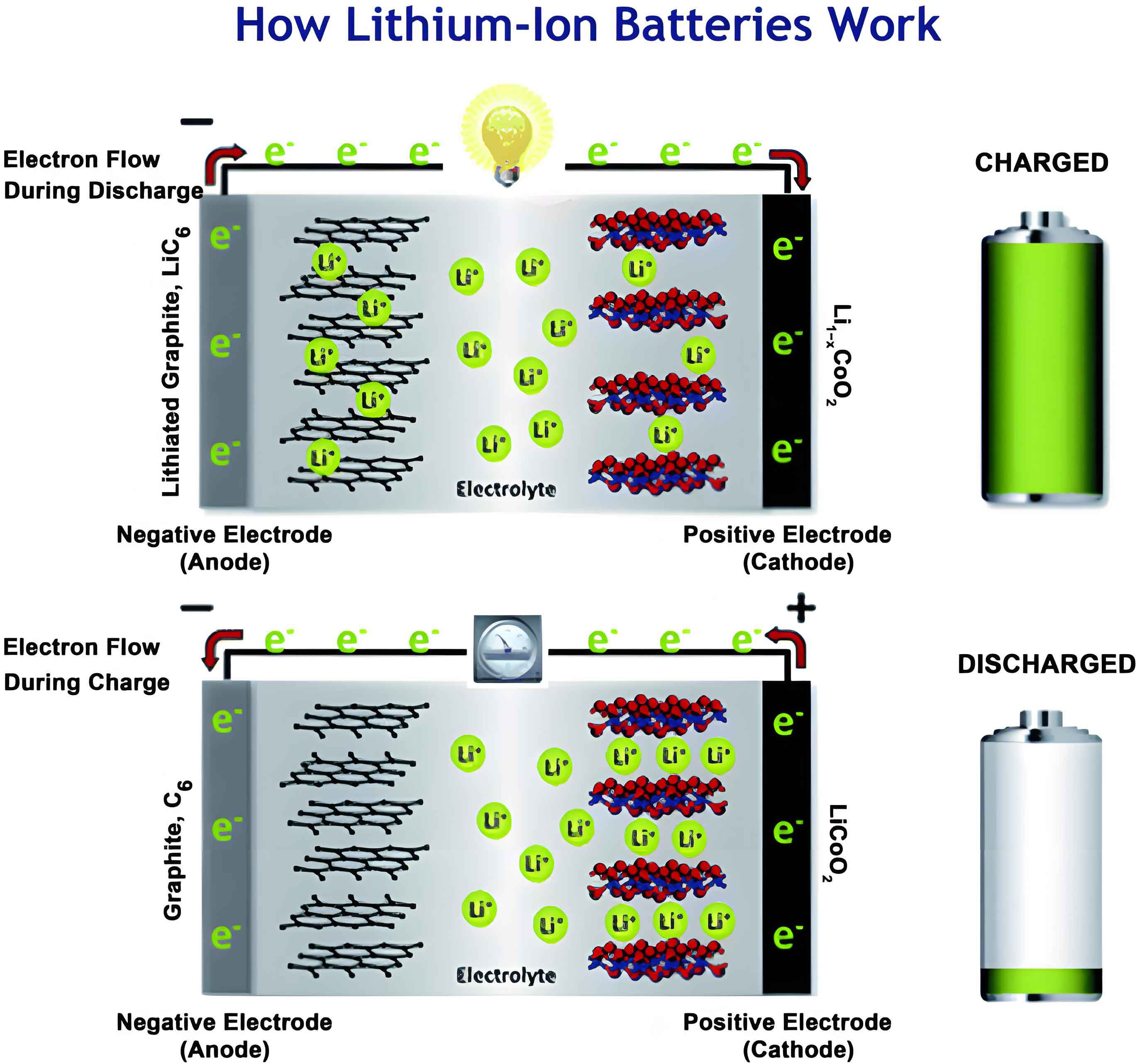
A typical lithium-ion battery consists of a lithium-containing metal oxide cathode (e.g., LiCoO2, LiFePO4, NCM), a graphite-based anode, a porous separator, and a lithium salt dissolved in an organic solvent electrolyte. During charging, lithium ions are extracted from the cathode structure, migrate through the electrolyte, and insert into the layered structure of the graphite anode. This process is accompanied by the flow of electrons through the external circuit, storing electrical energy as chemical energy. Discharge reverses this process, with lithium ions moving back to the cathode, releasing energy.
The overall reaction in a graphite-based lithium-ion battery can be represented as:
Cathode: LiMO2 ⇌ Li1-xMO2 + xLi+ + xe–
Anode (Graphite): xLi+ + xe– + 6C ⇌ LixC6
Full Cell: LiMO2 + 6C ⇌ Li1-xMO2 + LixC6
where M represents transition metals like Co, Ni, Mn, Fe, etc. The performance and longevity of the lithium-ion battery are heavily influenced by the stability and kinetics of these intercalation/de-intercalation reactions at both electrodes.
2. Lithium Storage Mechanism in Graphite Anodes
Graphite has a layered structure where carbon atoms are arranged in hexagonal sheets (graphene layers) held together by weak van der Waals forces with an interlayer spacing of approximately 0.335 nm. Lithium storage occurs via intercalation, where Li+ ions insert between these graphene layers. The intercalation proceeds through distinct stages, forming a series of graphite intercalation compounds (GICs). The staging phenomenon is a hallmark of graphite electrochemistry in a lithium-ion battery.
The progressive lithiation can be described as follows:
Stage IV: Dilute LixC (x → 0) to LiC~72 (Solid solution)
Stage III: LiC~36 to LiC~27 (Two-phase region with Stage IV)
Stage II: LiC~18 to LiC~12 (Two-phase region with Stage III)
Stage I: LiC12 to LiC6 (Final two-phase region)
The final and most lithiated phase is LiC6, which corresponds to the theoretical capacity. The staging is evident in the voltage profile as characteristic plateaus. The reaction for full lithiation is:
$$ \text{C}_6 + \text{Li}^+ + e^- \rightleftharpoons \text{LiC}_6 $$
The theoretical gravimetric capacity (Qth) is calculated based on this 1:6 Li:C stoichiometry:
$$ Q_{th} = \frac{nF}{3.6 \times M_w} $$
where n is the number of electrons transferred per formula unit (1 for LiC6), F is Faraday’s constant (96485 C mol-1), and Mw is the molecular weight of the active material (72.06 g mol-1 for C6). This yields the well-known value of ~372 mAh g-1. The volumetric capacity is also high (~850 mAh cm-3), making graphite attractive for space-constrained applications.
A crucial aspect of graphite electrochemistry is the formation of the Solid Electrolyte Interphase (SEI) during the first charge cycle. Electrolyte components reduce at the graphite surface (around 0.8-0.2 V vs. Li/Li+), forming a passivating layer composed of inorganic species (e.g., Li2CO3, LiF, Li2O) and organic oligomers. A stable and ionically conductive SEI is essential as it prevents further electrolyte decomposition and exfoliation of graphite layers caused by solvent co-intercalation, but its formation irreversibly consumes Li+, leading to an initial capacity loss.
3. Advantages and Limitations of Graphite Anodes
Graphite’s dominance in commercial lithium-ion batteries is attributed to a compelling set of advantages, which are systematically compared against its key limitations in the table below.
| Advantages | Limitations / Challenges |
|---|---|
| Low Cost & Abundance: Natural and synthetic graphite sources are plentiful, enabling mass production. | Limited Theoretical Capacity: The 372 mAh g-1 ceiling restricts energy density improvements. |
| Excellent Electrochemical Stability: Operates at a safe potential (~0.1 V vs. Li/Li+) without lithium plating under normal conditions. | Moderate Rate Capability: Li+ diffusion within graphite layers and through the SEI can be slow, limiting fast-charge performance. |
| High Electronic & Thermal Conductivity: Facilitates efficient electron transport and heat dissipation within the electrode. | SEI Instability: The SEI can continuously grow and crack during cycling, consuming active lithium and electrolyte, leading to capacity fade. |
| Long Cycle Life: The intercalation mechanism causes minimal structural damage, supporting thousands of cycles. | Solvent Co-intercalation: Certain solvents (e.g., propylene carbonate) can co-intercalate with Li+, causing graphite exfoliation and failure. |
| Well-understood Processing: Established electrode manufacturing and slurry casting techniques. | Low-Temperature Performance: Li+ diffusion and charge transfer kinetics significantly slow down at sub-zero temperatures. |
The modification strategies discussed herein aim to directly address these limitations, particularly those related to rate performance, cycle life, and interfacial stability, thereby enhancing the overall performance of the lithium-ion battery.
4. Modification Strategies for Graphite Anodes
4.1 Material Doping and Compositing
This strategy involves incorporating heteroatoms or secondary active/conductive phases into the graphite matrix. The goals are to increase capacity, improve electronic conductivity, enhance Li+ diffusion, or stabilize the electrode structure.
a) Heteroatom Doping (B, N, P, S): Introducing elements like nitrogen or boron into the carbon lattice alters the electronic structure and creates defects. For instance, N-doping (pyridinic or pyrrolic N) introduces electron-rich sites that can enhance Li+ adsorption. The binding energy (Ebind) of Li can be approximated through computational studies, often showing stronger interaction with doped sites compared to pristine graphene.
$$ E_{\text{bind}} = E_{\text{(doped C+Li)}} – E_{\text{(doped C)}} – E_{\text{(Li)}} $$
A negative Ebind indicates favorable adsorption. Doping can also expand the interlayer spacing slightly, facilitating Li+ ingress/egress.
b) Composite Anodes (Si/G, Sn/G, Metal Oxide/G): Combining high-capacity materials (Si: ~4200 mAh g-1, Sn: ~994 mAh g-1) with graphite leverages the capacity of the former and the cyclability of the latter. The graphite matrix buffers the massive volume change of the alloying materials. The composite capacity (Qcomp) can be estimated by the rule of mixtures:
$$ Q_{\text{comp}} = w_{\text{graphite}} \cdot Q_{\text{graphite}} + w_{\text{additive}} \cdot Q_{\text{additive}} $$
where w represents the weight fraction. The challenge is maintaining electrical connectivity and structural integrity during the repeated expansion/contraction of the additive.
| Doping/Composite Type | Mechanism / Benefit | Typical Performance Gain | Key Challenge |
|---|---|---|---|
| Nitrogen Doping | Enhances electronic conductivity, creates active sites for Li+ storage. | Increased reversible capacity (up to ~400 mAh g-1), improved rate performance. | Precise control of doping level and configuration; may increase first-cycle loss. |
| Silicon-Graphite Composite | Graphite buffers Si volume change; Si provides high capacity. | Capacity > 500 mAh g-1 achievable; cycle life improved vs. pure Si. | Managing severe volume expansion of Si; maintaining stable SEI on composite. |
| Metal Oxide (e.g., Fe3O4) Composite | Conversion reaction provides high capacity; graphite improves conductivity. | High initial capacity; improved cycling stability of the conversion material. | Large voltage hysteresis, low initial Coulombic efficiency, potential particle aggregation. |
4.2 Surface Coating
Applying a thin, conformal layer on graphite particles is a highly effective method to engineer the electrode-electrolyte interface. The coating acts as a physical barrier, a tailored SEI precursor, or a functional layer.
a) Carbon Coating (Amorphous Carbon, Hard Carbon): A carbon coating can prevent direct contact between graphite and electrolyte, suppressing solvent co-intercalation. It also provides additional conductive pathways and can accommodate volume changes. The coating thickness (t) is critical; an optimal thickness minimizes impedance while providing full coverage. The effective ionic conductivity (σeff) through the coating influences kinetics:
$$ R_{\text{coat}} \propto \frac{t}{\sigma_{\text{eff}} A} $$
where A is the surface area. An overly thick coating increases resistance.
b) Metal/Metal Oxide Coating (Al2O3, ZnO, MoOx): These inorganic coatings, often applied via atomic layer deposition (ALD) or wet chemistry, are excellent at scavenging HF from electrolyte decomposition, protecting the graphite. They can also promote the formation of a more stable, inorganic-rich SEI.
c) Polymer Coating: Soft polymer coatings (e.g., gelatin, polyaniline) can accommodate volume changes and provide a flexible framework for a stable SEI.
| Coating Material | Primary Function | Impact on Graphite Anode | Consideration |
|---|---|---|---|
| Amorphous Carbon | Physical barrier, additional Li+ storage, conductivity enhancer. | Improves first-cycle efficiency, rate capability, and cycling stability. Suppresses exfoliation. | Coating must be uniform and thin; may add irreversible capacity if too thick/porous. |
| Al2O3 (nanolayer) | HF scavenger, promotes LiF-rich SEI, protects surface. | Significantly improves cycle life, especially at elevated temperatures. Enhances thermal stability. | ALD is precise but costly; wet-chemical methods need careful control to avoid insulation. |
| Conductive Polymer (e.g., Polypyrrole) | Flexible interface, enhances surface conductivity, modulates SEI formation. | Improves rate performance and cycle life, particularly for low-crystallinity graphite. | Long-term stability of the polymer in the electrochemical environment. |
4.3 Structural Design
Modifying the macroscopic and microscopic morphology of graphite particles can drastically improve Li+ transport kinetics and alleviate internal stress.
a) Particle Shape and Size Engineering (Spherical vs. Flake): Spherical graphite (SG) offers higher tap density, leading to higher volumetric energy density in the lithium-ion battery. More importantly, its isotropic shape creates a more uniform current distribution and shorter, less tortuous Li+ diffusion paths compared to anisotropic flake graphite. The tortuosity (τ) of an electrode, affecting Li+ transport, is generally lower for spherical particle packs:
$$ D_{\text{eff}} = \frac{D_0 \epsilon}{\tau} $$
where Deff is the effective diffusion coefficient, D0 is the bulk coefficient, and ε is the porosity. Lower τ (as with SG) yields higher Deff.
b) Pore/Channel Creation (Chemical Etching): Controlled etching (e.g., with KOH, air) creates micro- or nano-channels on graphite particles. These channels serve as “highways” for rapid Li+ access to the interior, significantly boosting rate capability. The created surface area also provides more reaction sites but must be balanced against potential increases in irreversible SEI formation.
c) Expanded Graphite (EG): By inserting and removing chemical species between graphene layers, the interlayer spacing can be permanently increased. This reduces the diffusion barrier for Li+ intercalation. The expansion ratio and the preservation of long-range order are critical for maintaining good electronic conductivity.
| Structural Modification | Design Principle | Performance Outcome | Trade-off / Challenge |
|---|---|---|---|
| Spherical Graphite | Improve packing density and create isotropic Li+ pathways. | Higher electrode density, better rate performance, more stable cycling under fast charge. | Spheroidization process adds cost; specific surface area may increase. |
| Etched Graphite (Porous) | Create internal channels for rapid ionic transport. | Dramatically enhanced rate capability (high C-rate capacity). | Increased surface area leads to higher first-cycle loss; mechanical strength may decrease. |
| Expanded Graphite | Increase interlayer spacing to lower Li+ diffusion barrier. | Improved kinetics, especially at low temperatures; can accommodate volume change better. | Risk of reduced electronic conductivity and tap density if over-expanded. |
4.4 Electrolyte Engineering and Interphase Modification
Since graphite’s performance is intensely coupled with its interface, tailoring the electrolyte is a powerful, non-invasive modification strategy. The goal is to form a stable, thin, and ionically conductive SEI.
a) Electrolyte Additives: Small amounts (0.5-5 wt%) of functional additives can preferentially reduce to form a robust SEI. Classic examples include:
- Vinylene Carbonate (VC): Polymerizes to form a polycarbonate-based flexible SEI layer.
- Fluoroethylene Carbonate (FEC): Reduces to form a LiF-rich SEI, excellent for stability.
- LiNO3: Although more common in Li-S or Li-metal batteries, it can modify graphite SEI in certain electrolytes.
The additive reduction potential should be higher than the solvent reduction potential (Ered,add > Ered,solv) to ensure preferential decomposition.
b) Solvent and Salt Selection: Using solvents with weak solvating power (e.g., some ethers, fluorinated ethers) can create an anion-derived, inorganic-rich SEI, which often has higher ionic conductivity. Salts like LiDFOB or LiBF4 can lead to more stable interphases compared to the standard LiPF6 under stressful conditions.
c) Concentrated Electrolytes and Localized High-Concentration Electrolytes (LHCE): Increasing salt concentration changes the Li+ solvation structure, shifting reduction from solvent-dominated to anion-dominated. This leads to a stable, inorganic SEI (rich in LiF, Li3N) that drastically improves graphite cycling, especially at high voltages and temperatures. The enhanced stability can be correlated with the increased contribution of anion to the lowest unoccupied molecular orbital (LUMO) of the solvation sheath.
| Electrolyte Strategy | Mechanism of Action | Benefit for Graphite Anode | Consideration |
|---|---|---|---|
| SEI-Forming Additives (VC, FEC) | Preferentially reduce to form a dense, protective film before solvent decomposition. | Greatly improves first-cycle efficiency, cycle life, and suppresses gas generation. | Optimal dosage is critical; overuse can increase impedance or cause gelling. |
| Weakly Solvating Solvents / LHCE | Promote anion reduction, forming inorganic-rich, conductive SEI. | Enables outstanding cycling stability, excellent fast-charge performance, and wide temperature operation. | Higher viscosity and cost; compatibility with cathode materials must be verified. |
| Novel Lithium Salts (e.g., LiDFOB) | Salts decompose to form boron- and fluorine-containing species that stabilize the interface. | Improves high-temperature storage and cycling performance; often synergizes with additives. | Generally more expensive than LiPF6; long-term stability data is evolving. |
5. Summary and Perspective
The relentless pursuit of higher energy density, faster charging, longer life, and improved safety continues to drive innovation in lithium-ion battery technology. While next-generation anode materials like silicon and lithium metal are under intense development, graphite remains the workhorse due to its unmatched combination of performance, cost, and reliability. The modification strategies reviewed here—doping/compositing, surface coating, structural design, and electrolyte engineering—are not mutually exclusive but are increasingly used in tandem to push the performance boundaries of graphite anodes.
A future direction involves the intelligent integration of multiple strategies. For example, a spherical, porosity-engineered graphite particle coated with a nanolayer of Al2O3 and used in an LHCE electrolyte with tailored additives could potentially meet the extreme demands of fast-charge electric vehicles. Computational modeling and advanced in-situ characterization techniques will play pivotal roles in designing these hierarchical structures and understanding interfacial dynamics at an atomic level.
Ultimately, the choice of modification strategy depends on the specific application requirements of the lithium-ion battery—be it energy density, power density, cycle life, cost, or operating temperature. The rich toolbox available for graphite anode modification ensures its continued relevance and provides a robust pathway for the incremental yet significant advancement of commercial lithium-ion batteries in the coming decades.