
This paper investigates the thermal runaway propagation characteristics within LiFePO4 battery clusters, a critical safety concern for grid-scale energy storage systems. Containerized energy storage cabins are typically constructed from densely packed battery clusters comprising multiple modules. In extreme scenarios, a thermal runaway event in a single module can propagate, leading to catastrophic failure of the entire cluster. Therefore, a detailed understanding of the thermal field evolution and propagation dynamics under overcharge conditions is essential. This study combines experimental analysis of a LiFePO4 battery module with high-fidelity multi-physics simulation to model and analyze the thermal runaway propagation within a full battery cluster.
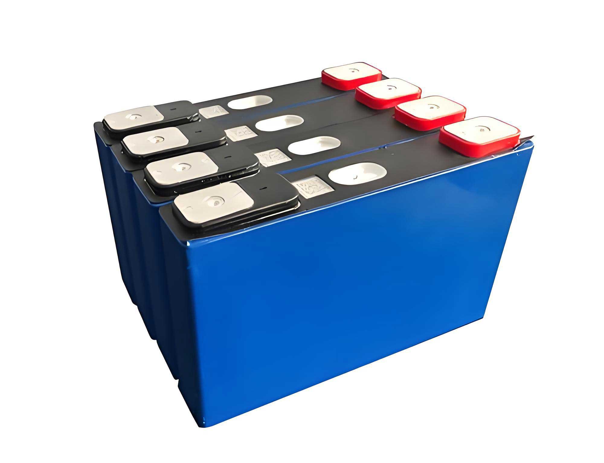
First, the underlying mechanisms of overcharge-induced thermal runaway in a LiFePO4 battery are analyzed. An experimental platform for an 8.8 kWh LiFePO4 battery module was established to conduct overcharge tests at different rates. The experimental results delineated two distinct failure modes: a gas venting mode at a 0.4C overcharge rate and a flaming combustion mode at a 0.5C rate. Based on these experimental findings, a comprehensive thermal-field simulation model for a battery cluster was developed using COMSOL Multiphysics software. The model incorporates joule heating and exothermic chemical side reactions to simulate the thermal runaway initiation and subsequent heat transfer within the cluster. The simulation results reveal that a single module overcharged at 0.4C does not trigger thermal runaway in neighboring modules, although the module directly beneath is most affected. Conversely, a 0.5C overcharge leads to a rapid temperature rise on the upper surface of the failing module, which acts as a thermal source that can sequentially trigger thermal runaway in modules stacked above it, resulting in vertical propagation through the LiFePO4 battery cluster. This research provides theoretical and technical insights crucial for designing advanced thermal safety protection systems in energy storage power stations.
1. Introduction
Lithium Iron Phosphate (LiFePO4) batteries are widely adopted in grid energy storage applications due to their high energy density, long cycle life, and inherent safety advantages over other lithium-ion chemistries. Despite their relative safety, LiFePO4 batteries are not immune to thermal runaway under abusive conditions. In energy storage systems (ESS), batteries are configured into modules and further aggregated into clusters within densely packed, often semi-enclosed, containers. This configuration, while space-efficient, exacerbates thermal management challenges. Among various failure triggers—mechanical, electrical, and thermal—overcharge represents a predominant risk in stationary ESS where batteries are in a static, managed environment. Although Battery Management Systems (BMS) are designed to prevent overcharge by monitoring State-of-Charge (SOC), vulnerabilities persist due to cell aging, inconsistencies within a LiFePO4 battery pack, electromagnetic interference, or BMS failure. A single overcharged LiFePO4 battery module can initiate a thermal runaway sequence, potentially propagating to adjacent modules and culminating in a large-scale fire. Consequently, studying the thermal runaway propagation behavior within a LiFePO4 battery cluster is of paramount importance for risk assessment and safety design. Experimental testing on full-scale clusters is prohibitively expensive and hazardous. Therefore, this study employs a combined experimental and simulation approach. We first conduct controlled overcharge tests on a single LiFePO4 battery module to characterize its thermal behavior. These results then inform and validate a high-fidelity 3D thermal simulation model, which is subsequently scaled to simulate propagation within a multi-module LiFePO4 battery cluster. This methodology offers a cost-effective and insightful pathway to understanding complex thermal hazards in ESS.
2. Thermal Runaway Mechanism in LiFePO4 Batteries During Overcharge
2.1 Heat Generation Mechanisms
During normal operation of a LiFePO4 battery, internal heat generation is relatively modest and stems from reversible reaction heat, polarization heat, and joule heating. However, during overcharge, lithium ions are continuously extracted from the cathode and plated onto the anode. This process leads to the thickening of the Solid-Electrolyte Interphase (SEI) layer and a continuous increase in internal resistance, resulting in significant joule heating ($Q_j$). The heat generation rate from joule heating is given by:
$$Q_j = I^2 R$$
where $I$ is the charging current and $R$ is the internal resistance of the LiFePO4 battery. As the temperature rises due to this heat accumulation, it can trigger a series of exothermic chemical side reactions within the LiFePO4 battery. The sequence and approximate onset temperatures for these reactions are summarized below:
| Reaction | Typical Onset Temp. (T) | Description |
|---|---|---|
| SEI Decomposition | T > 90°C | Breakdown of the SEI layer on the anode. |
| Anode-Electrolyte Reaction | T > 120°C | Reaction between lithiated graphite and electrolyte. |
| Cathode Decomposition | T > 170°C | Decomposition of the LiFePO4 cathode material. |
| Electrolyte Decomposition | T > 200°C | Decomposition of the organic electrolyte solvent. |
2.2 Modeling Exothermic Side Reactions
The total heat generation from chemical side reactions ($Q_s$) is the sum of the heat from each individual reaction. These reactions are typically modeled using Arrhenius kinetics. The key reactions and their governing equations are as follows:
1. SEI Decomposition:
$$Q_{sei} = H_{sei} \cdot W_c \cdot R_{sei}(T, C_{sei})$$
$$R_{sei}(T, C_{sei}) = A_{sei} \cdot (C_{sei})^{m_{sei}} \cdot \exp\left(\frac{-E_{a,sei}}{RT}\right)$$
$$\frac{dC_{sei}}{dt} = -R_{sei}$$
2. Reaction between Anode and Electrolyte:
$$Q_{ne} = H_{ne} \cdot W_c \cdot R_{ne}(T, C_{ne}, t)$$
$$R_{ne}(T, C_{ne}, t) = A_{ne} \cdot (C_{ne})^{m_{ne}} \cdot \exp\left(\frac{-E_{a,ne}}{RT}\right) \cdot \exp\left(\frac{-t}{t_{sei,ref}}\right)$$
$$\frac{dt_{sei}}{dt} = R_{ne}, \quad \frac{dC_{ne}}{dt} = -R_{ne}$$
3. Cathode Decomposition Reaction:
$$Q_{pe} = H_{pe} \cdot W_p \cdot R_{pe}(T, b)$$
$$R_{pe}(T, b) = A_{pe} \cdot b^{m_{pe1}} \cdot (1-b)^{m_{pe2}} \cdot \exp\left(\frac{-E_{a,pe}}{RT}\right)$$
$$\frac{db}{dt} = R_{pe}$$
4. Electrolyte Decomposition:
$$Q_{ele} = H_{ele} \cdot W_e \cdot R_{ele}(T, C_{ele})$$
$$R_{ele}(T, C_{ele}) = A_{ele} \cdot (C_{ele})^{m_{ele}} \cdot \exp\left(\frac{-E_{a,ele}}{RT}\right)$$
$$\frac{dC_{ele}}{dt} = -R_{ele}$$
Where $H_x$, $A_x$, $E_{a,x}$, and $m_x$ are the reaction enthalpy, pre-exponential factor, activation energy, and reaction order for reaction $x$, respectively. $W_c$, $W_p$, $W_e$ are the mass concentrations of carbon, cathode material, and electrolyte. $C_{sei}$, $C_{ne}$, $C_{ele}$, and $b$ are state variables representing the progress of each reaction. The total side reaction heat is:
$$Q_s(t) = Q_{sei}(t) + Q_{ne}(t) + Q_{pe}(t) + Q_{ele}(t)$$
2.3 Heat Transfer Modes
Heat dissipation within a LiFePO4 battery cluster occurs via convection and radiation. Convective heat transfer ($q_{conv}$), which can be natural or forced, is described by Newton’s law of cooling:
$$q_{conv} = h (T_s – T_{\infty})$$
where $h$ is the convective heat transfer coefficient, $T_s$ is the surface temperature, and $T_{\infty}$ is the ambient temperature. Radiative heat transfer ($q_{rad}$) follows the Stefan-Boltzmann law:
$$q_{rad} = \delta \sigma A_1 F_{12} (T_a^4 – T_b^4)$$
where $\delta$ is the emissivity, $\sigma$ is the Stefan-Boltzmann constant, $A_1$ is the area of surface 1, $F_{12}$ is the view factor, and $T_a$, $T_b$ are the absolute temperatures of the surfaces.
3. Overcharge Experiment on a LiFePO4 Battery Module
3.1 Experimental Setup
Overcharge tests were conducted on a commercial 8.8 kWh LiFePO4 battery module within a standard 12-meter energy storage container. The module consisted of 32 prismatic cells (8 in series, 4 in parallel), with a nominal voltage of 25.6 V and a capacity of 344 Ah. Six K-type thermocouples were attached to the geometric centers of each primary surface of the module (top, bottom, front, back, left, right) to monitor temperature evolution during the test. The module was subjected to constant current overcharge at rates of 0.4C (approximately 138 A) and 0.5C (approximately 172 A) until failure.
3.2 Experimental Results and Analysis
The experiments revealed two distinct failure modes for the LiFePO4 battery module, dependent on the overcharge rate.
0.4C Overcharge: The module exhibited significant gas venting through safety valves, releasing white smoke. No open flame was observed. The temperature profile, as shown in the data table below, indicated that the bottom surface temperature ($T_2$) peaked at approximately 210°C, while temperatures on other surfaces remained below 65°C. This is attributed to direct conductive heat transfer from the internal cells to the module’s bottom casing.
0.5C Overcharge: The failure escalated to flaming combustion. After an initial gas venting phase, an open flame erupted from the module at around 2100 seconds. Consequently, the thermal profile shifted dramatically. The flame impingement caused the top surface temperature ($T_1$) to soar to over 530°C within 100 seconds, while other surfaces reached temperatures around 200°C due to radiant heat.
| Overcharge Rate | Failure Mode | Peak Temp., Top (T1) | Peak Temp., Bottom (T2) | Peak Temp., Other Surfaces |
|---|---|---|---|---|
| 0.4C | Gas Venting (No Flame) | ~65°C | ~210°C | < 65°C |
| 0.5C | Flaming Combustion | > 530°C | ~210°C (pre-fire) | ~200°C |
4. Development of Thermal Simulation Model for LiFePO4 Battery Cluster
4.1 Model Geometry and Mesh
Based on the experimental module dimensions (420 mm x 600 mm x 320 mm), a 3D geometric model was created. A full battery cluster model was then constructed, consisting of two columns and seven rows, totaling 14 identical modules, with overall dimensions of 840 mm x 600 mm x 2240 mm. The geometry was discretized using a physics-controlled mesh in COMSOL to ensure computational accuracy and efficiency.
4.2 Governing Equations and Model Parameters
The energy balance within the LiFePO4 battery is governed by the heat conduction equation with a volumetric heat source:
$$\rho C_p \frac{\partial T}{\partial t} = \nabla \cdot (k \nabla T) + S$$
where $\rho$, $C_p$, and $k$ are the density, specific heat capacity, and thermal conductivity tensor of the battery material, respectively. $S$ is the volumetric heat generation rate. For the 0.4C simulation, $S = Q_j + Q_s$, combining joule heating and the Arrhenius-based side reaction models. For the 0.5C simulation, where flaming combustion occurred, the side reaction model alone was insufficient. Therefore, a time-dependent heat source function $S(t)$ was applied to the module surfaces, calibrated to replicate the experimental surface temperature profiles (particularly the high top-surface temperature). Non-overcharged modules in the cluster were modeled with a low, constant heat source representing normal operation. The key thermophysical properties of the LiFePO4 battery module are listed below.
| Component | Density (kg/m³) | Specific Heat (J/(kg·K)) | Thermal Conductivity (W/(m·K)) |
|---|---|---|---|
| Module Case (Aluminum) | 2702 | 903 | 238 (Isotropic) |
| Cell (Anisotropic) | 2405 | 1329 | k_x = 3.72 |
| k_y = 26.0 | |||
| k_z = 28.0 |
The parameters for the chemical kinetics model of the LiFePO4 battery side reactions are as follows:
| Reaction | ΔH (J/g) | A (s⁻¹) | Ea (J/mol) |
|---|---|---|---|
| SEI Decomposition | 257 | 1.667 × 10¹⁵ | 1.351 × 10⁵ |
| Anode-Electrolyte | 1714 | 2.5 × 10¹³ | 1.351 × 10⁵ |
| Cathode Decomposition | 146 | 1.05 × 10¹¹ | 1.136 × 10⁵ |
| Electrolyte Decomposition | 155 | 5.1 × 10²⁵ | 2.74 × 10⁵ |
5. Simulation Results and Analysis of Thermal Runaway Propagation
5.1 Single Module Overcharge Simulation
The model for the single LiFePO4 battery module at 0.4C overcharge was first validated against experimental data. The simulated temperature evolution showed good agreement, capturing the high bottom-surface temperature (~210°C) and the lower temperatures on other surfaces. The slight over-prediction of bottom temperature and under-prediction of top temperature were attributed to model simplifications, such as neglecting heat loss during venting and the heating effect of hot gases, respectively. The simulation confirmed that the primary heat flow from the failing LiFePO4 battery module at 0.4C is downward via conduction.
5.2 Cluster Propagation Simulation
Propagation was simulated by designating module #4 (in the second row from the bottom) as the initiation point.
Scenario 1: 0.4C Overcharge Initiation. The simulation results showed that the thermal abuse of module #4 did not propagate to other modules in the LiFePO4 battery cluster. The maximum temperature of adjacent modules remained below the critical thresholds for side reaction initiation. The module directly below (#11) experienced the most significant temperature rise due to conductive heat transfer but did not enter thermal runaway. The overall hazard was contained.
Scenario 2: 0.5C Overcharge Initiation. The simulation revealed a clear vertical propagation path. The intense heat flux from the top surface of the failing module #4, modeled based on the experimental flame data, acted as a powerful thermal source for the module directly above it (#3). This caused module #3 to heat rapidly and enter thermal runaway. This process then repeated, with module #3 triggering module #2, and subsequently module #2 triggering module #1. The temperature evolution of modules #1 through #4 showed a clear sequential ignition pattern. Modules to the side and below experienced warming but did not reach critical conditions, indicating that propagation in this configuration is primarily upward due to the directionality of the flame and high-temperature plume from a flaming LiFePO4 battery failure.
| Initiation Condition | Propagation Occurrence | Primary Direction | Key Mechanism | Maximum Hazard |
|---|---|---|---|---|
| Single Module at 0.4C | No | N/A | Conductive heating (downward) | Localized module failure |
| Single Module at 0.5C | Yes | Upward | Radiative & convective heating from flame | Cascading failure of vertical stack |
6. Conclusion
This study integrated experimental testing and numerical simulation to investigate the thermal runaway propagation within a LiFePO4 battery cluster under overcharge conditions. The key findings are:
- Failure Mode Dependence on Rate: The overcharge rate critically determines the failure mode of a LiFePO4 battery module. At 0.4C, failure is characterized by gas venting with moderate, downward-focused heating. At 0.5C, failure escalates to flaming combustion, generating extreme temperatures (>530°C) on the module’s upper surface.
- Propagation Threshold: The transition from a contained single-module event to a propagating cluster event is linked to this change in failure mode. A gas-venting failure (0.4C) does not provide sufficient thermal impetus to trigger neighboring modules in a standard cluster configuration.
- Upward Propagation Pathway: A flaming failure (0.5C) creates a severe upward thermal threat. Simulation results demonstrate a sequential, upward propagation through vertically stacked modules in the LiFePO4 battery cluster, driven by flame impingement and radiant heat transfer from the burning module’s top surface.
- Design Implications: These insights are crucial for the safety design of LiFePO4-based energy storage systems. Mitigation strategies should focus on preventing overcharge, especially at higher rates, and implementing physical barriers or enhanced cooling between vertically stacked modules to interrupt the identified upward propagation path. Furthermore, placement of gas and fire detection/suppression systems should account for the vertical progression of hazard.
The developed model provides a valuable tool for assessing thermal risks and evaluating the effectiveness of different safety designs in LiFePO4 battery energy storage systems without conducting full-scale hazardous tests.