
The global transition towards sustainable energy systems has placed unprecedented importance on energy storage technologies. Among the various solutions, battery energy storage systems (BESS) have emerged as a critical enabler due to their scalability, rapid response, and declining costs. Within the spectrum of battery chemistries, lithium iron phosphate (LiFePO4 or LFP) batteries have become a dominant choice for grid-scale applications. Their appeal lies in an exceptional combination of intrinsic safety, long cycle life, thermal stability, and cost-effectiveness. However, the large-scale deployment of lifepo4 battery systems introduces significant engineering challenges, with thermal management being paramount. The performance, longevity, and safety of a lifepo4 battery pack are profoundly sensitive to its operating temperature. Ineffective thermal management can lead to accelerated degradation, reduced capacity, power limitations, and in extreme cases, thermal runaway. Therefore, a rigorous analysis and optimization of the thermal behavior within lifepo4 battery cabinets is not merely an academic exercise but a fundamental requirement for reliable and economical energy storage.
This article presents a comprehensive investigation into the thermal dynamics of a containerized lifepo4 battery energy storage system. Utilizing computational fluid dynamics (CFD) simulation, we model the coupled temperature and flow fields under typical operational loads. The analysis reveals inherent inhomogeneities in temperature distribution stemming from airflow design limitations. Subsequently, we propose and evaluate two sequential structural optimizations aimed at homogenizing the internal climate. The goal is to ensure that every cell within the massive lifepo4 battery assembly operates within a narrow, optimal temperature band, thereby maximizing system efficiency and lifespan.
Theoretical Foundation of Battery Heat Generation and Transfer
To accurately simulate the thermal behavior of a lifepo4 battery system, one must first understand the sources of heat and the mechanisms of its dissipation. The total heat generated within a lifepo4 battery cell during charge or discharge is primarily attributed to irreversible processes.
Heat Generation in LiFePO4 Cells
The total heat generation rate (Ptotal) is commonly expressed as the sum of reaction heat (Pr), polarization heat (Pp), and Joule heat (Pj).
$$P_{\text{total}} = P_r + P_p + P_j$$
For a lifepo4 battery operating within its standard temperature window (typically -20°C to 55°C, optimally 10°C to 35°C), the reversible reaction heat is negligible compared to the irreversible components. The dominant sources are the Joule (or Ohmic) heat and the polarization heat, both arising from the cell’s internal resistance to current flow. These can be combined and modeled as:
$$P = I^2 R_{\text{internal}}$$
Where \(I\) is the current and \(R_{\text{internal}}\) is the effective internal resistance, which itself is a function of State of Charge (SOC), temperature, and aging. For simplification in steady-state thermal analysis, an average internal resistance value is often used. The volumetric heat generation rate (\(q”\)), a crucial input for CFD simulations, is then calculated by dividing the total heat generation power by the cell volume (\(V_{\text{cell}}\)):
$$q” = \frac{P}{V_{\text{cell}}} = \frac{I^2 R_{\text{internal}}}{V_{\text{cell}}}$$
This volumetric heat source term is applied uniformly within the cell volume in the simulation model.
Heat Transfer Mechanisms
The heat generated within the lifepo4 battery cells must be transported away to the environment to prevent excessive temperature rise. This occurs through three fundamental modes:
- Conduction: Heat transfer through solid materials (e.g., from the cell core to its casing, through busbars, and into module structures). It is governed by Fourier’s law:
$$\mathbf{q} = -k \nabla T$$
Where \(\mathbf{q}\) is the heat flux vector, \(k\) is the thermal conductivity of the material, and \(\nabla T\) is the temperature gradient.
- Convection: The primary mode for transferring heat from the battery surfaces to the cooling air. It is described by Newton’s law of cooling:
$$Q = h A (T_s – T_f)$$
Where \(Q\) is the convective heat transfer rate, \(h\) is the convective heat transfer coefficient, \(A\) is the surface area, \(T_s\) is the surface temperature, and \(T_f\) is the fluid (air) temperature.
- Radiation: Heat transfer via electromagnetic waves between surfaces at different temperatures. For the moderate temperature ranges of a lifepo4 battery system, its contribution is typically an order of magnitude smaller than forced convection and is often neglected in initial analyses to simplify the model.
$$Q_r = \sigma \epsilon A (T_s^4 – T_{\text{surr}}^4)$$
In a forced-air cooled lifepo4 battery cabinet, the dominant heat removal path is: conduction within cells and modules → convection to the forced air stream → advection of heated air out of the system.
System Modeling and Simulation Setup
Our study focuses on a commercial grid-scale lifepo4 battery cabinet. The fundamental building block is a 3.2V, 230Ah prismatic LiFePO4 cell. Multiple cells are connected in series and parallel to form a module, and multiple modules are stacked vertically inside a cabinet. A centralized HVAC system provides cooled air to the top of the cabinet.
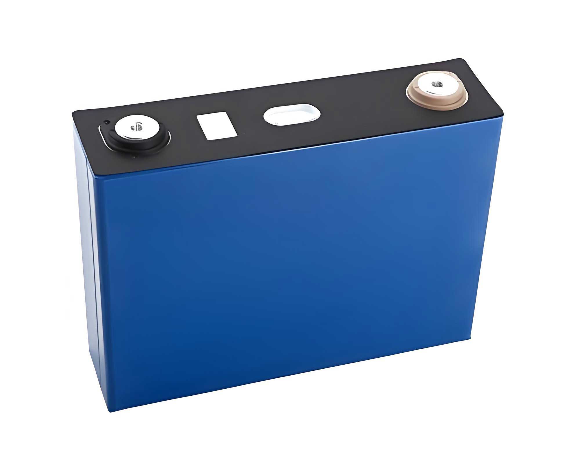
The thermal properties of the different components within the lifepo4 battery cell are critical for an accurate simulation. We define these properties as follows:
| Component | Material | Specific Heat Capacity [J/(kg·K)] | Thermal Conductivity [W/(m·K)] |
|---|---|---|---|
| Positive Electrode | LiFePO4 Composite | 1569 | 1.58 |
| Negative Electrode | Graphite Composite | 1437 | 1.04 |
| Separator | Polyethylene-based | 1978 | 0.33 |
| Positive Tab | Aluminum | 951 | 237.5 |
| Negative Tab | Copper | 385 | 400.0 |
| Cell Case | Aluminum/Plastic | ~900 | ~200 |
For the CFD simulation, a simplified geometry was created. The complex internal structure of the lifepo4 battery cell is homogenized into a solid block with anisotropic thermal properties, approximating the layered structure. Modules and the full cabinet are assembled from these simplified cells. The simulation parameters are set based on a typical 1C discharge scenario:
| Parameter | Value | Description |
|---|---|---|
| Cell Volumetric Heat Gen. (q”) | ~1667 W/m³ | Calculated from I²R, assuming Rinternal ≈ 0.23 mΩ. |
| Air Inlet Velocity | 7.8 m/s | Supplied by the central HVAC duct. |
| Air Inlet Temperature | 25°C (298 K) | Ambient cooling air temperature. |
| Turbulence Model | Standard k-ε | For modeling turbulent airflow in the cabinet. |
| Cabinet Walls | Adiabatic | Assuming well-insulated exterior. |
Analysis of Baseline (Original) Configuration
The initial simulation of the baseline cabinet design reveals significant thermal non-uniformity, a common challenge in densely packed lifepo4 battery systems. The airflow enters from a central duct at the top of the cabinet and is intended to flow down through the channels at the front and rear of the battery modules.
Flow Field Characteristics: The velocity vector plot shows a critical issue. A large portion of the high-velocity cooling air (over 8 m/s) passes over the top module and exits almost directly out of the front and rear openings of the cabinet near the top. Due to momentum and pressure effects, insufficient air is “pulled” down into the lower sections of the vertical channels. Consequently, the airflow velocity in the channels serving the middle and lower modules drops significantly, often below 2 m/s. This creates a stark imbalance in the convective cooling capacity available to different module layers.
Temperature Field Consequences: The uneven airflow directly translates into an uneven temperature field. The modules in the direct path of the high-speed air (top layer) remain close to the inlet air temperature. However, modules in the middle layers (e.g., layers 2, 3, 4, and 7 in an 8-layer stack), which receive stagnant or low-velocity air, exhibit the highest temperatures. The simulation identifies “hot spots” in these regions.
| Thermal Metric | Baseline Configuration |
|---|---|
| Maximum Module Temperature | 40.55°C |
| Minimum Module Temperature (at inlet) | 17.85°C |
| Global Temperature Delta (ΔT) | 22.70°C |
| Location of Max Temperature | Middle Layers (2,3,4,7) |
While the absolute maximum temperature of 40.55°C is within the safe operating limit for a lifepo4 battery, the 22.7°C temperature differential is highly problematic. Such a large ΔT leads to:
- State of Charge (SOC) Imbalance: Cells at different temperatures have different internal resistances and electrochemical kinetics, causing them to charge/discharge at slightly different rates over time.
- Accelerated & Divergent Aging: The hotter cells degrade faster than the cooler ones, leading to increasing capacity and impedance mismatch within the lifepo4 battery pack.
- Reduced Usable Capacity: The Battery Management System (BMS) must limit operation based on the hottest cell, meaning the cooler cells are under-utilized.
Therefore, optimizing the lifepo4 battery cabinet’s thermal design is essential not just for safety, but for performance and economics.
Optimization Strategy I: Front/Rear Door Baffle Modification
The root cause of the problem is the premature escape of cooling air. The first optimization addresses this by modifying the front and rear cabinet doors to act as baffles or shrouds. The doors are extended or designed to seal against the cabinet frame, closing off the large openings near the top. An exhaust vent is created at the very bottom of the door.
Mechanism: This modification fundamentally alters the pressure distribution within the front and rear plenums (air channels). By blocking the easy exit path near the top, the incoming air is forced to travel down the entire height of the channel before it can exit through the bottom vent. This increases the static pressure in the upper part of the channel, driving more air to flow through the battery modules themselves and improving the distribution down the stack.
Simulation Results after Optimization I:
| Thermal Metric | After Door Baffle Modification | Change from Baseline |
|---|---|---|
| Maximum Module Temperature | 38.75°C | ↓ 1.80°C |
| Minimum Module Temperature | 17.85°C | No change |
| Global Temperature Delta (ΔT) | 20.90°C | ↓ 1.80°C |
Flow Field Improvement: The velocity vectors confirm that a greater volume of air is now directed down the channels. The high-velocity region (4.8 – 7.6 m/s) extends deeper into the cabinet. The airflow through the middle modules is noticeably improved, which directly correlates with the reduction in their temperature. The maximum air velocity within the cabinet even increased slightly to 9.69 m/s, indicating more efficient use of the cooling air’s kinetic energy.
This first step successfully lowers the peak temperature and slightly compresses the temperature range within the lifepo4 battery cabinet. However, a ΔT of 20.9°C indicates that significant inhomogeneity persists, particularly for modules at specific heights where airflow might be transitioning or where “dead zones” remain.
Optimization Strategy II: Integrated Air Guide Vanes
While the door baffle ensures air travels down the plenum, it doesn’t actively manage how that air interacts with each specific lifepo4 battery module layer. The second optimization introduces strategically placed air guide vanes (or deflector plates) on the inner surface of the modified doors.
Mechanism: These vanes are angled to intercept a portion of the downward-flowing air in the plenum and deflect it horizontally into the gaps between battery module layers. Their placement and angle are designed based on the identified hot spots from the previous simulations. For instance, vanes are positioned opposite the middle layers where temperatures remained highest after the first optimization. The vanes act to “steal” air from the main vertical flow and inject it precisely where needed, breaking up stagnant zones and ensuring more uniform lateral airflow across each lifepo4 battery module.
Simulation Results after Optimization II:
| Thermal Metric | After Adding Guide Vanes | Change from Opt. I | Change from Baseline |
|---|---|---|---|
| Maximum Module Temperature | 41.31°C | ↑ 2.56°C | ↑ 0.76°C |
| Minimum Module Temperature | 17.85°C | No change | No change |
| Key Improvement: Temperature Uniformity | Dramatically improved. Hot spots in middle layers (4-8) are significantly reduced. | ||
Analysis of Results: The second optimization presents a nuanced but critical result. The absolute maximum temperature slightly increased compared to Optimization I. This is because the guide vanes redistribute the cooling air more evenly across all modules, rather than allowing it to concentrate on cooling a few specific “hot” layers most effectively. The air is now working harder to cool the entire lifepo4 battery stack uniformly.
The most important outcome is the dramatic improvement in temperature uniformity. The large, contiguous hot zones disappear. The temperature contour plot shows a much more even color gradient from the top to the bottom of the cabinet. While the global ΔT (Max-Min) may not be the smallest metric here, the temperature difference between adjacent modules and across any single horizontal plane is minimized. This homogenization is far more valuable for the long-term health of the lifepo4 battery pack than a slight reduction in the absolute peak temperature if large gradients remain.
Comprehensive Discussion and Comparative Evaluation
The sequential optimization process demonstrates a systematic approach to thermal management for large-scale lifepo4 battery systems. The following table summarizes the impact of each stage:
| Design Stage | Primary Mechanism | Impact on Flow Field | Impact on Temperature Field | Overall Merit |
|---|---|---|---|---|
| Baseline | Uncontrolled air escape | High velocity only at top; stagnant zones below. | Large ΔT (22.7°C); distinct hot spots. | Unacceptable for long-term performance. |
| Opt. I: Door Baffle | Forces air down the plenum | Increased flow in middle channels; better vertical distribution. | Reduces peak temp and ΔT; hot spots remain but are cooler. | Significant improvement; addresses major flaw. |
| Opt. II: Guide Vanes | Active, targeted air redistribution | Breaks up stagnant zones; ensures lateral flow to each module layer. | Excellent uniformity; eliminates localized hot spots; homogenizes cell aging. | Optimal for pack longevity and reliability. |
Why Uniformity Trumps Absolute Minimum Peak: In a series-connected lifepo4 battery pack, the “weakest link” (hottest, highest resistance cell) dictates the performance of the entire string. A design with a slightly higher but uniform temperature (e.g., all cells at 40±2°C) is superior to a design with a lower peak but large gradients (e.g., cells ranging from 18°C to 39°C). In the uniform case, all cells age at a similar rate, SOC balances are easier to maintain, and the BMS can utilize more of the pack’s inherent capacity. The guide vane optimization moves decisively towards this ideal state for the lifepo4 battery system.
Generalizability of the Approach: The methodology—CFD simulation to diagnose flow/temperature maldistribution, followed by targeted structural modifications to guide airflow—is universally applicable to air-cooled lifepo4 battery enclosures. The specific design of baffles and vanes will vary with cabinet geometry, module arrangement, and fan/duct configuration, but the principles remain constant.
Conclusion and Future Perspectives
Effective thermal management is a cornerstone for unlocking the full potential of lithium iron phosphate chemistry in grid-scale energy storage. This study underscores that the inherent safety and longevity of a lifepo4 battery cell can be compromised at the system level by poor thermal design. Through detailed CFD analysis, we identified that non-uniform airflow distribution is a primary cause of significant temperature gradients within a standard battery cabinet.
We proposed and validated a two-stage optimization strategy. The first stage, implementing door baffles, successfully contained the cooling air and increased flow through the middle sections of the cabinet, reducing the peak temperature and overall ΔT. The second and more sophisticated stage, integrating angled guide vanes, provided active flow management. This final optimization achieved the primary goal of excellent temperature uniformity across the lifepo4 battery module stack, which is crucial for minimizing divergent aging and maximizing the system’s usable energy throughput over its lifetime.
Future work can build upon this foundation in several directions:
- Dynamic & Transient Analysis: Extending the simulation to model transient heat generation during real-world charge/discharge profiles, including rest periods.
- Multi-Objective Optimization: Using the CFD model in conjunction with optimization algorithms to automatically tune parameters like vane angle, position, and size to minimize a combined cost function (e.g., weighted sum of max temperature, ΔT, and fan power).
- Coupling with Electrical & Aging Models: Integrating the thermal model with electrical circuit models and semi-empirical aging laws to directly predict capacity fade and resistance growth over time under different thermal management schemes.
- Alternative Cooling Methods: Exploring the trade-offs for lifepo4 battery systems using liquid cooling or phase change materials (PCMs), especially for higher power density applications.
In conclusion, a physics-based, simulation-driven design approach is essential for developing robust thermal management systems. By ensuring a homogeneous and controlled thermal environment, we can safeguard the operational safety, enhance the performance, and ultimately guarantee the economic viability of large-scale lifepo4 battery energy storage installations, thereby supporting the broader integration of renewable energy sources into the global power grid.