
The widespread adoption of electrochemical energy storage systems, primarily built upon lithium-ion battery technology, is a cornerstone of modern energy strategies aimed at integrating renewable sources and enhancing grid stability. Among the various cathode chemistries, Lithium Iron Phosphate (LiFePO4) batteries are favored for large-scale stationary storage due to their perceived superior safety profile, long cycle life, and thermal stability. However, the catastrophic failure mode known as thermal runaway remains a critical risk. When subjected to electrical, thermal, or mechanical abuse, a LiFePO4 battery can undergo an uncontrollable self-heating reaction, leading to cell rupture, fire, and importantly, the release of significant volumes of flammable gas. In the confined spaces typical of containerized energy storage systems, these gases can accumulate, forming explosive mixtures that, upon ignition, can lead to devastating explosions, causing severe property damage and risking lives. Therefore, a comprehensive understanding of the gas generation behavior during the thermal runaway of LiFePO4 batteries is paramount for developing effective early warning systems, designing robust safety protocols, and mitigating secondary explosion hazards.
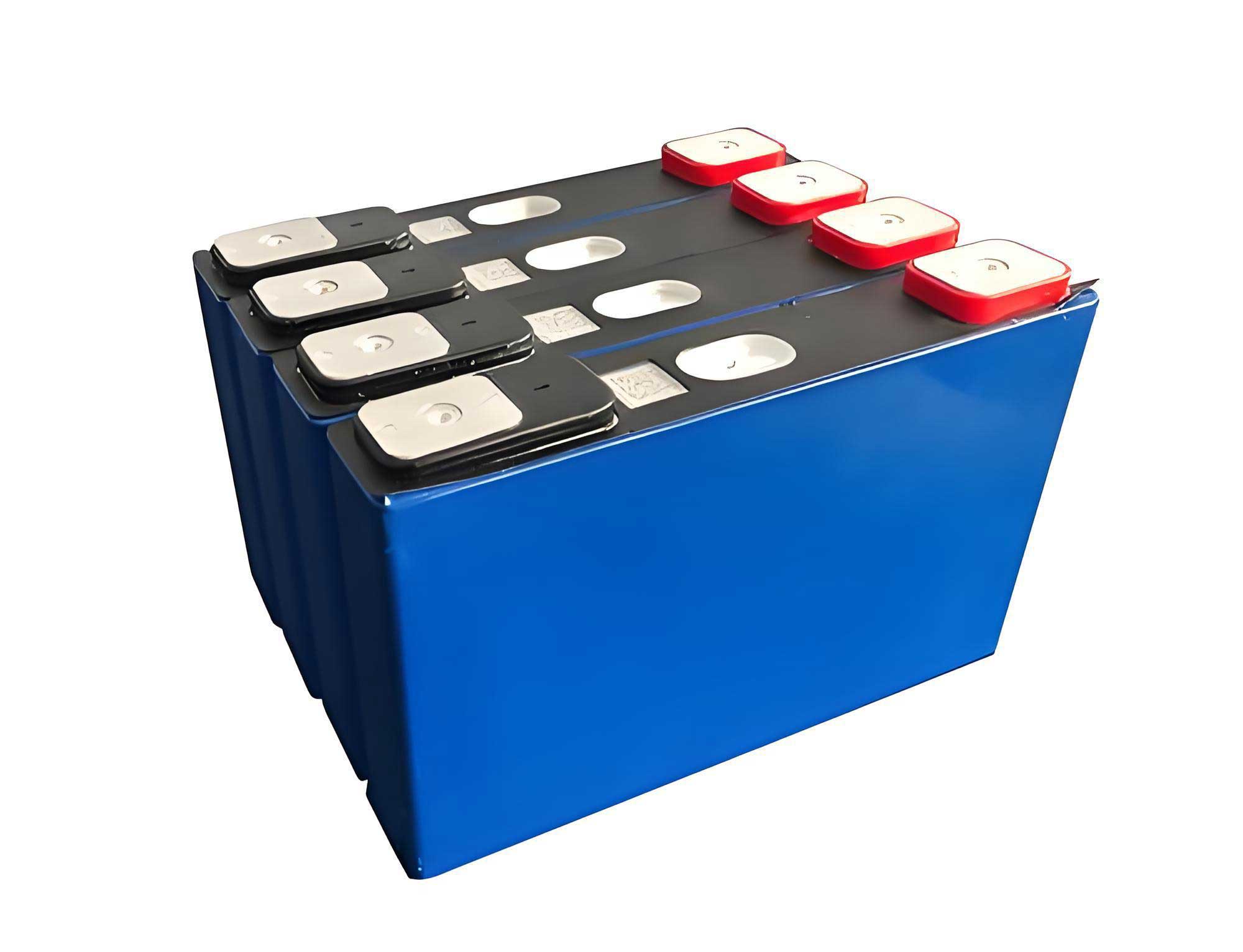
In this investigation, we focus on elucidating the gas generation characteristics of a commercial prismatic LiFePO4 battery under thermal abuse conditions. The core objective is to decompose the thermal runaway process into distinct phenomenological stages, quantify the associated gas yield and composition, and evaluate the resultant explosion hazard. We employ a controlled overheating method using a heating plate within a sealed pressure vessel (constant volume test tank) to simulate a scenario of external heat propagation in a confined environment. This setup allows for the simultaneous tracking of cell temperature, voltage, internal tank pressure, and the detailed analysis of ejected gas species. The findings aim to provide critical data-driven insights for the safety assessment and protection design of LiFePO4 battery-based energy storage installations.
1. Experimental Methodology
1.1 Materials and Apparatus
The test subject was a commercially available prismatic LiFePO4 battery cell with a nominal capacity of 53 Ah and a voltage of 3.3 V at 100% State of Charge (SOC). The experiments were conducted inside a custom-built constant volume test tank, a robust pressure vessel designed to withstand pressures up to 2.0 MPa, with an internal volume of approximately 56.5 liters (calculated from a diameter of 400 mm and depth of 450 mm). Key instrumentation included:
- Data Acquisition System: An Agilent DAQ970A unit recording data at a 1 Hz sampling rate.
- Temperature Measurement: K-type thermocouples attached to the cell surface.
- Pressure Monitoring: A high-accuracy pressure transducer mounted on the tank lid.
- Gas Analysis:
- Off-line: An Agilent 7890B Gas Chromatograph (GC) for detailed compositional analysis of collected gas samples.
- On-line: A portable Fourier Transform Infrared (FTIR) gas analyzer (PROTEA ATMOSFIR, 1 cm⁻¹ resolution) for real-time, time-resolved analysis of gas species evolution during thermal runaway propagation in module-level tests.
- Heating System: A 300 W electric heating plate, controlled by a programmable temperature controller.
1.2 Experimental Setup and Procedure
The experimental configuration aimed to replicate a scenario of conductive heat transfer leading to thermal runaway in a confined space. The LiFePO4 battery cell was placed in direct contact with the heating plate, simulating a condition of thermal propagation from an adjacent failing cell or a hot surface. A metal fixture with a controlled torque of 2 N·m was used to ensure consistent and uniform thermal contact, emulating a mild mechanical constraint. Thermocouples were positioned at the geometric center of the cell surface facing the heater (T1) and the opposite surface (T2). The entire assembly was placed inside the constant volume test tank.
The standard experimental procedure was as follows:
- Tank Preparation: The sealed tank was repeatedly evacuated to below 0.01 atm and refilled with pure nitrogen to atmospheric pressure for three cycles. This process ensured an inert initial atmosphere (primarily N₂), isolating the battery’s internal reactions from external combustion and allowing for accurate measurement of gases generated solely by the LiFePO4 battery decomposition.
- Test Initiation: With data recording active, the heating program was started. Following a common thermal abuse test protocol, the heater temperature was first ramped at 5.5 °C/min to 150 °C and held for 4 hours. If thermal runaway did not occur, the temperature was ramped again at 5.5 °C/min until the cell entered thermal runaway, at which point heating was terminated immediately.
- Data Collection: Cell voltage, surface temperatures (T1, T2), and tank pressure were recorded throughout the process.
- Gas Sampling: After the cell cooled to ambient temperature, the gas mixture inside the tank was homogenized and a representative sample was extracted using a pump into a 0.5 L gas sampling bag.
- Post-Test Analysis: The collected gas sample was analyzed using the Gas Chromatograph to determine the precise composition and concentration of each species.
For time-resolved gas analysis during module-level failure propagation, the FTIR analyzer’s sampling probe was positioned in the exhaust duct of a larger-scale test chamber to continuously monitor the gas stream emitted from a LiFePO4 battery module undergoing thermal runaway.
2. Results and Discussion: Single Cell Behavior
2.1 Thermal and Voltage Response
The evolution of surface temperature and voltage for the 53 Ah LiFePO4 battery under the prescribed heating regime is shown below. The data reveals a characteristic sequence of events leading to full thermal runaway.
During the initial ramp and 150°C hold phase, the cell temperature (T2) increased steadily to approximately 110°C, while the voltage exhibited a gradual, linear decline. The absence of a sudden voltage drop or temperature spike during this prolonged period indicates that the LiFePO4 cathode material itself possesses high thermal stability, and the initial internal reactions (like Solid Electrolyte Interphase – SEI – layer decomposition) are relatively mild. Upon commencing the second heating ramp, the cell temperature continued to rise. At a heater temperature of ~180°C and a cell temperature (T2) of ~112°C, a critical event was observed: the activation of the cell’s safety vent. This “venting” event was marked by a distinct, sharp drop in cell voltage to nearly 0 V and a simultaneous, transient decrease in cell surface temperature by about 10°C. This cooling effect is attributed to the rapid expansion and ejection of high-temperature internal gases (Joule-Thomson effect and heat loss with the ejected mass). Following venting, after a delay of approximately 700 seconds, the cell experienced a full thermal runaway, characterized by a rapid temperature surge to a maximum of about 312°C.
2.2 Pressure Evolution and Gas Generation Phases
The pressure profile inside the constant volume tank provides a direct measure of the total gas generation. Analysis of the pressure and its first derivative (pressure rise rate, dP/dt) allows for a clear demarcation of the gas generation process into three distinct phases, as illustrated in the conceptual figure and described in the table below.
| Phase | Trigger / Description | Key Pressure Features | Calculated Gas Yield (STP) | Dominant Processes |
|---|---|---|---|---|
| I. Venting Gas Release | Opening of the cell safety vent. | Very high initial pressure spike. Peak dP/dt (~9.7 kPa/s). Pressure subsequently relaxes. | ~3.4 L | Release of gases accumulated from early-stage internal decomposition (e.g., electrolyte vapor, SEI breakdown products). Turbulent jetting creates peak overpressure. |
| II. Severe Thermal Runaway Gas Generation | Onset of massive exothermic reactions (cathode/electrolyte, anode/electrolyte). | Sustained, rapid pressure rise. Moderate average dP/dt (~0.42 kPa/s). Major contributor to final pressure. | ~34.4 L | Decomposition of electrolyte, binder, and other cell components fueled by intense internal heat. High-volume gas production from combustion-like reactions. |
| III. Slow Post-Thermal Runaway Gas Generation | Slower reactions and off-gassing after the main exothermic peak. | Slower, prolonged pressure increase. Lowest average dP/dt (~0.01 kPa/s). | ~26.2 L | Continued slow decomposition of residual materials and cooling of the cell carcass. |
The total gas yield from the 53 Ah LiFePO4 battery was calculated by applying the ideal gas law to the final stabilized tank pressure relative to the initial inert pressure. The total free gas volume generated at Standard Temperature and Pressure (STP) conditions was determined to be approximately 64 liters. This substantial volume highlights the explosion risk potential from even a single large-format LiFePO4 battery cell. The pressure rise rate, particularly the extremely high instantaneous value during the initial venting event, serves as a potent early warning signature that could be detected for safety systems.
The gas yield for each phase can be estimated from the stepwise pressure increases. Assuming a constant temperature approximation for simplicity, the ideal gas law relates the pressure change to the volume of gas generated at atmospheric pressure:
$$V_{gas, STP} = \frac{P_{final} – P_{initial}}{P_{atm}} \times V_{tank}$$
Where \(V_{gas, STP}\) is the gas volume at standard conditions, \(P_{final}\) and \(P_{initial}\) are the absolute pressures at the end and start of a phase, \(P_{atm}\) is standard atmospheric pressure (101.325 kPa), and \(V_{tank}\) is the constant volume of the test tank.
2.3 Composition and Hazard of Evolved Gases
GC analysis of the collected gas mixture provides a detailed breakdown of the species generated by the LiFePO4 battery during thermal runaway. The composition is complex, consisting of a variety of light hydrocarbons, hydrogen, carbon oxides, and carbon dioxide. The table below summarizes the primary components and their volumetric percentages.
| Gas Species | Chemical Formula | Volume Percentage (%) | Lower Flammability Limit (LFL) in Air (%) |
|---|---|---|---|
| Hydrogen | H₂ | 56.27 | 4.0 |
| Carbon Dioxide | CO₂ | 22.46 | Non-flammable |
| Carbon Monoxide | CO | 12.00 | 12.5 |
| Ethylene | C₂H₄ | 12.18 | 2.7 |
| Methane | CH₄ | 4.36 | 5.0 |
| Ethane | C₂H₆ | 1.19 | 3.0 |
| Propylene | C₃H₆ | 0.59 | 2.4 |
| Propane | C₃H₈ | 0.30 | 2.1 |
| Butane | C₄H₁₀ | 0.15 | 1.8 |
| Other Hydrocarbons | C₄H₈, C₅H₁₂ | ~0.15 | ~1.5 |
The most striking feature is the dominance of hydrogen (H₂), constituting over 56% of the gas mixture. This is a significant finding for LiFePO4 battery safety, as hydrogen is highly flammable, has a high burning velocity, and a wide flammability range. Carbon monoxide (CO) and light hydrocarbons (especially ethylene C₂H₄ and methane CH₄) are also major combustible components. Carbon dioxide (CO₂) is a primary product of organic material combustion and decomposition but is non-flammable; however, its presence affects the overall explosivity of the mixture.
To assess the explosion hazard, the Lower Flammability Limit (LFL) of the composite gas mixture must be calculated. For a mixture of multiple combustible gases, the LFL can be estimated using Le Chatelier’s principle:
$$LFL_{mix} = \frac{100}{\sum_{i=1}^{n} \frac{y_i}{LFL_i}}$$
Where \(LFL_{mix}\) is the LFL of the mixture (vol%), \(y_i\) is the volume percentage of combustible component \(i\) in the combustible portion of the gas, and \(LFL_i\) is the LFL of component \(i\). However, this standard formula must be adjusted for the presence of significant amounts of inert gas (CO₂ in this case). First, the effective LFL of hydrogen diluted with CO₂ is determined. With CO₂ constituting ~22.5% of the total gas and H₂ constituting ~56.3%, the volume ratio of inert gas (CO₂) to combustible gas (H₂) in this binary pair is approximately 0.4. Consulting standard flammability limit diagrams for H₂-CO₂-air mixtures, the LFL for hydrogen with this level of CO₂ dilution is elevated to approximately 5.5-6.0 vol% in the H₂-CO₂ sub-mixture. Using this adjusted value for the H₂ component and the standard LFLs for other combustibles within the full mixture, the composite LFL of the total LiFePO4 battery thermal runaway gas is calculated to be approximately 4.8 vol% in air.
This value is critically important. It indicates that if the gases from a failing LiFePO4 battery accumulate in a confined space to a concentration exceeding about 4.8% of the air volume, the atmosphere becomes explosible. This LFL is comparable to that of natural gas (methane), underscoring the severe explosion hazard posed by these gases, even from a chemistry generally considered safe like LiFePO4.
3. Results and Discussion: Temporal Evolution of Gas Species
While integrated gas composition is vital for hazard assessment, understanding the temporal sequence of gas release is crucial for developing species-specific early detection strategies. Real-time FTIR analysis conducted during the thermal runaway propagation in a LiFePO4 battery module provided insights into this sequence.
The data revealed that during the initial stages of failure, there is no strict, singular order for the appearance of all gas species. Instead, groups of gases begin to evolve concurrently as soon as significant internal heating and decomposition commence. The earliest detectable gases escaping from the LiFePO4 battery module included carbon monoxide (CO), light hydrocarbons (CH₄, C₂H₄, C₂H₆), and aromatic compounds like xylenes. The detection of hydrocarbons and CO early in the process aligns with the decomposition of the organic electrolyte (e.g., ethylene carbonate, dimethyl carbonate) and the SEI layer. Hydrogen, which dominates the final mixture, was also detected early but its concentration surged dramatically during the peak thermal runaway phase (Phase II), corresponding to more severe decomposition reactions and possible reactions between electrode materials and the electrolyte or breakdown products.
This temporal profile suggests that sensors tuned to detect CO or specific volatile organic compounds (VOCs) could provide the earliest warning of an impending thermal runaway event in a LiFePO4 battery system, potentially before temperatures rise to critical levels or before significant hydrogen is produced.
4. Implications for Safety Engineering
The findings from this study on LiFePO4 battery thermal runaway have direct implications for the design and operation of safe energy storage systems:
- Early Warning Systems: The characteristic signatures—especially the very high initial pressure rise rate during venting and the early emission of CO and hydrocarbons—provide viable detection parameters. Advanced battery management systems (BMS) could integrate pressure sensors and laser-based or electrochemical gas sensors (for CO, VOCs) for pre-thermal runaway warning.
- Ventilation and Gas Management: The large total gas volume (64 L from a 53 Ah cell) mandates robust ventilation design for enclosures. Calculations based on the composite LFL (~4.8%) are essential for determining required ventilation rates to prevent gas accumulation below explosive limits.
- Explosion Protection: In compartments where gas accumulation is possible, explosion-proof equipment, pressure relief panels, or active suppression systems must be considered, given the gas mixture’s methane-like explosibility.
- Firefighting and Emergency Response: Awareness that LiFePO4 battery fires produce large amounts of highly flammable hydrogen and CO is critical. Tactics should consider the risk of gas explosion during suppression activities.
5. Conclusion
This investigation provides a detailed phenomenological and quantitative analysis of the gas generation characteristics during thermal runaway of a commercial prismatic LiFePO4 battery. The process can be delineated into three consecutive phases: Venting Gas Release, Severe Thermal Runaway Gas Generation, and Slow Post-Thermal Runaway Gas Generation. The total gas yield from a single 53 Ah LiFePO4 battery was substantial, approximately 64 liters at STP, with the severe thermal runaway phase being the largest contributor.
The gas mixture is predominantly composed of hydrogen (56.3%), carbon dioxide (22.5%), carbon monoxide (12.0%), and various light hydrocarbons. Despite the non-flammable CO₂ content, the composite Lower Flammability Limit of this mixture is calculated to be about 4.8%, similar to methane, confirming a significant explosion hazard in confined spaces. Real-time analysis indicates that gas emission begins early, with CO, hydrocarbons, and aromatics detectable as initial markers.
These results underscore that while LiFePO4 batteries offer enhanced thermal stability compared to some other chemistries, their thermal runaway is still a high-consequence event accompanied by prolific generation of explosible gases. This work provides essential quantitative data on gas volume, composition, generation rate, and explosibility that is fundamental for advancing the safety science of LiFePO4 battery-based energy storage. This includes informing the development of early fault detection algorithms, designing effective ventilation and gas hazard mitigation systems, and formulating appropriate emergency response protocols, thereby contributing to the safer deployment of large-scale electrochemical energy storage.