
Within the global energy landscape, the significance of electrochemical energy storage is continually growing, bringing with it heightened scrutiny over operational safety. Lithium-ion batteries, particularly LiFePO4 batteries, have emerged as pivotal energy storage units due to their widespread deployment in energy storage power stations. However, the high energy density of battery packs combined with substantial charge and discharge rates readily leads to significant heat accumulation. Should the battery temperature exceed its normal operating window, the risk of thermal runaway escalates, introducing substantial safety hazards. Consequently, liquid cooling thermal management technology, distinguished by its superior heat dissipation capability, is critically important for the energy storage industry and remains a central focus of research in both academic and industrial spheres. This work is dedicated to optimizing the liquid cooling performance for large-capacity LiFePO4 battery energy storage modules, culminating in the design of an efficient, low-energy-consumption liquid cooling plate configuration. Optimization strategies, including the staggered arrangement of cooling plates and differentiated flow velocity distribution, are proposed and subsequently validated through a comprehensive experimental campaign that confirms the system’s excellent performance and reliability.
Cooling Energy Consumption Characteristics of Different Liquid Cooling Channel Designs
During the charge and discharge cycles of a LiFePO4 battery, heat is generated from electrochemical reactions and other factors, causing a rise in temperature and posing a thermal runaway risk. To analyze the energy efficiency of different cooling channel designs, mathematical models for heat generation and thermal conduction within the battery module, as well as a simulation model for the liquid cooling system, were established.
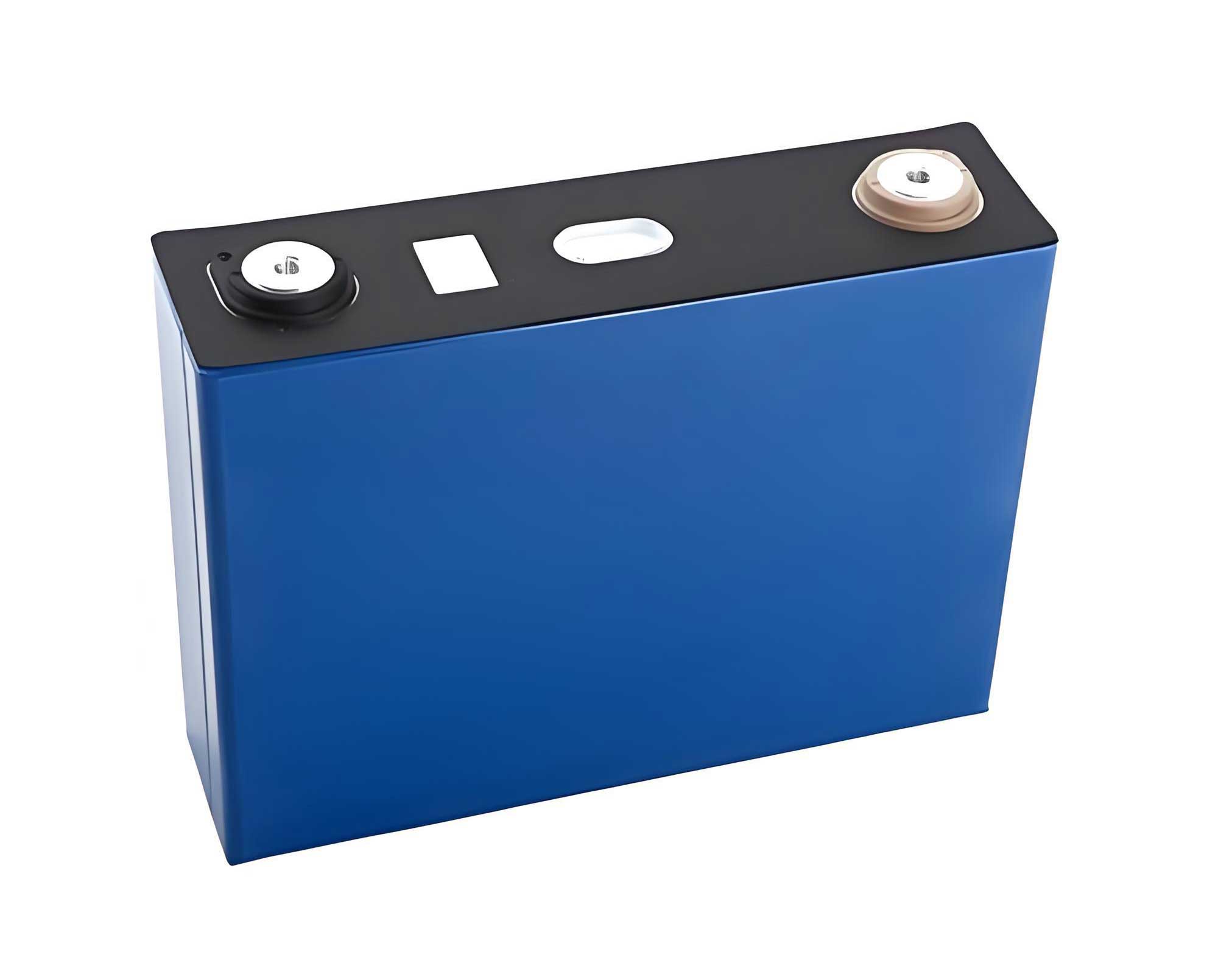
The heat generation rate for a single LiFePO4 cell under a 1C charging rate is a critical parameter. For the 208 Ah LiFePO4 cells studied (dimensions: 170 mm × 200 mm × 50 mm), the heat generation rate was calculated based on the manufacturer’s specifications. A module comprising 30 cells (arranged in 3 columns of 10 cells each with 40 mm spacing) was modeled. The thermal properties of the LiFePO4 battery and the coolant (50% ethylene glycol solution) are summarized below.
| Property | Value |
|---|---|
| Density (kg/m³) | 2405 |
| Specific Heat Capacity (J/kg·K) | 1329 |
| Thermal Conductivity (W/m·K) [X, Z, Y] | 3.72 / 28 / 26 |
| Volumetric Heat Generation Rate @1C (W/m³) | 6362 |
| Parameter | Value |
|---|---|
| Density (kg/m³) | 1070 |
| Specific Heat Capacity (J/kg·K) | 3396 |
| Thermal Conductivity (W/m·K) | 0.399 |
| Dynamic Viscosity (kg/m·s) | 0.00339 |
Three distinct flow channel configurations were designed for the cold plate, as illustrated conceptually below. Scheme 1 employs a traditional serpentine channel. Scheme 2 utilizes a conventional parallel channel design. Scheme 3 introduces a novel hybrid design, termed the Parallel Serpentine channel, which combines a primary parallel structure with auxiliary serpentine features to create an equidistant parallel-folded path.
Computational Fluid Dynamics (CFD) simulations were conducted using ANSYS Fluent to evaluate the cooling performance and pressure drop for each design. The simulations assumed an ambient temperature of 27°C, a 1C charge for 1 hour, and a coolant inlet velocity of 0.1 m/s at 25°C. The key results for maximum temperature ($T_{max}$), temperature difference within the module ($\Delta T_{module}$), and inlet-outlet pressure drop ($\Delta P$) are compared in the following table.
| Channel Structure | $T_{max}$ (°C) | $\Delta T_{module}$ (°C) | $\Delta P$ (Pa) | Relative Pump Energy* |
|---|---|---|---|---|
| Traditional Serpentine | 32.166 | 6.246 | 1252.5 | 100% |
| Traditional Parallel | 32.881 | 7.476 | 101.2 | ~8.1% |
| Parallel Serpentine (Proposed) | 32.610 | 7.077 | 748.6 | ~59.8% |
*Pump energy consumption is proportional to pressure drop at constant flow rate.
The analysis clearly shows the trade-off between cooling performance and energy consumption. While the traditional serpentine channel offers the best temperature control (lowest $T_{max}$ and $\Delta T$), it incurs a very high pressure drop, leading to significant pump energy consumption. The traditional parallel channel minimizes pressure drop but exhibits the poorest cooling performance. The proposed Parallel Serpentine design for the LiFePO4 battery module strikes an effective balance, reducing the pressure drop to approximately 60% of the serpentine design while maintaining cooling performance markedly superior to the simple parallel channel. This makes it a compelling candidate for efficient thermal management.
Development of an Experimental Platform for the Parallel Serpentine Liquid Cooling System
To validate the simulation findings, a physical Parallel Serpentine cold plate was manufactured and integrated into a full-scale battery module to construct a liquid cooling experimental platform.
Cold Plate Design and Fabrication
The cold plate design was finalized using CAD software, with minor adjustments to port locations for manufacturability without compromising thermal performance. The plate was constructed from aluminum alloy for its high thermal conductivity. The manufacturing process involved creating the flow channels in a base plate and then sealing it with a top cover plate using friction stir welding, a robust and reliable method. The final fabricated cold plate is shown in the provided figure.
Experimental Platform Setup
The experimental setup mirrored a commercial energy storage module enclosure. A stainless-steel enclosure (1244 mm × 794 mm × 260 mm) housed the 30-cell LiFePO4 battery module interfaced with four Parallel Serpentine cold plates. Thermocouples were attached to the geometric center of each cell’s front surface in the outer and middle columns (20 sensors total) to capture temperature distribution, particularly the expected maximum temperatures. The system comprised the battery module, a coolant circulation loop with a variable-speed pump and a 25°C chiller, a battery cycler for 1C charging, and a data acquisition system. Thermal interface material (thermal paste) was applied between the cold plates and the LiFePO4 battery cells to minimize contact resistance. A schematic and a photograph of the internal setup confirm the assembly.
Performance Verification of the Parallel Serpentine Liquid Cooling System
Experiments were conducted to benchmark performance and test optimization hypotheses. Cells were preconditioned (discharged, rested at 27°C) before each test.
Baseline: Natural Convection Cooling
Under natural convection (no coolant flow) in a 27°C ambient during a 1C charge, the LiFePO4 battery module temperature rose from 27.1°C to 40.3°C, a $\Delta T$ of 13.2°C. This establishes the high heat load and the critical need for active cooling.
Experiment 1: Effect of Cold Plate Arrangement
With the coolant (0.1 m/s inlet velocity, 25°C), two cold plate arrangements were tested: Symmetric (all inlets on the same side of the module) and Staggered (inlets of adjacent plates on opposite sides).
The results for the outer column of LiFePO4 battery cells, where the temperature gradient is most pronounced in the symmetric case, are shown below. The staggered arrangement successfully reduced the maximum temperature and improved temperature uniformity.
| Battery ID | Max Temp. – Symmetric (°C) | Max Temp. – Staggered (°C) |
|---|---|---|
| 1-1 | 32.6 | 32.7 |
| 1-2 | 33.2 | 33.1 |
| 1-3 | 33.5 | 33.0 |
| 1-4 | 33.7 | 33.6 |
| 1-5 | 33.4 | 33.3 |
| 1-6 | 33.7 | 33.5 |
| 1-7 | 33.2 | 33.6 |
| 1-8 | 33.6 | 33.3 |
| 1-9 | 33.8 | 33.2 |
| 1-10 | 33.8 | 32.9 |
| Column $\Delta T$ | 1.2 | 0.9 |
The overall module performance is summarized in the following table. The maximum temperature consistently occurred in the middle column due to heat accumulation. The staggered arrangement effectively lowered the peak module temperature.
| Configuration | Symmetric Arrangement | Staggered Arrangement |
|---|---|---|
| Outer Column $T_{max}$ | 33.8 °C | 33.6 °C |
| Middle Column $T_{max}$ | 34.6 °C | 34.3 °C |
| Module $T_{max}$ | 34.6 °C | 34.3 °C |
Experiment 2: Effect of Differentiated Coolant Flow Velocity
Using the superior staggered arrangement, two flow strategies were tested at the same total coolant flow rate: Uniform flow (0.2 m/s in all four plates) and Differentiated flow (0.1 m/s in the two outer plates, 0.3 m/s in the two inner plates). This strategy aims to apply higher cooling intensity to the hotter core of the LiFePO4 battery module.
Temperature data for the critical middle column is presented below. The differentiated flow yielded lower temperatures for most cells.
| Battery ID | Max Temp. – Uniform 0.2 m/s (°C) | Max Temp. – Differentiated Flow (°C) |
|---|---|---|
| 2-1 | 32.2 | 32.0 |
| 2-2 | 32.6 | 32.3 |
| 2-3 | 32.3 | 32.5 |
| 2-4 | 32.6 | 32.5 |
| 2-5 | 32.9 | 32.6 |
| 2-6 | 32.8 | 32.7 |
| 2-7 | 32.8 | 32.7 |
| 2-8 | 32.7 | 32.4 |
| 2-9 | 32.4 | 32.5 |
| 2-10 | 32.3 | 32.2 |
The impact on the overall module maximum temperature across all tested conditions is consolidated below. The optimized system (staggered plates + differentiated flow) achieves a remarkable temperature control performance.
| Cooling Condition | Module $T_{max}$ (°C) | Reduction from Natural Convection |
|---|---|---|
| Natural Convection (Baseline) | 40.3 | – |
| Liquid Cooling (Symmetric, 0.1 m/s Uniform) | 34.6 | 5.7 °C |
| Liquid Cooling (Staggered, 0.1 m/s Uniform) | 34.3 | 6.0 °C |
| Liquid Cooling (Staggered, 0.2 m/s Uniform) | 32.9 | 7.4 °C |
| Liquid Cooling (Staggered, Differentiated Flow) | 32.7 | 7.6 °C |
Error Analysis and Discussion
A comparison between experimental and simulation maximum temperatures revealed discrepancies. The largest absolute error was 1.94°C (5.6% error rate) for the symmetric arrangement test, and the smallest was 1.42°C (4.3%) for the uniform 0.2 m/s test. These errors are within an acceptable range for engineering studies and validate the simulation model’s overall accuracy. Potential sources include simplifications in the battery’s internal heat generation and material property models, manufacturing tolerances in the cold plate flow channels, experimental environmental factors (enclosure sealing, pump perturbations), and thermal contact resistance between the cold plate and the LiFePO4 battery surface, which is challenging to eliminate completely in practice.
Conclusion
This work focused on the thermal management of a large-capacity energy storage module composed of 30 LiFePO4 battery cells. A novel Parallel Serpentine flow channel design for liquid cooling plates was proposed and analyzed through simulation, demonstrating an optimal balance between cooling performance and pump energy consumption. An experimental platform was successfully built to validate the design. The results confirmed that the liquid cooling system effectively controlled the module’s maximum temperature during 1C charging in a 27°C environment, reducing it from 40.3°C under natural convection to 32.7°C. Furthermore, the proposed optimizations—staggered cold plate arrangement and differentiated coolant flow velocity—were experimentally proven to enhance cooling performance further, lowering the maximum temperature by an additional 0.3°C and 0.2°C, respectively. These temperatures are well within the safe operating range for LiFePO4 batteries. The close agreement between simulation and experiment (error < 6%) confirms the reliability of the models and the efficacy of the optimized Parallel Serpentine liquid cooling system for LiFePO4 battery energy storage applications.