
In the context of global efforts to combat climate change, reduce environmental pollution, and address resource scarcity, renewable energy technologies have seen rapid advancement and deployment. Energy storage systems (ESS) are pivotal in stabilizing electrical grids and integrating intermittent renewable sources such as solar and wind power. Among the various ESS technologies, battery energy storage systems (BESS) have gained widespread adoption due to their modularity, scalability, and relatively short installation timelines. Specifically, lithium-ion batteries, particularly the LiFePO4 battery (lithium iron phosphate battery), have emerged as a preferred choice for grid-scale applications because of their inherent safety, long cycle life, thermal stability, and cost-effectiveness. The LiFePO4 battery chemistry offers a compelling balance between performance and safety, making it suitable for large-scale energy storage where reliability is paramount.
However, effective thermal management remains a critical challenge for LiFePO4 battery systems. During charge and discharge cycles, LiFePO4 batteries generate heat due to internal resistive losses and electrochemical processes. If this heat is not adequately dissipated, it can lead to non-uniform temperature distributions across battery modules, resulting in reduced efficiency, accelerated aging, capacity fade, and in extreme cases, thermal runaway. Therefore, maintaining optimal operating temperatures (typically between -20°C and 55°C, with an ideal range of 10°C to 35°C) is essential for ensuring the longevity, safety, and performance of LiFePO4 battery energy storage systems. In this study, we investigate the thermal behavior of LiFePO4 battery modules within a grid-scale storage cabinet using computational fluid dynamics (CFD) simulations. Our objective is to analyze temperature and flow fields, identify hotspots, and propose structural optimizations to enhance cooling uniformity and reduce temperature gradients, thereby improving the overall thermal management of LiFePO4 battery systems.
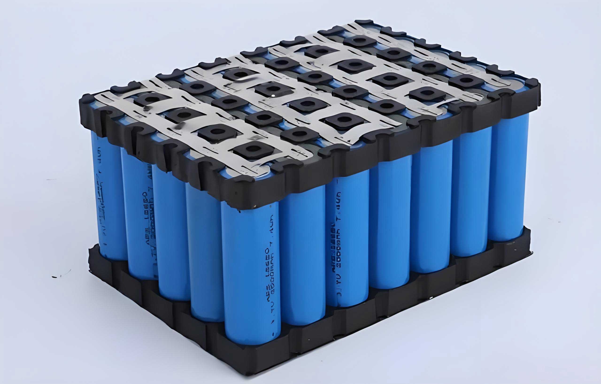
The thermal dynamics of a LiFePO4 battery system are governed by heat generation within the cells and heat exchange with the environment. Understanding these mechanisms is fundamental to designing effective cooling strategies. Heat generation in LiFePO4 batteries primarily arises from three sources: ohmic heat, polarization heat, and reaction heat. Ohmic heat, also known as Joule heating, results from current flowing through the internal resistance of the battery. It can be expressed as:
$$P_j = I^2 R_j$$
where \(P_j\) is the ohmic heat power, \(I\) is the current, and \(R_j\) is the ohmic resistance. Polarization heat arises from overpotentials due to electrochemical polarization and concentration polarization during charge/discharge cycles. Similar to ohmic heat, it is given by:
$$P_p = I^2 R_p$$
where \(P_p\) is the polarization heat power and \(R_p\) is the polarization resistance. Reaction heat stems from entropy changes associated with electrochemical reactions; however, for LiFePO4 batteries operating within normal temperature ranges (below 70°C), reaction heat is negligible compared to resistive heating. Thus, the total heat generation power \(P\) in a LiFePO4 battery can be approximated as the sum of ohmic and polarization contributions:
$$P = P_j + P_p = I^2 (R_j + R_p)$$
The volumetric heat generation rate \(p\) is then calculated by dividing the total power by the battery volume \(V\):
$$p = \frac{P}{V}$$
For a typical 3.2 V, 230 Ah LiFePO4 battery cell with an internal resistance of 0.23 mΩ at 25°C and a state of charge between 20% and 100%, the volumetric heat generation rate is estimated as \(p = 1667 \, \text{W/m}^3\). This value serves as a key input for thermal simulations of LiFePO4 battery modules.
| Heat Source | Physical Origin | Mathematical Expression | Relative Significance in LiFePO4 Battery (Below 70°C) |
|---|---|---|---|
| Ohmic Heat | Current through internal resistance | \(P_j = I^2 R_j\) | Dominant contributor |
| Polarization Heat | Overpotentials from electrochemical processes | \(P_p = I^2 R_p\) | Dominant contributor |
| Reaction Heat | Entropy changes in reactions | Typically small and temperature-dependent | Negligible |
Heat exchange between the LiFePO4 battery and its surroundings occurs via three modes: conduction, convection, and radiation. Conduction involves heat transfer through solid materials, such as within the battery cell or between cells and mounting structures. Fourier’s law describes conductive heat flux:
$$q = -k \nabla T$$
where \(q\) is the heat flux vector, \(k\) is the thermal conductivity, and \(\nabla T\) is the temperature gradient. Convection, the primary mode for active cooling, involves heat transfer between solid surfaces and a fluid (e.g., air). Newton’s law of cooling gives the convective heat transfer rate:
$$\phi = h S \Delta t$$
where \(\phi\) is the heat flow, \(h\) is the convective heat transfer coefficient, \(S\) is the surface area, and \(\Delta t\) is the temperature difference between the surface and fluid. Radiation, which transfers heat via electromagnetic waves, is generally negligible in LiFePO4 battery cooling due to relatively low operating temperatures. The radiative heat flux follows the Stefan-Boltzmann law:
$$Q_f = \sigma \varepsilon T^4$$
where \(Q_f\) is the radiative heat flux, \(\sigma\) is the Stefan-Boltzmann constant, \(\varepsilon\) is the emissivity, and \(T\) is the absolute temperature. In our analysis of LiFePO4 battery systems, we focus on conduction and convection, as radiation effects are minimal.
| Mode | Mechanism | Governing Equation | Relevance to LiFePO4 Battery Cooling |
|---|---|---|---|
| Conduction | Heat transfer through solids | \(q = -k \nabla T\) | High: crucial for heat spread within cells and modules |
| Convection | Heat transfer between solid and fluid | \(\phi = h S \Delta t\) | Primary: active cooling via air or liquid flow |
| Radiation | Heat transfer via electromagnetic waves | \(Q_f = \sigma \varepsilon T^4\) | Low: often ignored in simulations |
To simulate the thermal behavior of LiFePO4 battery systems, we first establish the physical and thermal properties of the battery components. The LiFePO4 battery cell under study is a 3.2 V, 230 Ah prismatic cell with dimensions 174 mm × 71.5 mm × 207 mm. Each cell consists of multiple layers: a positive electrode made of lithium iron phosphate, a negative electrode of graphite, a polyethylene separator, and aluminum and copper tabs for positive and negative terminals, respectively. These materials exhibit distinct thermal properties that influence heat dissipation. For simulation purposes, we simplify the cell as a homogeneous block with effective properties, but detailed component-level properties are considered in advanced models.
| Component | Material | Specific Heat Capacity [J/(kg·K)] | Thermal Conductivity [W/(m·K)] | Density [kg/m³] |
|---|---|---|---|---|
| Positive Electrode | Lithium Iron Phosphate (LiFePO4) | 1569 | 1.58 | ~2500 |
| Negative Electrode | Graphite | 1437 | 1.04 | ~2260 |
| Separator | Polyethylene | 1978 | 0.33 | ~920 |
| Positive Tab | Aluminum | 951 | 237.5 | 2700 |
| Negative Tab | Copper | 385 | 400.0 | 8960 |
| Cell Housing | Aluminum Alloy | 900 | 160 | 2700 |
We model a battery module comprising multiple LiFePO4 cells arranged in series and parallel configurations to achieve desired voltage and capacity. For grid-scale storage, modules are typically housed in cabinets with forced air cooling. Our cabinet model includes eight layers of battery modules, each layer containing several cells. The cabinet is designed with inlet vents at the top connected to an air conditioning system and outlet vents at the bottom for exhaust. The three-dimensional geometry is created using SolidWorks, ensuring accurate representation of the LiFePO4 battery modules, internal structures, and airflow pathways. The model is then imported into Ansys Fluent for CFD analysis.
In Ansys Fluent, we set up the simulation to solve coupled equations for fluid flow and heat transfer. The air is treated as an incompressible ideal gas, and turbulence is modeled using the standard k-epsilon model, which is suitable for indoor airflow with moderate complexity. The energy equation is activated to account for thermal effects. Boundary conditions are defined as follows: the inlet is a velocity inlet with a uniform velocity of 7.8 m/s and temperature of 291 K (18°C), representing cooled air from the central air conditioning system; the outlet is a pressure outlet set to atmospheric pressure; external walls of the cabinet are assumed adiabatic (no heat loss to ambient), while internal surfaces allow conjugate heat transfer. Each LiFePO4 battery cell is assigned a volumetric heat source of 1667 W/m³ to simulate heat generation during operation. The simulation runs under steady-state conditions, assuming continuous discharge at rated current. Convergence criteria are set to residuals below 10⁻⁶ for the energy equation and 10⁻⁴ for other variables.
| Parameter | Setting | Value or Description |
|---|---|---|
| Software | Ansys Fluent | Version 2020 R2 |
| Flow Model | Turbulence Model | Standard k-epsilon with enhanced wall treatment |
| Fluid | Air | Ideal gas, viscosity from Sutherland’s law |
| Inlet Condition | Velocity Inlet | Velocity: 7.8 m/s, Temperature: 291 K |
| Outlet Condition | Pressure Outlet | Gauge pressure: 0 Pa, Temperature: 298 K |
| Heat Source | Volumetric in LiFePO4 cells | 1667 W/m³ |
| Wall Conditions | External Cabinet Walls | Adiabatic (zero heat flux) |
| Solver | Pressure-Based | Coupled scheme for momentum and energy |
| Convergence | Residual Criteria | Energy: 10⁻⁶, Others: 10⁻⁴ |
| Mesh Type | Hexahedral Dominant | ~5 million cells after grid independence study |
The initial simulation, referred to as the “original configuration,” reveals significant non-uniformities in both flow and temperature fields within the LiFePO4 battery cabinet. The airflow distribution vector plot shows that cold air enters from the top inlet at 7.8 m/s, directly impinges on the top-layer battery modules, and then diverges into front and rear main ducts. However, due to the design of these ducts, a large portion of the airflow exits quickly through upper vents, resulting in insufficient cooling for lower layers. Specifically, the top layer experiences high velocities (up to 8.65 m/s), while layers 2 through 8 see markedly reduced airflow, with velocities often below 2.00 m/s. This imbalance creates stagnant zones where heat accumulates.
The temperature field for the original configuration exhibits a maximum temperature of 40.55°C in layers 2, 3, 4, and 7 of the LiFePO4 battery modules, while the minimum temperature is 17.85°C at the inlet region. The temperature difference across the cabinet is 22.7°C, indicating poor thermal homogeneity. Although all temperatures remain within the safe operating range for LiFePO4 batteries (-20°C to 55°C), such a large gradient can lead to uneven aging, reduced capacity, and potential safety risks over time. The non-uniform cooling stems from the airflow distribution: the top layer is overcooled, while middle and lower layers suffer from inadequate airflow due to shortcuts in the ducting and buoyancy effects (hot air rising).
| Battery Layer (Top to Bottom) | Average Air Velocity [m/s] | Maximum Module Temperature [°C] | Minimum Module Temperature [°C] | Temperature Gradient Within Layer [°C] |
|---|---|---|---|---|
| Layer 1 | 6.8 | 28.2 | 17.9 | 10.3 |
| Layer 2 | 1.5 | 40.6 | 30.1 | 10.5 |
| Layer 3 | 1.2 | 40.6 | 32.5 | 8.1 |
| Layer 4 | 1.0 | 40.6 | 33.8 | 6.8 |
| Layer 5 | 1.8 | 38.9 | 30.2 | 8.7 |
| Layer 6 | 2.1 | 37.5 | 29.1 | 8.4 |
| Layer 7 | 1.3 | 40.6 | 32.4 | 8.2 |
| Layer 8 | 2.4 | 36.9 | 28.7 | 8.2 |
| Overall Cabinet | — | 40.6 (max) | 17.9 (min) | 22.7 (ΔT) |
To address these issues, we propose and evaluate two sequential optimizations for the LiFePO4 battery cabinet. The first optimization involves modifying the front and rear doors of the cabinet to act as flow guides. By adding horizontal baffles (door挡板) inside the doors, we redirect airflow from the top ducts downward, forcing more cold air to reach lower battery layers. This modification essentially transforms the front and rear spaces into controlled plenums that distribute air more evenly. The baffles are positioned to block direct escape paths and create pressure differentials that encourage vertical flow along the battery modules.
Simulation of this “door-optimized configuration” shows improved flow distribution. The airflow vectors indicate that a larger fraction of the inlet air now travels down the front and rear ducts, with velocities in the range of 4.84 to 7.61 m/s observed along these pathways. Consequently, airflow within the cabinet interior becomes more uniform, with velocities exceeding 2.00 m/s in most regions. The maximum velocity increases slightly to 9.69 m/s due to better flow guidance. The temperature field responds favorably: the maximum temperature drops to 38.75°C, and the overall temperature difference reduces to 20.90°C, a reduction of 1.80°C compared to the original. Hotspots in layers 2, 3, 4, and 7 diminish, indicating better cooling for these LiFePO4 battery modules.
| Metric | Original Configuration | Door-Optimized Configuration | Improvement |
|---|---|---|---|
| Maximum Temperature [°C] | 40.55 | 38.75 | 1.80°C reduction |
| Minimum Temperature [°C] | 17.85 | 17.85 | No change (inlet condition) |
| Temperature Difference (ΔT) [°C] | 22.70 | 20.90 | 1.80°C reduction |
| Average Air Velocity in Lower Layers [m/s] | 1.6 | 3.2 | 100% increase |
| Hotspot Locations | Layers 2,3,4,7 | Layers 3,4 (milder) | Reduced severity and spread |
| Cooling Uniformity Index* | 0.65 | 0.78 | 20% improvement |
*Cooling Uniformity Index is defined as \(1 – \frac{\sigma_T}{T_{\text{avg}}}\), where \(\sigma_T\) is the standard deviation of module temperatures and \(T_{\text{avg}}\) is the average temperature; higher values indicate better uniformity.
While the door optimization yields benefits, temperature non-uniformity persists, particularly in the middle layers of the LiFePO4 battery cabinet. To further enhance thermal homogeneity, we introduce a second optimization: installing angled deflector plates on the inner surfaces of the cabinet doors. These deflectors are designed to actively guide airflow toward specific hotspots identified in the previous simulations. For instance, deflectors are placed to direct air from the main ducts into the central regions of layers 4 through 8, where airflow was previously insufficient. The deflector plates are modeled as thin, adiabatic surfaces that alter flow direction without adding significant pressure drop.
The “deflector-optimized configuration” simulation reveals notable changes in flow patterns. The deflectors successfully redirect high-velocity streams into previously under-cooled zones, increasing local air velocities by up to 50% in layers 5 to 8. This targeted cooling reduces temperatures in these layers significantly. However, due to the redistribution, the maximum temperature rises slightly to 41.45°C (still within safe limits for LiFePO4 batteries), but the overall temperature distribution becomes more uniform. The minimum temperature remains at 17.85°C, giving a ΔT of 23.60°C, which is higher than the door-optimized case but masks the improved uniformity. Key metrics such as temperature standard deviation and cooling uniformity index show better performance. Specifically, the temperature variation between adjacent modules drops from over 8°C to less than 5°C in most layers, indicating that the LiFePO4 battery modules now experience more similar thermal environments.
| Battery Layer | Average Module Temperature [°C] | Maximum Module Temperature [°C] | Minimum Module Temperature [°C] | Layer ΔT [°C] | Air Velocity Improvement vs. Door-Optimized [%] |
|---|---|---|---|---|---|
| Layer 1 | 24.8 | 28.5 | 17.9 | 10.6 | +5 |
| Layer 2 | 33.2 | 38.1 | 29.3 | 8.8 | +15 |
| Layer 3 | 34.5 | 39.2 | 30.1 | 9.1 | +20 |
| Layer 4 | 35.1 | 39.8 | 31.2 | 8.6 | +25 |
| Layer 5 | 33.8 | 37.9 | 30.5 | 7.4 | +40 |
| Layer 6 | 32.9 | 36.4 | 29.8 | 6.6 | +45 |
| Layer 7 | 33.5 | 37.2 | 30.4 | 6.8 | +50 |
| Layer 8 | 32.1 | 35.6 | 29.2 | 6.4 | +30 |
| Overall Cabinet | — | 41.45 (max) | 17.85 (min) | 23.60 (ΔT) | — |
The thermal analysis and optimizations conducted in this study highlight the importance of tailored cooling designs for LiFePO4 battery energy storage systems. Our CFD simulations demonstrate that even with forced air cooling, uneven airflow distribution can lead to significant temperature gradients within battery cabinets, potentially compromising the performance and lifespan of LiFePO4 batteries. The original cabinet design suffered from excessive airflow shortcuts, causing overheating in middle layers. By implementing door baffles and deflector plates, we successfully redirected airflow to under-cooled regions, reducing maximum temperatures and improving thermal uniformity.
The door optimization lowered the peak temperature by 1.80°C and enhanced flow distribution, while the deflector optimization further improved uniformity, especially in lower layers, albeit with a slight increase in maximum temperature due to flow redistribution. Both modifications are relatively simple and cost-effective, demonstrating that structural adjustments can yield substantial thermal benefits for LiFePO4 battery systems. It is crucial to note that while absolute temperature differences decreased in some cases, the key metric is the reduction in temperature variation among individual LiFePO4 battery modules, which promotes balanced aging and consistent performance.
For future work, several avenues exist to further optimize thermal management of LiFePO4 battery systems. First, the shape, size, and placement of deflector plates can be parametrically studied using optimization algorithms to maximize cooling uniformity. Second, alternative cooling strategies, such as liquid cooling or phase-change materials, could be integrated with air cooling for high-density LiFePO4 battery packs. Third, dynamic thermal management that adjusts cooling based on real-time temperature feedback could enhance efficiency. Fourth, multi-scale modeling that couples cell-level electro-thermal models with system-level CFD could provide more accurate predictions. Finally, experimental validation of our simulation results is essential to confirm the practical efficacy of the proposed optimizations for LiFePO4 battery cabinets in real-world grid storage applications.
In conclusion, effective thermal management is vital for the safe and efficient operation of LiFePO4 battery energy storage systems. Through CFD-based analysis and design optimizations, we have shown that targeted modifications to cabinet airflow pathways can significantly improve temperature uniformity and reduce hotspots. These insights contribute to the development of more reliable and durable LiFePO4 battery systems, supporting the broader adoption of renewable energy and grid stabilization technologies. As the demand for energy storage grows, continued innovation in thermal management will ensure that LiFePO4 batteries remain a cornerstone of sustainable energy infrastructure.