
In the realm of electric vehicles, the thermal management of battery systems is paramount to ensure safety, longevity, and optimal performance. Among various battery chemistries, the LiFePO4 battery stands out due to its high energy density, long cycle life, and low self-discharge rate. However, during high-rate discharge processes, excessive heat generation can lead to temperature rise, potentially exceeding safe operational limits. This necessitates efficient cooling strategies. In this study, I employ a numerical approach to explore liquid cooling solutions for LiFePO4 battery packs, focusing on the design of cold plates with serpentine channels. Through electrochemical-thermal coupling modeling and multiphysics simulations, I analyze the impacts of coolant inlet temperature, flow velocity, and channel cross-sectional shape on cooling efficiency. The goal is to provide a foundational research basis for optimizing battery thermal management systems.
The foundation of this investigation lies in the development of a robust electrochemical-thermal coupling model for a single LiFePO4 battery cell. This model integrates mass conservation, electrochemical kinetics, charge conservation, and energy conservation principles. For a typical 38120 LiFePO4 battery with a capacity of 10 Ah and nominal voltage of 3.2 V, the positive electrode active material is LiFePO4, and the negative electrode is graphite (C6), with aluminum and copper as current collectors. The coupling mechanism involves the electrochemical model computing heat generation $Q_h$ during discharge, which is fed into the thermal model. The thermal model then calculates heat exchange with the environment and feeds back the average battery temperature to the electrochemical model. The heat generation rate can be expressed as:
$$ Q_h = I \left( V_{ocv} – V \right) – I T \frac{\partial V_{ocv}}{\partial T} $$
where $I$ is the current, $V_{ocv}$ is the open-circuit voltage, $V$ is the terminal voltage, and $T$ is temperature. This equation accounts for irreversible and reversible heat effects. To validate the model, simulations were conducted at discharge rates of 0.3C, 0.5C, 1C, and 2C under an ambient temperature of 298.15 K. The simulated surface average temperatures were compared with experimental data from literature. As shown in Table 1, the results demonstrate strong agreement, with a maximum deviation of 0.737 K at 2C discharge, validating the model’s reliability for subsequent analyses.
| Discharge Rate | Simulated Max Temp (K) | Experimental Max Temp (K) | Deviation (K) |
|---|---|---|---|
| 0.3C | 298.45 | 298.40 | 0.05 |
| 0.5C | 299.12 | 299.00 | 0.12 |
| 1C | 301.78 | 301.50 | 0.28 |
| 2C | 308.92 | 308.18 | 0.74 |
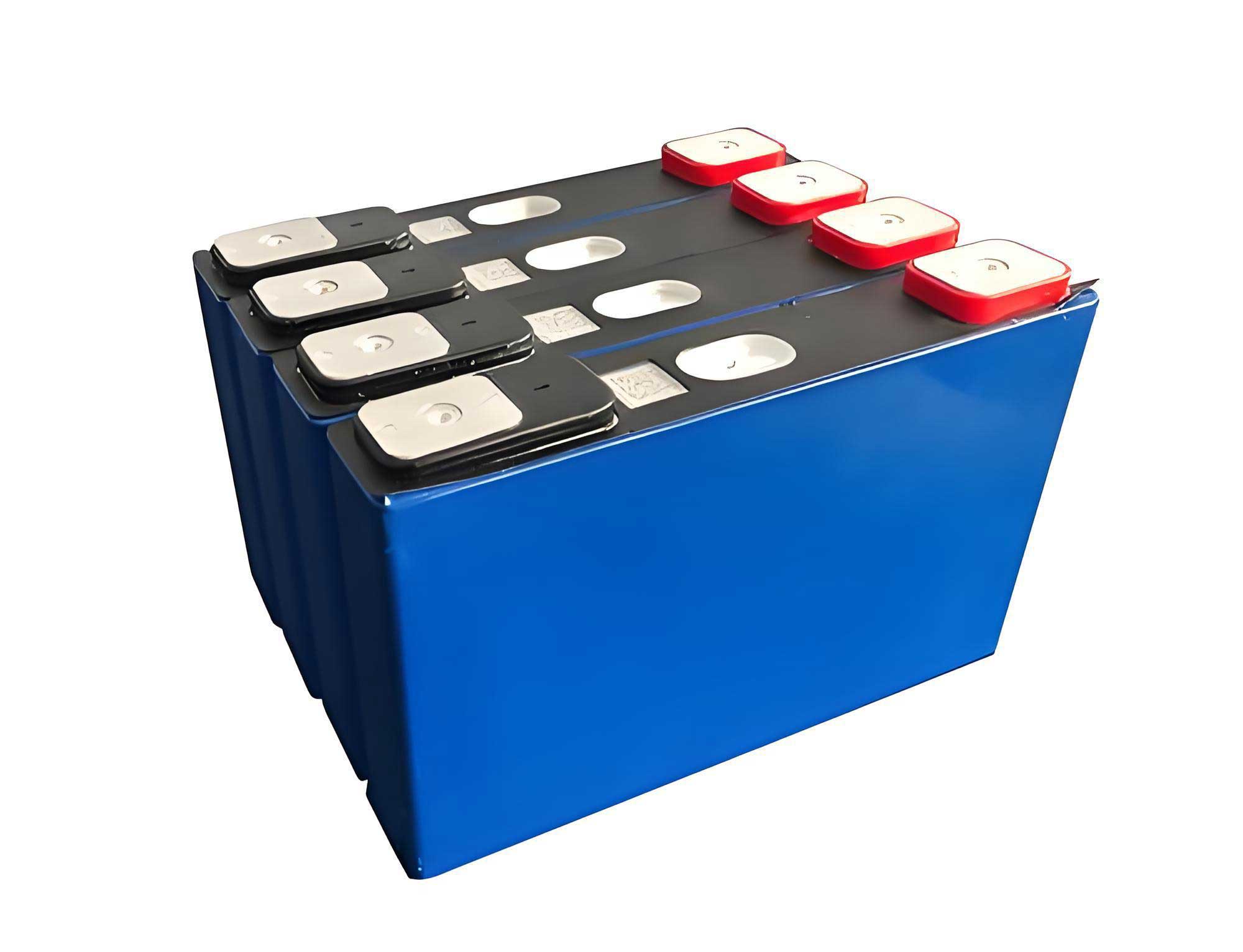
Following validation, I constructed a physical model for a battery pack comprising six 38120 LiFePO4 battery cells and an aluminum cold plate with a serpentine channel. The cold plate dimensions are 256 mm in length, 46 mm in width, and 5 mm in height. A 2-mm layer of thermal conductive silicone gel, with a thermal conductivity of 2.7 W/(m·K), is applied between the batteries and the cold plate to enhance heat transfer. The coolant is water, and the channel has a rectangular cross-section with initial dimensions of 3 mm × 5 mm. The boundary conditions are set for a 2C discharge rate, ambient temperature of 298.15 K, and external heat transfer coefficient of 1 W/(K·m²). The inlet coolant temperature is 298.15 K, and the inlet velocity is 0.1 m/s, corresponding to a Reynolds number of 487, justifying the use of a laminar flow model. Grid independence was verified by comparing maximum battery pack temperatures across different mesh sizes, as summarized in Table 2, confirming that results are mesh-independent beyond 309,628 elements.
| Mesh Elements | Max Battery Pack Temp (K) | Deviation from Previous (%) |
|---|---|---|
| 97,813 | 308.92 | – |
| 154,229 | 308.95 | 0.01 |
| 219,476 | 308.98 | 0.01 |
| 309,628 | 309.01 | 0.01 |
Simulation results under baseline conditions reveal a maximum battery pack temperature of 308.92 K and a maximum temperature difference within the pack of 4.04 K. The coolant temperature rise along the channel is 3.06 K. To optimize cooling, I systematically varied parameters. First, the effect of coolant inlet temperature was analyzed by keeping the inlet velocity at 0.1 m/s and channel cross-section constant. As inlet temperature increased from 298.15 K to 308.15 K, the maximum pack temperature rose linearly, while the temperature difference decreased slightly. This is captured in Table 3, showing that inlet temperatures above 306.15 K lead to maximum temperatures exceeding 313 K, which may compromise the LiFePO4 battery performance and safety.
| Inlet Temp (K) | Max Pack Temp (K) | Max Temp Difference (K) | Coolant Temp Rise (K) |
|---|---|---|---|
| 298.15 | 308.92 | 4.04 | 3.06 |
| 300.15 | 310.45 | 3.78 | 3.12 |
| 302.15 | 311.98 | 3.52 | 3.18 |
| 304.15 | 313.51 | 3.26 | 3.24 |
| 306.15 | 315.04 | 3.00 | 3.30 |
| 308.15 | 316.57 | 2.74 | 3.36 |
Next, I investigated the influence of coolant inlet velocity by fixing the inlet temperature at 298.15 K. The velocity was varied from 0.05 m/s to 0.25 m/s. The results, presented in Table 4, indicate that higher velocities reduce the maximum pack temperature but exhibit diminishing returns beyond 0.2 m/s. The temperature difference initially increases then decreases, suggesting an optimal range for uniform cooling. The relationship between cooling effectiveness and velocity can be approximated by:
$$ \Delta T_{\text{max}} \propto \frac{1}{v^{0.5}} $$
where $\Delta T_{\text{max}}$ is the maximum temperature rise and $v$ is the inlet velocity. This highlights the trade-off between pumping power and thermal performance for the LiFePO4 battery pack.
| Inlet Velocity (m/s) | Max Pack Temp (K) | Max Temp Difference (K) | Coolant Temp Rise (K) |
|---|---|---|---|
| 0.05 | 312.34 | 4.01 | 6.12 |
| 0.10 | 308.92 | 4.04 | 3.06 |
| 0.15 | 307.23 | 4.02 | 2.04 |
| 0.20 | 306.31 | 3.99 | 1.53 |
| 0.25 | 305.78 | 3.96 | 1.22 |
Finally, the impact of channel cross-sectional shape was explored under two scenarios: constant inlet velocity and constant flow rate. For constant inlet velocity of 0.1 m/s, the channel width was fixed at 3 mm, while the height varied from 3 mm to 7 mm. The data in Table 5 shows that larger cross-sections lower the maximum pack temperature, but the improvement plateaus beyond 6 mm height. For constant flow rate of $1.5 \times 10^{-6}$ m³/s, the cooling efficiency initially worsens then improves with increasing height, with the best performance at 7 mm. The heat transfer coefficient $h$ for the channel can be estimated using:
$$ h = \frac{Nu \cdot k}{D_h} $$
where $Nu$ is the Nusselt number, $k$ is thermal conductivity, and $D_h$ is hydraulic diameter given by $D_h = \frac{2ab}{a+b}$ for a rectangle of height $a$ and width $b$. This explains why larger cross-sections enhance cooling but with diminishing gains, crucial for designing compact systems for LiFePO4 battery packs.
| Cross-Section (mm²) | Constant Velocity (0.1 m/s) Max Temp (K) | Constant Flow Rate Max Temp (K) | Hydraulic Diameter (mm) |
|---|---|---|---|
| 3×3 | 309.85 | 308.50 | 3.00 |
| 3×4 | 309.25 | 308.94 | 3.43 |
| 3×5 | 308.92 | 308.80 | 3.75 |
| 3×6 | 308.65 | 308.60 | 4.00 |
| 3×7 | 308.50 | 308.45 | 4.20 |
In conclusion, this numerical study provides comprehensive insights into liquid cooling schemes for LiFePO4 battery packs. Key findings indicate that lower coolant inlet temperatures and higher inlet velocities generally improve cooling, but practical limits exist due to energy consumption and system constraints. For the LiFePO4 battery pack, an inlet temperature below 306.15 K is recommended to maintain temperatures under 313 K. In terms of velocity, values around 0.2 m/s offer a balance between performance and power draw. Regarding channel design, a cross-section of 3 mm × 6 mm under constant velocity or 3 mm × 7 mm under constant flow rate yields optimal cooling efficiency. These results underscore the importance of tailored thermal management strategies to ensure the safe and efficient operation of LiFePO4 battery systems in electric vehicles. Future work could explore advanced coolants, multi-objective optimization, and transient analyses to further enhance LiFePO4 battery thermal management.