
As a lead engineer involved in the innovation of oilfield equipment, I have dedicated significant effort to overcoming the limitations of traditional diesel-powered workover rigs. These conventional rigs, while robust, suffer from high能耗, noise pollution, and substantial emissions of greenhouse gases. The shift towards electric workover rigs promises a cleaner alternative, but practical implementation has been hindered by inadequate wellsite power infrastructure. Typical wellsite transformers, rated at 75 kVA/400 V, cannot supply sufficient power for efficient operations, resulting in slow hoisting speeds and poor解卡 capability. High-voltage grid connections (10 kV/6 kV) require cumbersome mobile substations and pose safety risks, leading to prolonged downtime. Therefore, the integration of energy storage systems based on LiFePO4 batteries emerges as a transformative solution. The LiFePO4 battery, with its high energy density, long cycle life, and excellent safety profile, enables修井机 to operate independently of grid constraints while offering rapid charge-discharge cycles. This article delves into the design, implementation, and validation of a LiFePO4 battery-based energy storage system for workover rigs, highlighting its technical advantages and field performance.
The overall design requirements for the energy storage system are centered on reliability, efficiency, and adaptability to harsh oilfield environments. The system comprises several key components: PACK battery modules, a Battery Management System (BMS), a charge-discharge management system, and a thermal management system. The PACK modules output high-voltage direct current (DC), which is inverted to 380 V alternating current (AC) via a frequency converter to drive the electric winch and auxiliary wellsite equipment. Specifically, the system must support continuous discharge currents of 300 A and peak currents of 450 A for durations up to 20 seconds, aligning with the demands of minor repair作业. Battery cells are selected for high energy density, operational voltage, cycle longevity, and safety. The thermal management system ensures optimal performance across temperature extremes, from the scorching heat of desert oilfields to the frigid conditions of northern regions. The LiFePO4 battery stands out as the core储能 unit due to its inherent stability and performance characteristics, which I will elaborate on in subsequent sections.
Understanding the operational工况 of workover rigs is fundamental to designing an effective energy storage system. Minor repair作业, which involves extracting and reinserting tubing and sucker rods, follows an intermittent pattern described as “two stages and three steps.” The two stages are pulling out (extracting rods from the well) and running in (reinserting them), while the three steps are lifting, making/breaking out, and lowering—each averaging about 20 seconds. This process is cyclical: each rod or tube represents an independent cycle, with power output varying periodically. During pulling out, the load decreases as the rod length diminishes, leading to a递减 power demand; conversely, during running in, power demand递增. Ignoring these gradual changes for simplification, the power output can be modeled as a periodic function with high-power bursts followed by low-power intervals. Let \( P(t) \) represent the instantaneous power output at time \( t \). Over a cycle period \( T \), the power profile can be approximated as:
$$ P(t) = \begin{cases} P_{\text{peak}} & \text{for } 0 \leq t < \tau \\ P_{\text{low}} & \text{for } \tau \leq t < T \end{cases} $$
where \( P_{\text{peak}} \) is the peak power during active steps (e.g., lifting), \( P_{\text{low}} \) is the low power during idle or charging phases, and \( \tau \) is the duration of high-power demand (typically around 20 seconds). The energy required per cycle, \( E_{\text{cycle}} \), is given by:
$$ E_{\text{cycle}} = \int_0^T P(t) \, dt = P_{\text{peak}} \cdot \tau + P_{\text{low}} \cdot (T – \tau) $$
For a typical operation, \( P_{\text{peak}} \) might reach 150 kW (based on 450 A at 380 V), while \( P_{\text{low}} \) could be as low as 10 kW. Assuming \( \tau = 20 \, \text{s} \) and \( T = 60 \, \text{s} \) (including recovery time), the energy per cycle is approximately:
$$ E_{\text{cycle}} = 150 \, \text{kW} \times 20 \, \text{s} + 10 \, \text{kW} \times 40 \, \text{s} = 3000 \, \text{kJ} + 400 \, \text{kJ} = 3400 \, \text{kJ} \approx 0.944 \, \text{kWh} $$
This intermittent nature allows the energy storage system to discharge rapidly during high-power phases and recharge during low-power intervals, effectively balancing grid supply and demand. The LiFePO4 battery excels in this scenario due to its high charge-discharge rates, enabling it to meet peak demands without degradation.
The储能 system’s architecture is built around the LiFePO4 battery, complemented by management and control subsystems. Key components include the储能 battery packs, BMS, charge-discharge management system, and thermal management system. Battery selection is critical, as it directly impacts the rig’s performance and longevity. I evaluated several battery technologies, including LiFePO4, ternary lithium, and lead-carbon batteries, using a comparative analysis summarized in Table 1. The LiFePO4 battery demonstrates superior综合 performance, particularly in cycle life, safety, and temperature tolerance.
| Parameter | LiFePO4 Battery | Ternary Lithium Battery | Lead-Carbon Battery |
|---|---|---|---|
| Cycle Life (cycles) | >6000 | ~6000 | 3000–4000 |
| Energy Density (Wh/kg) | 120–160 | 150–220 | 30–50 |
| Depth of Discharge (DoD) | 80–90% | 80–90% | 50–70% |
| Long-term Cost Analysis | Moderate, with low maintenance | Moderate, but sensitive to abuse | Low initial cost, high recyclability |
| Charge-Discharge Rate (C-rate) | 1–3C continuous, up to 5C peak | 1–3C continuous, up to 5C peak | 0.2–0.5C typical |
| Energy Conversion Efficiency (%) | 95–98 | 95–98 | 85–90 |
| Operating Temperature Range (°C) | -20 to 55 | 15 to 35 (optimal) | -20 to 55 |
| Safety Profile | Excellent, stable chemistry | Moderate, risk of thermal runaway | Good, but prone to sulfation |
The LiFePO4 battery’s discharge curve, which exhibits flat voltage plateaus across various temperatures, ensures consistent performance in fluctuating environmental conditions. This stability is crucial for oilfield applications where temperatures can swing from -20°C in winter to 55°C in summer. The battery’s internal resistance, \( R_{\text{internal}} \), remains relatively low, minimizing energy losses during high-current discharges. The power output \( P_{\text{bat}} \) from the LiFePO4 battery can be expressed as:
$$ P_{\text{bat}} = V_{\text{oc}} \cdot I – I^2 \cdot R_{\text{internal}} $$
where \( V_{\text{oc}} \) is the open-circuit voltage and \( I \) is the discharge current. For peak currents of 450 A, the voltage drop is minimal, ensuring sufficient power delivery.
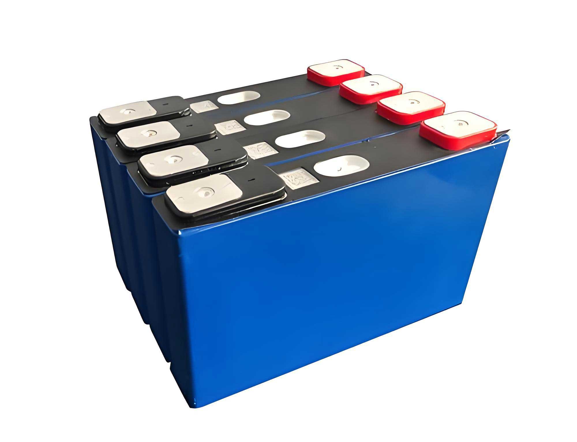
The Battery Management System (BMS) is the intelligence behind the LiFePO4 battery pack, ensuring safe and efficient operation. Its functions are multifaceted: real-time monitoring, state estimation,均衡, and protection. The BMS continuously measures cell voltages \( V_i \), temperatures \( T_i \), pack current \( I_{\text{pack}} \), and total voltage \( V_{\text{total}} \). Data acquisition occurs at frequencies up to 10 Hz, enabling rapid response to anomalies. To prevent overcharge and over-discharge, the BMS enforces voltage limits, such as \( V_{\text{cell, max}} = 3.65 \, \text{V} \) and \( V_{\text{cell, min}} = 2.5 \, \text{V} \) for LiFePO4 cells. Temperature thresholds, typically \( T_{\text{max}} = 55°C \) and \( T_{\text{min}} = -20°C \), trigger thermal management interventions.
State of Charge (SOC) estimation is performed using a Coulomb counting method combined with voltage correction. The SOC at time \( t \), denoted \( SOC(t) \), is computed as:
$$ SOC(t) = SOC(t_0) + \frac{1}{C_{\text{nominal}}} \int_{t_0}^t \eta(I(\tau)) \cdot I(\tau) \, d\tau $$
where \( C_{\text{nominal}} \) is the nominal battery capacity (e.g., 200 Ah), \( \eta(I) \) is the current-dependent efficiency factor (typically 0.95–0.98 for LiFePO4 batteries), and \( I(\tau) \) is the current (positive for discharge, negative for charge). The BMS also incorporates a Kalman filter to reduce errors from sensor noise and capacity fade. State of Health (SOH) is tracked using impedance spectroscopy, with degradation modeled as:
$$ \text{SOH} = \frac{C_{\text{actual}}}{C_{\text{nominal}}} \times 100\% $$
where \( C_{\text{actual}} \) diminishes with cycle count. For LiFePO4 batteries, the capacity fade after \( N \) cycles can be approximated by an empirical formula:
$$ C_{\text{actual}} = C_{\text{nominal}} \cdot (1 – \alpha \cdot N^\beta) $$
with \( \alpha \approx 10^{-5} \) and \( \beta \approx 1.5 \) under typical operating conditions.
Cell均衡 is achieved through active balancing circuits that redistribute energy from higher-voltage cells to lower-voltage ones, minimizing pack imbalance. The均衡 current \( I_{\text{bal}} \) is controlled to maintain voltage differences within 10 mV. Fault detection employs two-tier alerts: Level 1 warnings for minor deviations (e.g., temperature rise of 5°C above ambient) and Level 2 trip actions for severe faults (e.g., cell voltage exceeding 3.7 V), which disconnect the affected module via relays. Communication protocols, such as CAN bus, link the BMS with the charge-discharge management system and main controller, facilitating coordinated operation.
The charge-discharge strategy optimizes energy flow between the grid, LiFePO4 battery, and load. The hardware configuration includes a wellsite transformer (50 kVA/380 V), a bidirectional charger, DC/DC converters, and the battery pack. The management system implements a rule-based algorithm. Let \( P_{\text{load}}(t) \) be the load power, \( P_{\text{grid}}(t) \) the grid-supplied power (limited to 50 kVA), and \( P_{\text{bat}}(t) \) the battery power (positive for discharge, negative for charge). The power balance equation is:
$$ P_{\text{load}}(t) = P_{\text{grid}}(t) + P_{\text{bat}}(t) $$
The grid power is constrained by the transformer rating: \( P_{\text{grid}}(t) \leq 50 \, \text{kW} \). The battery power is limited by its SOC and current capabilities: \( -P_{\text{charge, max}} \leq P_{\text{bat}}(t) \leq P_{\text{discharge, max}} \), where \( P_{\text{discharge, max}} = V_{\text{bat}} \times 450 \, \text{A} \) and \( P_{\text{charge, max}} = V_{\text{bat}} \times 300 \, \text{A} \) for sustained operations. The control logic follows these rules:
- If \( P_{\text{load}}(t) \leq P_{\text{grid}}(t) \) and \( SOC < 100\% \), then \( P_{\text{bat}}(t) = -(P_{\text{grid}}(t) – P_{\text{load}}(t)) \) (charging).
- If \( P_{\text{load}}(t) \leq P_{\text{grid}}(t) \) and \( SOC = 100\% \), then \( P_{\text{bat}}(t) = 0 \) (grid only).
- If \( P_{\text{load}}(t) > P_{\text{grid}}(t) \), then \( P_{\text{bat}}(t) = P_{\text{load}}(t) – P_{\text{grid}}(t) \) (discharging).
- If \( P_{\text{bat}}(t) > P_{\text{discharge, max}} \) or \( SOC < 20\% \), suspend operation.
During regenerative braking, when the motor acts as a generator, the back-emf current \( I_{\text{regen}} \) is directed to charge the battery if \( SOC < 95\% \); otherwise, it is dissipated through a braking resistor of resistance \( R_{\text{brake}} \), with power dissipation \( P_{\text{brake}} = I_{\text{regen}}^2 \cdot R_{\text{brake}} \). This strategy maximizes energy efficiency and extends battery life.
The thermal management system maintains the LiFePO4 battery within an optimal temperature range of 15°C to 35°C. It employs a dual-mode approach: cooling via liquid chilling and heating via electric elements. The cooling system uses an embedded liquid-cooled unit with a coefficient of performance (COP) of 2.5–3.0. The heat removal rate \( \dot{Q}_{\text{cool}} \) is given by:
$$ \dot{Q}_{\text{cool}} = \dot{m} \cdot c_p \cdot \Delta T $$
where \( \dot{m} \) is the coolant mass flow rate, \( c_p \) is the specific heat capacity, and \( \Delta T \) is the temperature difference across the battery pack. The heater power \( P_{\text{heater}} \) is regulated using PID control to achieve a setpoint temperature \( T_{\text{set}} \). The thermal dynamics can be modeled as:
$$ C_{\text{th}} \frac{dT}{dt} = P_{\text{loss}} – \dot{Q}_{\text{cool}} + P_{\text{heater}} $$
where \( C_{\text{th}} \) is the thermal capacitance of the battery pack, and \( P_{\text{loss}} = I^2 R_{\text{internal}} \) is the Joule heating. The system is powered by the LiFePO4 battery’s high-voltage DC bus, ensuring operation during grid outages. Temperature sensors provide feedback for closed-loop control, with hysteresis bands to prevent frequent cycling.
Field trials were conducted to validate the performance of the LiFePO4 battery-based energy storage workover rig. The test site utilized a 50 kVA transformer, simulating typical wellsite conditions. The rig performed minor repair作业, extracting 142 tubing strings and 168 sucker rods over approximately 8 hours. The average hoisting rate was 40 strings per hour, meeting design targets. Power consumption was meticulously logged: total energy usage was 264 kWh, with grid electricity contributing 220 kWh and the LiFePO4 battery supplying 44 kWh. The battery’s SOC fluctuated between 30% and 95% during operations, demonstrating effective load-leveling. Peak currents reached 450 A during lifting phases, with voltage sag of less than 5%, confirming the robustness of the LiFePO4 battery. The thermal management system maintained pack temperatures between 20°C and 40°C despite ambient variations from 10°C to 30°C. Post-trial analysis showed no cell degradation, underscoring the longevity of the LiFePO4 battery.
To quantify the economic and environmental benefits, I performed a comparative analysis between diesel, conventional electric, and LiFePO4 battery储能 rigs. Assuming an annual operation of 2000 hours, the energy costs and emissions are summarized in Table 2. The LiFePO4 battery system reduces fuel consumption by 100% compared to diesel and cuts grid dependency by 20–30% relative to plain electric rigs.
| Metric | Diesel-Powered Rig | Grid-Electric Rig (No Storage) | LiFePO4 Battery储能 Rig |
|---|---|---|---|
| Energy Cost (USD/hour) | 25–30 (fuel-based) | 10–15 (electricity) | 8–12 (electricity + storage) |
| CO₂ Emissions (kg/hour) | 60–80 | 0 (at site) | 0 (at site) |
| Noise Level (dB) | 85–95 | 70–80 | 65–75 |
| Maintenance Interval (hours) | 500 | 1000 | 1500 |
| Peak Power Capability | High | Limited by grid | High, via battery |
| Grid Dependency | None | 100% | 50–70% |
The LiFePO4 battery’s cycle life of over 6000 cycles translates to a service life exceeding 5 years under typical oilfield usage, with a levelized cost of storage (LCOS) calculated as:
$$ \text{LCOS} = \frac{C_{\text{capital}} + \sum_{t=1}^N \frac{C_{\text{O&M}}}{(1+r)^t}}{\sum_{t=1}^N \frac{E_{\text{output}}}{(1+r)^t}} $$
where \( C_{\text{capital}} \) is the initial battery cost, \( C_{\text{O&M}} \) is annual operation and maintenance cost, \( E_{\text{output}} \) is annual energy output, \( r \) is the discount rate, and \( N \) is the lifespan. For the LiFePO4 battery system, LCOS is estimated at 0.12–0.15 USD/kWh, competitive with diesel generators.
In conclusion, the integration of LiFePO4 batteries into oilfield workover rigs represents a significant advancement in clean energy technology. By addressing the limitations of grid power, the LiFePO4 battery储能 system enables high-performance operations with reduced emissions, noise, and operational costs. The successful field trials demonstrate its reliability and efficiency, paving the way for broader adoption in drilling, production, and other oilfield equipment. The LiFePO4 battery’s inherent safety, long cycle life, and temperature resilience make it an ideal choice for harsh environments. Future work will focus on optimizing battery management algorithms, exploring hybrid systems with renewables, and scaling the technology for larger rigs. As the oil and gas industry transitions towards sustainability, the LiFePO4 battery stands as a cornerstone for innovation.