
Lithium iron phosphate (LiFePO4) batteries are a cornerstone of modern energy storage technology, prized for their inherent safety, long cycle life, and environmental friendliness compared to other lithium-ion chemistries. Their widespread adoption spans electric vehicles, portable electronics, and, critically, large-scale grid storage systems. In these stationary applications, massive battery packs or modules comprising hundreds or thousands of individual cells are commonplace. While the LiFePO4 chemistry itself is thermally stable, the sheer scale and energy density of these systems introduce significant safety challenges. One of the most critical failure modes is overcharging, where a cell is forced to accept charge beyond its designed capacity. This condition can trigger exothermic side reactions, leading to rapid temperature rise, gas generation, and, in extreme cases, thermal runaway. In a densely packed module, the heat and mechanical stress generated by an overcharged cell do not exist in isolation; they propagate to neighboring cells, potentially inducing cascading failures. Understanding this thermal propagation is therefore paramount for designing safer battery systems. This article provides a comprehensive analysis of the thermal propagation mechanisms between cells, with a specific focus on comparing the behavior of two prevalent LiFePO4 battery form factors: pouch cells and prismatic aluminum (hard-case) cells.
The fundamental heat generation within a lithium iron phosphate battery during operation can be described by the Bernardi heat generation model. The total volumetric heat generation rate, $$ \dot{Q}_{total} $$, is the sum of reversible (entropic) heat and irreversible heat:
$$ \dot{Q}_{total} = \dot{Q}_{rev} + \dot{Q}_{irr} $$
where:
- $$ \dot{Q}_{rev} = I T \frac{dU_{ocv}}{dT} $$ represents the reversible heat due to entropy changes in the electrode reactions. Here, \( I \) is the current (positive for charging), \( T \) is the absolute temperature, and \( \frac{dU_{ocv}}{dT} \) is the entropy coefficient or temperature dependence of the open-circuit voltage.
- $$ \dot{Q}_{irr} = I (V_{t} – U_{ocv}) = I^2 R_{total} $$ represents the irreversible heat, which is primarily Joule heating. \( V_{t} \) is the terminal voltage, and \( R_{total} \) is the total internal resistance, comprising ohmic resistance (\( R_{\Omega} \)) and polarization resistance (\( R_{ct} \)).
Under normal operating conditions for a LiFePO4 battery, the irreversible Joule heating dominates the heat generation profile. However, during overcharge, the scenario changes drastically. As the cell voltage is pushed beyond its safe upper limit (typically above 3.65V for LiFePO4), a cascade of deleterious electrochemical reactions is initiated:
- Electrolyte Oxidation: At the positive electrode, the electrolyte solvents (e.g., ethylene carbonate, dimethyl carbonate) become thermodynamically unstable and begin to oxidize, releasing heat and gas (e.g., CO2, CO).
- Current Collector Dissolution: The aluminum current collector at the positive electrode can corrode at high voltages.
- Lithium Plating and SEI Decomposition: At the negative electrode, lithium ions cannot be intercalated into the graphite structure once it is full. Instead, they plate as metallic lithium on the surface. This lithium is highly reactive and can react exothermically with the electrolyte. Furthermore, the Solid Electrolyte Interphase (SEI) layer, which is stable under normal conditions, begins to decompose at elevated temperatures, further accelerating reactions.
These parasitic reactions cause a sharp increase in both $$ \dot{Q}_{irr} $$ (due to increased internal resistance from gas bubbles and decomposition products) and $$ \dot{Q}_{rev} $$, leading to a dangerous positive feedback loop: heat accelerates reactions, which generate more heat. The energy balance for a single cell can be expressed as:
$$ \rho C_p \frac{\partial T}{\partial t} = \nabla \cdot (k \nabla T) + \dot{Q}_{total} $$
where \( \rho \) is density, \( C_p \) is specific heat capacity, \( k \) is thermal conductivity, and \( \nabla \cdot (k \nabla T) \) represents heat conduction within the cell. For a cell in an enclosure or module, heat exchange with the environment and adjacent cells occurs via conduction (through busbars and module structure), convection (to air or coolant), and radiation.
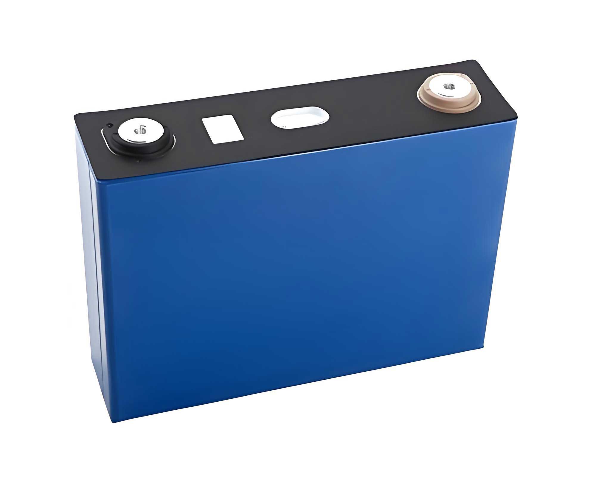
The choice of cell format significantly influences this thermal and mechanical behavior. Pouch cells use a lightweight, flexible laminated aluminum-plastic film as their outer casing. This allows for efficient heat dissipation from a large surface area but provides minimal mechanical constraint. Under internal pressure from gas generation during overcharge, a pouch cell will swell significantly. In contrast, prismatic aluminum cells are housed in a rigid metal case. This case provides excellent mechanical strength and containment but can act as a pressure vessel if venting is not timely, and its thermal conductivity can lead to different surface temperature distributions.
The experimental investigation of thermal propagation typically involves subjecting one cell in a configured pair or array to controlled overcharge while monitoring thermal and mechanical responses. A standard setup involves placing test cells in a safety chamber. One cell (the “overcharged cell”) is connected to a charger and subjected to a constant-current charge beyond its voltage cutoff. The adjacent cell (the “neighbor” or “propagation cell”) is left electrically isolated. Monitoring equipment includes:
- Thermocouples: Attached to key locations: terminals (positive/negative) and the geometric center of the large face of each cell.
- Infrared (IR) Camera: Provides a full-field, non-contact temperature map to visualize hot spots and heat flow.
- Voltage and Current Data Loggers.
- Visible Light Camera: To record physical deformations, venting events, or smoke emission.
Key test parameters include the spacing between cells (e.g., direct contact, 1 cm gap, 5 mm gap) and the overcharge rate (e.g., 0.5C, 1C). The C-rate defines the charge/discharge current relative to the battery’s capacity (e.g., a 0.5C rate for a 100 Ah battery is 50 Amps).
The thermal and mechanical response of a LiFePO4 battery to overcharge reveals stark differences between pouch and prismatic aluminum formats. The primary metrics of interest are maximum temperature rise (\( \Delta T_{max} \)), average temperature rise rate (\( \overline{\dot{T}} \)), and the physical deformation.
| Parameter | Prismatic Aluminum Cell | Pouch Cell |
|---|---|---|
| Casing Material | Rigid Aluminum | Flexible Aluminum-Plastic Laminate |
| Mechanical Constraint | High | Very Low |
| Typical Response to Overcharge | Moderate swelling, eventual venting via safety valve. | Severe swelling, often leading to pouch rupture/seam failure. |
| Primary Failure Mode (Overcharge) | Pressure build-up followed by controlled venting. | Unconstrained expansion leading to pouch breach and uncontrolled gas/electrolyte release. |
When subjected to the same overcharge current (e.g., 0.5C), the aluminum hard-case LiFePO4 battery typically exhibits a higher peak temperature and a faster temperature rise rate compared to the pouch LiFePO4 battery. Data from representative experiments are summarized below:
| Cell Type | Overcharged Cell \( \Delta T_{max} \) | Overcharged Cell \( \overline{\dot{T}} \) (°C/s) | Neighbor Cell \( \Delta T_{max} \) (Contact) | Neighbor Cell \( \overline{\dot{T}} \) (Contact) (°C/s) |
|---|---|---|---|---|
| Aluminum Hard-case | ~65 °C | ~0.039 | ~44 °C | ~0.022 |
| Pouch Cell | ~57 °C | ~0.014 | < 10 °C | ~0.002 |
The higher \( \overline{\dot{T}} \) in the aluminum cell suggests more intense internal heat generation or less effective heat dissipation from the core to the surface in the short term. However, the rigid case confines the gases, potentially leading to higher internal pressures and temperatures before the safety valve opens. The pouch cell, while reaching a slightly lower peak temperature, swells dramatically, increasing its surface area and possibly dissipating heat more effectively through the thin casing, resulting in a lower average rise rate.
The propagation of heat to a neighboring cell is governed by the mode of heat transfer, which is critically dependent on spacing. Heat transfer \( \dot{Q}_{prop} \) can be modeled as a combination of radiation, conduction through intervening material/air, and later-stage conduction if cells come into physical contact due to swelling.
- Radiation: $$ \dot{Q}_{rad} = \epsilon \sigma A (T_{hot}^4 – T_{cold}^4) $$, where \( \epsilon \) is emissivity, \( \sigma \) is the Stefan-Boltzmann constant, and \( A \) is the area. This is typically a minor contributor at these temperature ranges.
- Conduction through Air Gap: For a small gap, conduction through air (or other gas) is significant. The heat flux can be approximated by $$ q” = \frac{k_{air}}{d} (T_{hot} – T_{cold}) $$, where \( d \) is the gap distance.
- Direct Contact Conduction: Once swelling causes contact, heat transfer becomes much more efficient: $$ q” \propto k_{contact} (T_{hot} – T_{cold}) $$, where \( k_{contact} \) depends on the contact pressure and interface materials.
For an aluminum hard-case LiFePO4 battery, the propagation is strongly distance-dependent. With a gap (e.g., 1 cm), the neighboring cell experiences minimal temperature rise, often less than 5°C, as air is a poor conductor. When placed in direct contact, however, the neighbor’s temperature can soar to over 40°C because the rigid metal cases provide an excellent conductive path for heat. The mechanical force from the swelling overcharged cell is usually insufficient to significantly displace the rigid neighbor, so the contact area and pressure remain relatively stable, facilitating steady conductive heat transfer.
For a pouch LiFePO4 battery, the propagation mechanics are more complex and dominated by mechanical interaction. In a direct-contact configuration, the swelling force of the overcharged pouch cell is immense due to the lack of constraint. This force can push, deform, or even eject the neighboring cell, breaking the thermal contact. Consequently, while the neighbor might experience a brief, rapid temperature spike upon initial contact, the subsequent temperature rise can be limited as the gap reopens. Surprisingly, a small initial gap (e.g., 1 cm) might lead to more effective heating of the neighbor. The overcharged pouch cell swells to fill the gap, establishing a large, conformal contact area with the neighbor’s flexible surface. This creates a good thermal bridge, leading to a higher and more sustained temperature rise in the neighbor compared to the direct-contact case where the neighbor is pushed away. This underscores a critical point: for pouch LiFePO4 batteries, mechanical stress propagation often precedes and dictates thermal propagation. The neighbor cell experiences not just thermal stress from heating but also significant mechanical stress from compression or bending, which can damage internal components like electrodes and separators, creating latent failure points.
| Cell Format | Dominant Propagation Mechanism (Contact) | Risk to Neighbor Cell |
|---|---|---|
| Aluminum Hard-case | Stable Conductive Heat Transfer | Primarily Thermal Stress (High Temperature) |
| Pouch Cell | Unstable Mechanical Contact Leading to Intermittent Heat Transfer | Combined Thermal and Significant Mechanical Stress |
The implications of these findings for battery pack and module design are profound. Designers must adopt distinct strategies for systems based on aluminum hard-case versus pouch LiFePO4 batteries.
For Modules with Aluminum Hard-case LiFePO4 Batteries:
The primary challenge is managing conductive heat transfer. Cell spacing is the most critical parameter. Incorporating intentional, thermally resistive gaps or using materials with low thermal conductivity in the module structure between cells is essential to decouple them thermally. Active cooling systems (liquid or forced air) must be designed to effectively remove heat not just during normal operation but also during a single-cell failure event, preventing the neighboring cells from reaching critical temperatures. Robust cell holders must withstand the mechanical force from a swelling cell without transferring excessive stress to neighbors.
For Modules with Pouch LiFePO4 Batteries:
The primary challenge is managing mechanical expansion and its consequences. Module design must accommodate significant cell swelling without allowing cells to exert crushing forces on their neighbors. This may involve designing rigid external module constraints with internal “breathing room” or using compliant materials between cells that can compress. The thermal management system must account for the changing geometry and contact conditions. Furthermore, the Battery Management System (BMS) must be extremely sensitive to cell voltage discrepancies to prevent overcharge, as the mechanical domino effect from a single swelling pouch cell can be severe.
In both cases, advanced thermal runaway propagation barriers are being developed. These include intumescent materials that expand when heated to create an insulating char, phase change materials (PCMs) that absorb latent heat, and dedicated fire-retardant plates between cells.
Understanding thermal propagation in LiFePO4 batteries is not merely an academic exercise but a fundamental requirement for engineering safe, reliable energy storage systems. While the lithium iron phosphate chemistry offers a stable foundation, the system-level safety is dictated by the thermal and mechanical interactions between cells during abuse. This analysis highlights a clear dichotomy: systems built with aluminum hard-case LiFePO4 batteries are primarily threatened by stable, efficient conductive heat transfer during an overcharge event, making thermal isolation a key design goal. In contrast, systems utilizing pouch LiFePO4 batteries face a dual threat where massive mechanical deformation drives intermittent thermal contact and inflicts direct physical damage on adjacent cells, making mechanical accommodation and expansion management paramount. Future research directions include quantifying the mechanical stresses involved, developing advanced materials to mitigate both heat and force transfer, and creating multi-physics models that couple electrochemical, thermal, and mechanical behaviors to predict propagation dynamics accurately. As the demand for energy storage grows, so does the imperative to master these failure dynamics, ensuring that the safety promise of the LiFePO4 battery is fully realized at the system level.