
The global emphasis on environmental sustainability and the transition to clean energy has profoundly impacted all industrial sectors, including railway infrastructure and maintenance. Urban rail operators and maintenance fleets are increasingly seeking to integrate hybrid and even pure-electric powertrains into their rolling stock and specialized engineering vehicles. This shift demands energy storage solutions that are not only powerful and efficient but also safe, durable, and cost-effective over their entire lifecycle. Among the various battery chemistries available, lithium iron phosphate (LiFePO4) has emerged as a leading contender for heavy-duty applications. This article provides a comprehensive, first-person account of the development, testing, and practical application of a modular, high-voltage LiFePO4 battery system specifically engineered for use in rail-bound equipment, such as Battery Electric Engineering Vehicles.
1. Architectural and Structural Design Philosophy
The core design principle behind this LiFePO4 battery system is modularity and scalability. The system is composed of several identical, self-contained battery subsystems, termed “branches.” Each branch is housed within a standardized battery cabinet, forming a complete functional unit. This approach offers significant advantages in manufacturing, maintenance, and system configuration flexibility.
A single branch cabinet integrates the following key components:
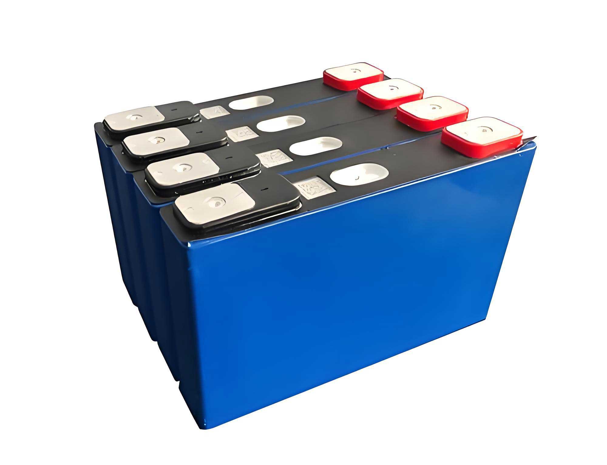
- Battery Packs: Six individual battery packs, each containing numerous LiFePO4 power cells arranged in series and parallel to achieve the desired voltage and capacity.
- Liquid Cooling System: A dedicated thermal management loop, including a coolant distribution manifold, pumps, and a chiller/heater unit. The coolant reservoir can be mounted internally or externally based on vehicle layout constraints.
- High-Voltage Distribution Unit (HVDU): Manages the connection and disconnection of the high-voltage circuit, incorporating contactors, pre-charge circuits, and fuses for safety.
- Battery Management System (BMS): The electronic “brain” of the subsystem, responsible for monitoring and protecting the LiFePO4 battery packs.
- Fire Suppression System: An integrated fixed fire extinguishing unit designed to detect and suppress thermal events within the cabinet.
- Ancillary Systems: Includes necessary enclosures, mounting frames, wiring harnesses, and maintenance access spaces.
The specifications for a single branch are meticulously chosen for railway traction:
| Parameter | Specification | Note |
|---|---|---|
| Rated Capacity | 230 Ah | Per branch |
| Rated Voltage | 800 V DC | Nominal operating voltage |
| Rated Energy | 185 kWh | Calculated as Capacity × Voltage |
| Maximum Continuous Current | 1C (230A) | At room temperature |
| Cycle Life | ≥ 3500 cycles | At 1C, 25°C, 100% Depth of Discharge (DOD) |
| Operational Life | ≥ 5 years | In service conditions |
| Cell Chemistry | Lithium Iron Phosphate (LiFePO4) | Prismatic power cells |
| Ingress Protection (IP) | IP64 (Battery Packs), IP32 (Overall Cabinet) | Dust and water resistance |
| Communication Interface | CAN & Ethernet | For BMS and system control |
The selection of high-quality LiFePO4 cells is paramount. This chemistry provides an excellent balance of safety (inherently stable cathode material), long cycle life, and good power capability. The internal structure of the packs is designed for optimal thermal conduction and mechanical stability. The entire LiFePO4 battery system is charged via an on-board generator (in hybrid applications) or a ground-based charging station, and it seamlessly provides power for vehicle traction and accepts energy during regenerative braking.
2. System Functionality and Critical Features
2.1 Modular LiFePO4 Battery System Architecture
The parallel operation of multiple branches is fundamental to achieving the high energy and power demands of a rail vehicle. This architecture provides redundancy; if a fault is detected in one branch’s LiFePO4 battery pack or management system, it can be isolated and disconnected, allowing the vehicle to continue operation or at least be moved to a safe location using the remaining healthy branches. This “graceful degradation” is crucial for railway operational safety. By segmenting the total energy into several independent LiFePO4 battery subsystems, the potential severity of a single thermal runaway event is contained, preventing catastrophic failure propagation.
Each cabinet is equipped with a visual and audible alarm system. Status indicators provide operators with at-a-glance information, while fault conditions trigger distinct alarms to prompt immediate attention.
2.2 Hierarchical Battery Management System (BMS)
The BMS employs a master-slave architecture. Slave boards are responsible for precise measurement at the most granular level:
- Voltage Monitoring: Every individual LiFePO4 cell voltage and the voltage of each series connection within a pack is monitored.
- Temperature Monitoring: Multiple temperature sensors (NTC thermistors) are strategically placed within each LiFePO4 battery pack to monitor cell and interconnect temperatures.
- Current Monitoring: A high-precision Hall-effect sensor measures the total current flowing into and out of each branch.
The master BMS unit aggregates this data, performs critical calculations such as State of Charge (SOC), State of Health (SOH), and State of Power (SOP), and enforces safety limits. It manages cell balancing, communicates with the vehicle’s central controller, and logs operational data. The key functions can be summarized by the following control logic for discharge current limitation based on temperature (T) and SOC:
$$ I_{disch\_max}(T, SOC) = \begin{cases} 0, & \text{if } T \leq T_{min} \text{ or } T \geq T_{max} \text{ or } SOC \leq SOC_{min}\\ C_{rate}(T) \times C_{nom}, & \text{if } SOC_{min} < SOC < SOC_{max} \\ derate(SOC), & \text{if } SOC \text{ approaches } SOC_{max} \end{cases} $$
Where \(C_{rate}(T)\) is the temperature-dependent maximum C-rate, \(C_{nom}\) is the nominal capacity of the LiFePO4 battery, and the derate function reduces current at very high SOC to protect the cells.
2.3 Integrated Fire Suppression System
Safety is non-negotiable. The fire suppression system uses advanced aerosol or clean agent technology. Detectors (smoke, heat, gas) within the LiFePO4 battery cabinet provide early warning. Upon confirmation of a thermal runaway initiation—defined as an uncontrolled temperature rise in a cell leading to exothermic chain reactions—the system activates within seconds, deploying the suppressing agent directly into the affected zone. This action is designed to extinguish flames in the early stage and significantly slow down the thermal propagation, providing critical time for further safety procedures.
2.4 Advanced Thermal Management System (TMS)
The performance, lifespan, and safety of a LiFePO4 battery are intimately tied to its operating temperature. The TMS is a liquid-based, active system capable of both cooling and heating. It ensures the LiFePO4 battery operates within an optimal window (typically 15°C to 35°C) regardless of ambient conditions. During high-power charging or discharging, it removes heat. In cold climates, it pre-heats the LiFePO4 battery to enable efficient charging and discharge. The system uses a glycol-water mixture capable of operating at temperatures as low as -45°C. The cooling unit can be configured for top or side exhaust to match vehicle design.
3. Rigorous Testing and Validation Protocol
The developed LiFePO4 battery system underwent a stringent testing regimen to validate its performance and safety claims against railway standards.
3.1 Room Temperature Discharge Capacity Test
This test verifies the fundamental energy content of the LiFePO4 battery system. Following the methodology outlined in relevant technical specifications (e.g., TJ/JW127-2020), the fully charged system is discharged at a constant current of 1C (230A) until the voltage of any cell reaches the minimum cut-off limit or the system’s lower SOC limit is reached. The actual discharged capacity \(Q_{disch}\) and energy \(E_{disch}\) are calculated and must meet or exceed the rated values (230 Ah, 185 kWh). Temperature rise across all monitoring points is recorded to ensure thermal stability.
$$ Q_{disch} = \int_{t_{start}}^{t_{end}} I(t) \, dt $$
$$ E_{disch} = \int_{t_{start}}^{t_{end}} V_{sys}(t) \cdot I(t) \, dt $$
3.2 Standard Charging Protocol Compliance
Interoperability with standard charging infrastructure is essential. The system was tested with a ground-based DC charging station compliant with GB/T 27930-2023. The test validates the digital communication protocol between the vehicle’s BMS (for the LiFePO4 battery) and the charger, ensuring proper handshake, parameter negotiation, charging profile control, and safe termination under normal and fault conditions.
3.3 Noise Emission Testing
As the cooling system’s compressor and fans are primary noise sources, their acoustic impact was quantified. Following guidelines (e.g., TJ/JW128), sound pressure level measurements were taken at multiple points 1 meter from the operational cabinet surface. The average of these readings must comply with low-noise requirements for railway vehicle interiors. A sample of recorded data is presented below:
| Point 1 | Point 2 | Point 3 | Point 4 | Point 5 | Point 6 | Point 7 |
|---|---|---|---|---|---|---|
| 87.00 | 86.08 | 86.42 | 78.82 | 78.97 | 79.78 | 78.13 |
| Point 8 | Point 9 | Point 10 | Point 11 | Point 12 | Point 13 | Point 14 |
| 75.32 | 76.40 | 74.48 | 71.67 | 79.17 | 78.05 | 78.71 |
| Point 15 | Point 16 | Point 17 | Point 18 | Point 19 | Point 20 | Average |
| 83.06 | 82.47 | 81.97 | 80.77 | 79.53 | 79.83 | ~79.8 dBA |
3.4 Additional Validation Tests
Beyond the tests mentioned, a full validation suite for a railway-grade LiFePO4 battery system includes:
- Mechanical Vibration and Shock Tests: Simulating the harsh railway environment.
- Environmental Tests: High/low temperature operation and storage, humidity resistance.
- Electrical Safety Tests: Dielectric strength, insulation resistance, short-circuit protection.
- Abuse Tests: Overcharge, over-discharge, and crush tests (often on sample modules).
4. Application in Electric Battery Engineering Vehicles: A Case Study
4.1 Vehicle Integration and Layout
In a typical Battery Electric Engineering Vehicle, two branches of the LiFePO4 battery system are installed in parallel to provide the necessary power and energy. They are symmetrically placed near the center of the vehicle frame, aligning with the center of gravity to ensure stable dynamic behavior. The layout often features a central corridor between the cabinets for easy access, inspection, and maintenance. High-voltage traction cables are routed underneath the floor, safely integrated within the vehicle frame structure.
4.2 Comparative Advantage of LiFePO4 Chemistry
The transition from traditional lead-acid batteries to LiFePO4 technology represents a paradigm shift. The following table contrasts the two technologies for traction applications:
| Parameter | Lead-Acid Battery | LiFePO4 Battery | Impact & Advantage of LiFePO4 |
|---|---|---|---|
| Cycle Life (100% DOD) | < 500 cycles | ≥ 3500 cycles | ~7x longer life, drastically lower lifecycle cost. |
| Energy Density (Wh/kg) | ~30-50 | ~100-130 | ~2-3x lighter for same energy, or more compact. |
| Charge Time (10-90%) | ~6 hours | ~1-2 hours | Faster turnaround, higher vehicle availability. |
| Memory Effect | Yes (slight) | No | No need for periodic full discharges, simpler usage. |
| Temperature Sensitivity | High (Poor low-temp performance) | Moderate (Wide operating range with TMS) | More reliable operation in varied climates. |
| Maintenance | Regular watering, equalization | Minimal (Only periodic capacity check) | Lower operational overhead. |
| Efficiency (Round-trip) | ~75-80% | ~92-97% | Less energy wasted as heat, longer range. |
While other lithium chemistries like Lithium Titanate (LTO) offer even longer cycle life (>10,000 cycles), their cost per kWh is prohibitively high (often 3x that of LiFePO4). A pragmatic strategy is to use a LiFePO4 battery system and plan for one mid-life replacement. This still provides a total service life exceeding that of many vehicle components at a fraction of the cost of an LTO-based system.
Even at its end-of-life, defined as capacity fade to 80% of nominal, a LiFePO4 battery system retains substantial capability. For instance, a system with an initial 370 kWh gross capacity could still power a vehicle for several hours under typical loads, ensuring operational viability until scheduled replacement.
4.3 Technical Challenges and Solutions
Challenge 1: Cooling System Weatherproofing. Rail vehicles must withstand heavy rain. The side-vented cooling system posed a potential water ingress risk. The solution was a multi-stage design: the exhaust duct inside the cabinet is angled downwards, and includes a condensation drain channel connected to a hose leading under the vehicle. Furthermore, the exterior vehicle body grille opposing this vent features its own perimeter drainage channel. This creates a dual barrier against water penetration.
Challenge 2: Cooling Unit Power Supply. The cooling unit’s compressor requires a 380VAC supply, but the LiFePO4 battery system outputs high-voltage DC (up to 920V). Direct power conversion within the battery cabinet is limited by the voltage ratings of commercially available compressor drives (~750-820V max). Therefore, the solution involves the vehicle’s main auxiliary inverter converting the high-voltage DC to 380VAC, which is then distributed back to power the cooling units. While this adds some system complexity, it is a robust and reliable approach. Future advancements in high-voltage compressor technology may simplify this architecture.
4.4 Charging Infrastructure Strategy
Two primary charging methods are supported:
- On-board Charger: For flexibility, but requires high power (e.g., 360kW for a 1-hour charge) and adds weight/cost to the vehicle.
- Ground-based Charger: The preferred method for depot charging. A 300kW dual-gun DC charging station can charge the two-branch LiFePO4 battery system in approximately 1 hour (10-90% SOC). The vehicle is equipped with two standard charging sockets to connect to both guns simultaneously.
The charging power \(P_{charge}\) required for a desired charge time \(\Delta t\) and usable energy capacity \(E_{usable}\) is given by:
$$ P_{charge} \approx \frac{E_{usable}}{\Delta t \cdot \eta_{charge}} $$
where \(\eta_{charge}\) is the charging efficiency (~0.95). For \(E_{usable} = 0.8 \times 370 \text{ kWh} = 296 \text{ kWh}\) and \(\Delta t = 1 \text{ hour}\), \(P_{charge} \approx 312 \text{ kW}\).
4.5 Traction and Endurance Simulation for a Specific Route
A detailed simulation was conducted for a 33km engineering route with gradients up to 30‰. The vehicle model had a mass of 56 tons with a 110-ton trailing load. The key constraints are the maximum continuous power from the LiFePO4 battery system (e.g., 300kW per motor group) and the maximum traction force (100kN).
Traction Force Analysis: The total resistance \(F_{total}\) on a gradient is the sum of rolling resistance \(F_{roll}\) and gradient resistance \(F_{grade}\).
$$ F_{roll} = (m_{vehicle} + m_{load}) \cdot g \cdot w’_0 $$
$$ F_{grade} = (m_{vehicle} + m_{load}) \cdot g \cdot i $$
$$ F_{total} = F_{roll} + F_{grade} $$
Where \(g\) is gravity, \(i\) is the gradient (30‰ = 0.03), and \(w’_0\) is the specific rolling resistance (calculated using a quadratic function of speed \(v\): \(A + Bv + Cv^2\)). The analysis confirmed that the available 100kN traction force is sufficient to overcome the maximum calculated resistance of ~48.7kN on the steepest grade.
Endurance (Range) Calculation: The decisive factor is the usable energy from the LiFePO4 battery. Accounting for system efficiencies and a 20% capacity reserve, the effective energy is:
$$ E_{effective} = Q_{nom} \cdot V_{nom} \cdot \eta_{bat\_disch} \cdot \eta_{drivetrain} \cdot DOD_{usable} $$
Applying this to both chemistries:
- LiFePO4: \(460 \text{ Ah} \times 800 \text{ V} \times 0.97 \times 0.90 \times 0.8 / 1000 \approx 257 \text{ kWh}\)
- Lead-Acid: \(400 \text{ Ah} \times 800 \text{ V} \times 0.90 \times 0.90 \times 0.8 / 1000 \approx 207 \text{ kWh}\)
The vehicle’s steady-state power demand \(P_{demand}\) at speed \(v\) is \(P_{demand} = F_{roll} \cdot v / 3.6\). The endurance \(T\) and range \(S\) are then:
$$ T = \frac{E_{effective}}{P_{demand}} $$
$$ S = v \cdot T $$
Simulation results for a constant 20 km/h speed over the mixed route clearly demonstrate the superior endurance provided by the LiFePO4 battery system.
| Battery Type | Effective Energy (kWh) | Avg. Power Demand* (kW) | Theoretical Endurance (h) | Theoretical Range (km) | Notes |
|---|---|---|---|---|---|
| Lead-Acid | 207 | ~45 | ~4.6 | ~92 | Limited by energy content and lower efficiency. |
| LiFePO4 | 257 | ~45 | ~5.7 | ~114 | ~24% longer range due to higher efficiency and capacity. |
* Average power demand is route-specific and includes auxiliary loads.
5. Conclusion and Future Outlook
The development and successful application of this modular LiFePO4 battery system underscore its exceptional suitability for heavy-duty rail vehicles. The system’s advantages—long cycle life, inherent safety, high energy efficiency, wide operational temperature range with active thermal management, and low total cost of ownership—make it a superior choice over traditional lead-acid batteries and a more practical solution than ultra-high-cycle-life but expensive alternatives like LTO.
The technical challenges encountered, particularly in system integration and power distribution for auxiliaries, were addressed with robust engineering solutions, resulting in a reliable and maintainable product. The modular architecture of the LiFePO4 battery system ensures scalability and operational resilience, key requirements for the railway industry.
Looking ahead, the application of LiFePO4 battery technology is poised to expand beyond battery-electric utility vehicles. Future large track maintenance machines—such as tampers, grinders, and inspection cars—can leverage this technology to enable hybrid or even fully electric operation. This will be particularly transformative for operations in environmentally sensitive areas, long tunnels where emissions are a critical concern, and high-altitude regions where diesel engine efficiency drops significantly. The journey of integrating advanced LiFePO4 battery systems into the backbone of railway maintenance and operations is just beginning, promising a greener, more efficient, and technologically advanced future for the industry.