
The proliferation of electric vehicles (EVs) represents a fundamental shift in the global automotive industry, driven by imperatives of climate change mitigation and sustainable development. At the heart of this transition lies the lithium-ion battery pack, a complex system whose performance, cost, and, most critically, safety are paramount. Innovations in battery pack design, such as Cell-to-Pack (CTP) and structural battery concepts, relentlessly pursue higher system-level energy density by simplifying or eliminating modular components. While this integration improves efficiency, it raises crucial questions about the mechanical environment of individual cells within the pack. A key, yet often underexplored, parameter in this context is the mechanical constraint or binding force applied to cells by the pack structure. This force counteracts the internal swelling pressures generated during a battery’s life, especially towards its end-of-life (EOL). This article presents a comprehensive, first-person investigation into how such binding forces fundamentally influence the safety outcomes of large-format, prismatic LiFePO4 lithium-ion batteries under various abuse conditions. Understanding this relationship is not merely academic; it provides essential data-driven insights for engineers designing safer, more robust battery systems, ensuring that the pursuit of energy density does not come at the expense of safety.
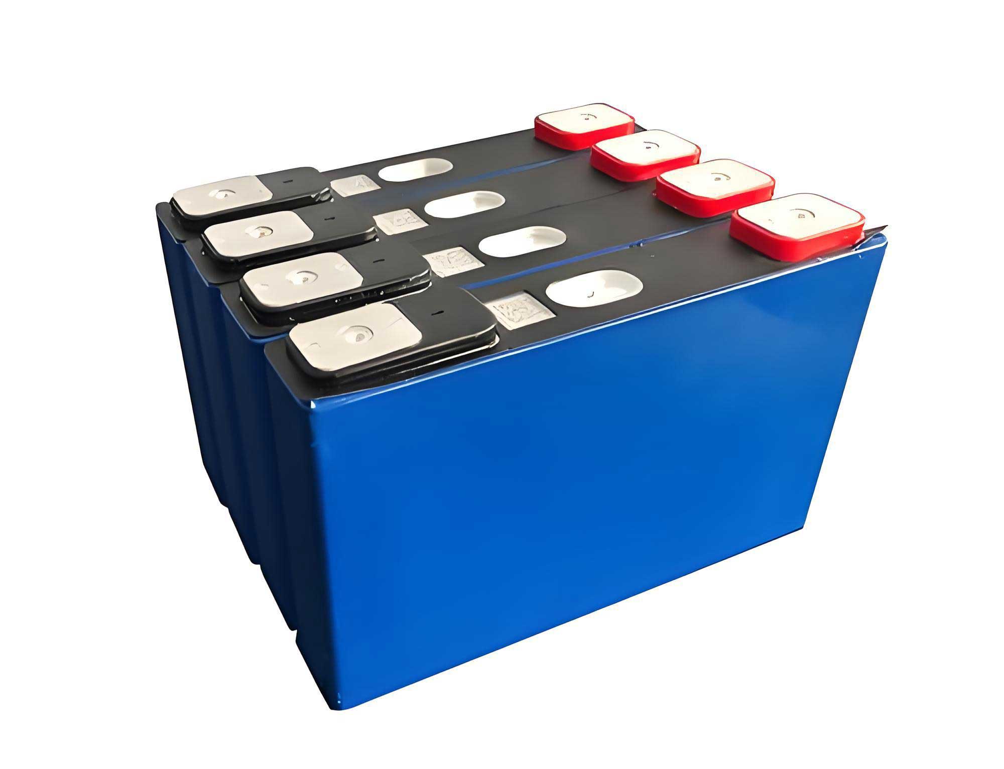
The experimental work focused on commercial-grade, prismatic aluminum-can LiFePO4 lithium-ion batteries with a nominal capacity of 172 Ah. Critically, all cells were selected at their end-of-life, defined as approximately 80% of their initial capacity after extensive 1C cycle testing. Using EOL cells is vital as they exhibit more pronounced swelling and mechanical stress, representing a worst-case scenario for pack structural integrity. A specialized test fixture with metal plates was employed to simulate the binding force present in a real battery module or pack. A force of approximately 3 kN was applied to the large faces of the cell for the “constrained” test condition. This was compared against an “unconstrained” condition where the cell was free to expand. A comprehensive safety test matrix was then executed, including Over-discharge, Overcharge, External Short Circuit, Thermal Ramp (Heating), and Nail Penetration. Multiple cells were tested for each condition to ensure statistical relevance. Parameters monitored included voltage, current, surface temperature, internal resistance, dimensional change (thickness), and mass change. Post-test analysis included visual inspection for venting, leakage, fire, and explosion.
1. Over-discharge Behavior Under Constraint
Over-discharging a LiFePO4 lithium-ion battery pushes the cell voltage below its safe operational minimum, triggering a cascade of deleterious electrochemical reactions. At the anode, the copper current collector begins to oxidize and dissolve as the potential rises: Cu → Cu+ + e–. This compromises the electrode’s structural integrity. Simultaneously, the solid-electrolyte interphase (SEI) layer on the graphite decomposes, exposing fresh graphite to the electrolyte and leading to further parasitic reactions and gas generation (e.g., C2H4, CO2). At the cathode, dissolved copper ions can plate out, potentially creating metallic dendrites that risk internal short circuits. The collective outcome is significant gas generation, swelling, increased internal resistance, and heat generation.
The effect of mechanical constraint was stark. Unconstrained LiFePO4 battery cells swelled excessively, with thickness increases averaging 41.3%. This immense swelling often exceeded the structural limits of the aluminum can’s weakest point—the bottom corner where three faces meet. Consequently, these corners ruptured, leading to electrolyte leakage. In contrast, constrained LiFePO4 battery cells exhibited significantly lower swelling (average 27% thickness increase). The binding force effectively contained the internal gas pressure, preventing catastrophic casing failure and leakage. No rupture was observed in any constrained test. The internal resistance rise was also markedly lower in constrained cells (304% average increase) compared to unconstrained ones (350% average increase), suggesting better maintained internal electrode contact. The temperature during over-discharge for an unconstrained cell peaked notably higher (94°C vs. 66°C), and its voltage profile showed unstable fluctuations, indicative of intermittent internal contact loss.
The governing relationship between generated gas, internal pressure (P), and casing strain (ΔV/V) can be modeled. Without constraint, the casing expands freely until its yield strength (σy) is exceeded at stress concentrations like corners. With constraint, the external force (Fext) adds to the casing’s resistance. The condition for leakage/rupture can be simplified as:
$$P_{internal} \cdot A_{eff} > F_{casing} + F_{ext}$$
where Aeff is the effective area, Fcasing is the force the casing can withstand based on its geometry and material yield strength, and Fext is the external binding force. For a typical prismatic LiFePO4 battery, the bottom corner has a low Fcasing. The 3 kN Fext significantly raises the right side of the inequality, preventing failure.
| Test Condition | Avg. ΔVoltage (V) | Avg. ΔInternal Resistance (%) | Avg. ΔThickness (%) | Critical Observation |
|---|---|---|---|---|
| Constrained (3 kN) | -3.374 | +304 | +27 | Swelling contained; No leakage. |
| Unconstrained | -3.375 | +350 | +41.3 | Excessive swelling; Bottom corner rupture and leakage. |
2. Overcharge Safety and the Role of Constraint
Overcharging a LiFePO4 lithium-ion battery forces excess lithium extraction from the cathode, raising its potential to levels where electrolyte oxidation becomes vigorous. Concurrently, the anode potential plummets, causing massive lithium plating and dendrite formation. These processes generate heat and gases (H2, CO, CO2, hydrocarbons) at an accelerating rate, leading to thermal runaway, often culminating in venting, fire, or explosion. The safety device in a prismatic cell is typically a vent (or burst disc) designed to open at a predetermined internal pressure, releasing gases and potentially averting catastrophic rupture.
Mechanical constraint dramatically altered the failure mode. All unconstrained cells experienced violent explosions. The casing failed at the structurally weak bottom, ejecting the jellyroll. The vent did not activate because the pressure rise was likely localized or the casing failed before the global pressure reached the vent’s threshold. The mass loss was extreme (over 1 kg), indicating near-complete combustion of cell contents. Constrained cells showed a much safer outcome. Two out of three cells underwent controlled venting; the vent operated as intended, releasing gases and preventing explosion. Only one constrained cell proceeded to thermal runaway. The binding force effectively contained the internal pressure, ensuring it built up uniformly and activated the primary safety device (the vent) rather than finding a weak structural path. The peak temperature during testing was drastically lower for constrained cells that vented (77°C) versus unconstrained explosions (305°C).
This highlights a critical system-design insight: for a vent to function as intended, the cell casing must remain intact long enough for the internal pressure to reach the vent’s actuation pressure (Pvent). Constraint ensures this by bolstering the casing’s mechanical integrity. The time to vent (tvent) can be related to the pressure buildup rate (dP/dt) from gas generation:
$$t_{vent} \approx \frac{P_{vent}}{(dP/dt)}$$
Constraint increases the effective failure pressure of the casing (Pfail), ensuring Pfail > Pvent. For an unconstrained LiFePO4 battery, Pfail (bottom corner) can be less than Pvent, leading to premature structural failure.
| Test Condition | Failure Mode | Vent Operation | Avg. Mass Loss (g) | Typical Peak Temp. |
|---|---|---|---|---|
| Constrained (3 kN) | Controlled Venting (2/3), TR (1/3) | Yes (Vent opened) | -220.6* | 77°C (vented) |
| Unconstrained | Catastrophic Explosion | No (Casing failed first) | -1358.3 | 305°C |
*Average excludes the one thermal runaway (TR) cell for mode clarity; it had significant mass loss.
3. External Short Circuit Response
An external short circuit subjects the LiFePO4 lithium-ion battery to an extremely high discharge current, leading to rapid Joule heating. The temperature rise can cause separator shrinkage/melting, triggering internal shorts, and accelerate side reactions, leading to gas generation and swelling.
Under unconstrained conditions, the external short led to more severe outcomes. The internal resistance post-test increased by an average of 34%, compared to only 5.5% for constrained cells. This suggests greater degradation or delamination within the unconstrained cell’s electrodes. Swelling was also more pronounced (36% vs. 23.5% thickness increase). One unconstrained cell even showed electrolyte leakage. The voltage and temperature profiles were telling: an unconstrained cell’s voltage dropped to zero rapidly (~120s) despite only a fraction of its capacity being discharged, indicating the onset of an internal short circuit. Its terminal temperature spiked to 342°C. The constrained cell discharged more steadily over 1000+ seconds, its voltage gradually descending, and its temperature remained significantly lower (121°C). The binding force appears to maintain better interfacial contact between cell components, promoting more uniform current distribution and heat dissipation, and physically restricting the deformation that can lead to internal shorts.
The heat generation (Q) during a short circuit is given by Joule’s law: Q = I2Rit, where I is the current, Ri is the internal resistance, and t is time. Constraint may help maintain a lower and more stable Ri by preventing contact loss. More importantly, the risk of an internal short from separator compromise is a function of temperature and mechanical strain on the separator. Constraint mitigates the mechanical strain component (ε) induced by swelling. The short circuit hazard function (H) could be conceptually modeled as:
$$H_{short} \propto \int (I(t)^2 \cdot R_i(T, \epsilon)) dt + f(T, \epsilon)_{separator}$$
Where f(T, ε)separator represents the probability of separator failure. Constraint reduces ε, thereby lowering both the resistive heat term (by stabilizing Ri) and the separator failure risk.
| Test Condition | Avg. Post-Test ΔR (%) | Avg. ΔThickness (%) | Leakage Observed? | Voltage Drop to 0V Time | Typical Peak Temp. |
|---|---|---|---|---|---|
| Constrained (3 kN) | +5.5 | +23.5 | No | >1000 s (gradual) | ~121°C |
| Unconstrained | +34 | +36 | Yes (1 of 3 cells) | ~120 s (abrupt) | ~342°C |
4. Thermal Ramp (Heating) Test and Trigger Temperatures
The thermal ramp test induces thermal runaway by externally heating the cell until internal exothermic reactions become self-sustaining. Key triggers include SEI decomposition (~90-120°C), separator melting (~135-165°C for PE/PP), and reactions between anode and binder/cathode and electrolyte at higher temperatures.
Mechanical constraint significantly delayed the onset of thermal runaway. Unconstrained cells went into runaway at approximately 158°C, while constrained cells withstood heating until about 188°C—a 30°C difference. This delay is critical for safety systems’ response time. Furthermore, the failure mode differed. Constrained cells experienced violent venting where the burst disc was completely ejected. Unconstrained cells also vented, but the vent membrane often remained attached, only deforming. This is because the unconstrained cell could swell, increasing its internal volume and thus reducing the pressure buildup rate, leading to a less violent, incomplete venting action. However, this “benefit” is deceptive, as the earlier and potentially more violent thermal runaway poses a far greater hazard.
The constraint alters the heat transfer and mechanical state within the LiFePO4 battery. By restricting swelling, it improves thermal contact between the jellyroll and the casing, potentially allowing for better heat dissipation from the core to the environment in the pre-runaway phase. More importantly, it prevents the physical distortion of the electrodes and separator that can cause internal short circuits—a potent trigger for thermal runaway. The onset temperature (Tonset) can be seen as the point where heat generation rate (Ṡ) surpasses heat dissipation rate (Ḋ): Ṡ(T, ε) > Ḋ(T). Constraint reduces ε, likely shifting the Ṡ(T) curve to higher temperatures by delaying internal shorting. The energy balance before runaway is:
$$mC_p\frac{dT}{dt} = \dot{S}_{rxn}(T, \epsilon) + \dot{S}_{Joule} – \dot{D}(T)$$
Where mCp is thermal mass, Ṡrxn is heat from chemical reactions, and ṠJoule is from internal shorts. Constraint, by minimizing ε, reduces both Ṡrxn (by maintaining stable interfaces) and eliminates ṠJoule from shorts until higher temperatures.
| Test Condition | Avg. Thermal Runaway Onset Temp. | Vent Behavior | Avg. ΔThickness Post-Test | Observation |
|---|---|---|---|---|
| Constrained (3 kN) | ~188°C | Complete disc ejection | +0.5% | Delayed TR, violent but directed venting. |
| Unconstrained | ~158°C | Incomplete opening, membrane often intact | +49.5% | Earlier TR, less violent but incomplete venting. |
5. Nail Penetration: Containing the Damage
Nail penetration is a severe test simulating an internal short circuit by physically breaching the separator. It causes localized Joule heating, melting, and can ignite electrolyte and other flammable materials, often leading to fire and jet flames.
The difference between constrained and unconstrained LiFePO4 battery cells was profound and visually dramatic. Unconstrained cells were prone to fire. Upon nail penetration, flames and intense smoke erupted from the penetration site. The casing often split along the nail path. The voltage collapsed within minutes, and temperatures soared to nearly 270°C. The massive mass loss (over 500g) confirmed combustion of cell components. Constrained cells, however, exhibited remarkably benign behavior. No fire, smoke, or significant leakage occurred. The voltage drop was minimal (~100 mV over one hour), and the temperature rise was modest (peak ~85°C). The nail appeared to create only a localized, self-limiting short circuit.
Mechanical constraint plays multiple roles here. First, it restricts the “breathing” or bulging of the cell around the nail. This likely limits the influx of fresh electrolyte and oxygen into the hot penetration zone, starving any potential fire. Second, it maintains compression on the electrodes around the nail, which may help extinguish the initial arc or hot spot by ensuring good thermal contact with the surrounding, cooler material. Third, it prevents the global deformation that could propagate the local short into a wider area. The energy released during penetration (Epen) is partially dissipated as heat (Qlocal) and partially used for mechanical work deforming the cell (Wdeform): Epen = Qlocal + Wdeform. In an unconstrained cell, Wdeform is large, but more critically, the deformation enables sustained combustion. In a constrained cell, Wdeform is minimized, and the geometry limits combustion, allowing Qlocal to dissipate without triggering cell-wide thermal runaway.
| Test Condition | Fire/Smoke | Voltage Behavior (1 hour) | Typical Peak Temp. | Avg. Mass Loss (g) | Overall Safety Outcome |
|---|---|---|---|---|---|
| Constrained (3 kN) | None | Stable, ~3.3V | ~85°C | -23.5 | Safe; No thermal event. |
| Unconstrained | Fire & Thick Smoke | Drops to 0V in ~17 min | ~269°C | -287.6* | Hazardous; Thermal runaway with fire. |
*Average heavily influenced by one fire event.
6. Synthesis and Implications for LiFePO4 Battery System Design
The collective data from these five abuse tests paints a consistent and compelling picture: the application of a moderate mechanical constraint (≈3 kN) significantly enhances the safety margin of large-format prismatic LiFePO4 lithium-ion batteries. The underlying mechanisms are interrelated:
1. Mechanical Stability: Constraint prevents excessive swelling and deformation. This maintains the integrity of the internal electrode stack, preserving electrical contact and preventing local hotspots or internal shorts induced by distortion. It also ensures the cell casing remains intact, allowing primary safety devices like vents to function as designed.
2. Thermal Management: By limiting air gaps caused by swelling, constraint improves thermal conduction from the core to the casing. This can delay the onset of thermal runaway during heating. During nail penetration, it limits oxygen and electrolyte flow, suppressing fire.
3. Pressure Management: Constraint contains internal gas pressure, turning a potentially catastrophic rupture into a controlled venting event. It ensures pressure builds uniformly to activate the vent, rather than finding a weak structural point.
The implications for designing battery packs, especially using high-integration concepts like CTP, are profound. The pack structure must be designed not just for initial assembly, but to maintain a calculable minimum preload or constraint force throughout the vehicle’s life, counteracting the cumulative swelling force of the LiFePO4 battery cells. This force must be optimized: too low, and the safety benefits are lost; too high, and it may induce other failure modes or unnecessarily increase pack weight. The required force will be a function of cell chemistry (swelling characteristics of LiFePO4 vs. NMC), format, lifetime, and operating conditions. Safety standards and validation tests for cells may need to be re-evaluated or supplemented to consider the constrained state, as testing cells in an unconstrained “free-state” may not reflect their real-world behavior within a properly engineered pack.
In conclusion, this investigation underscores that the safety of a LiFePO4 lithium-ion battery is not an intrinsic property of the cell alone but is a system-level property. The mechanical boundary conditions imposed by the battery pack are a critical design parameter. A well-calibrated binding force acts as a passive safety enhancer, mitigating the severity of multiple abuse scenarios by preserving cell integrity, managing internal pressures, and altering failure modes towards more predictable and less hazardous outcomes. As the industry pushes the boundaries of energy density through innovative pack designs, ensuring robust and lasting mechanical constraint must be a non-negotiable pillar of safe LiFePO4 battery system engineering.